Download to read offline
![International Journal of Excellence Innovation and Development
||Volume 2, Issue 1, Jan. 2019||Page No. 056-061||
www.ijeid.com {IJEID © 2019} All Rights Reserved Page | 60
Results discussion
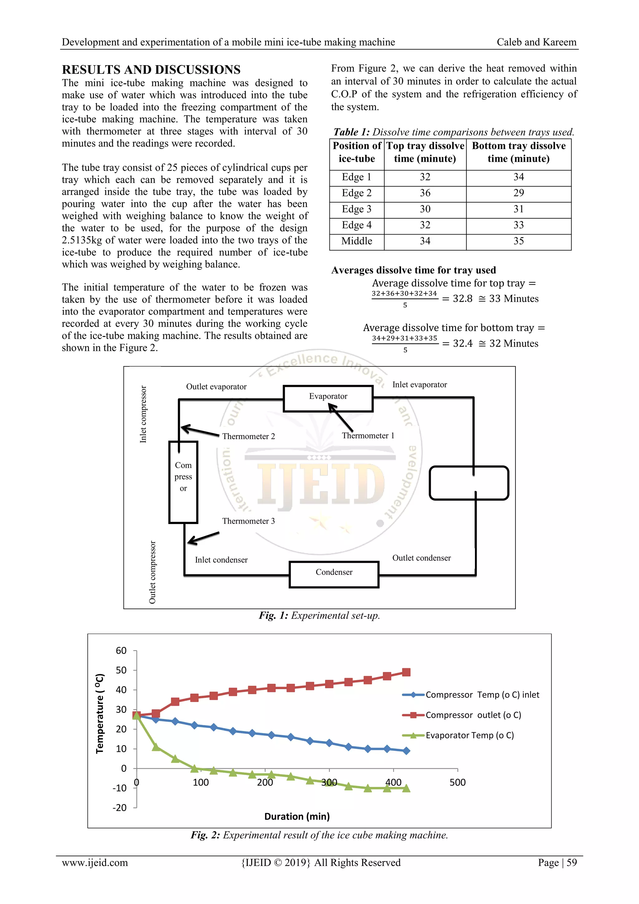
From Table 1 comparing the average dissolve time for
both trays, it is seen from the above calculation that the
top tray has the highest dissolve time of 33 minutes and
the bottom tray of 32 minutes, the difference in time of
dissolve is due to the time of unloading each tray from
the system since the time difference is some seconds
interval.
From Figure 2 at 90 minutes of continuous system
running, the water reached temperature of 0 0
C and after
90 minutes the temperature of the system reduced by 1
0
C interval for each minutes, this is as a reason that the
system is doing much work to transform the water to ice
at those temperatures. The temperature remains constant
at -3 0
C from 180 to 210 minutes; this might be as a
result that the ice formed is trying to harden changing
from ice slurries to ice-tube.
After 360 minutes of continuous operation of the system
it was noticed that the inside temperature of the system
did not change from -10 0
C, from this observation, it can
be said that the system has reach its constant enthalpy,
therefore the system can continue to run for various
hours with constant temperature of -10 0
C.
Coefficient of performance (C.O.P)
The coefficient of performance is the ratio of the cooling
load to the compressor power; the COP is mainly
affected by the change in evaporating and condensing
temperature.
Compressor power = 0.1647 hp
Ambient temperature = 27 0
C, Temperature after 30
minutes = 11 0
C
Heat removed per 30 minute (q) =
–
Heat removed per 30 minute (q) = 0.01867 kW
Actual C.O.P = (Rajput 2016) (9)
From (equation 18) Actual C.O.P =
COP theoretical =
COP theoretical = 7.108
Refrigerating efficiency =
Time taken to freeze 1kg of water = 2.15 hours
Time taken to produce ice-tube of 2.5135kg of water (50
ice-tubes) = 5.51 hours
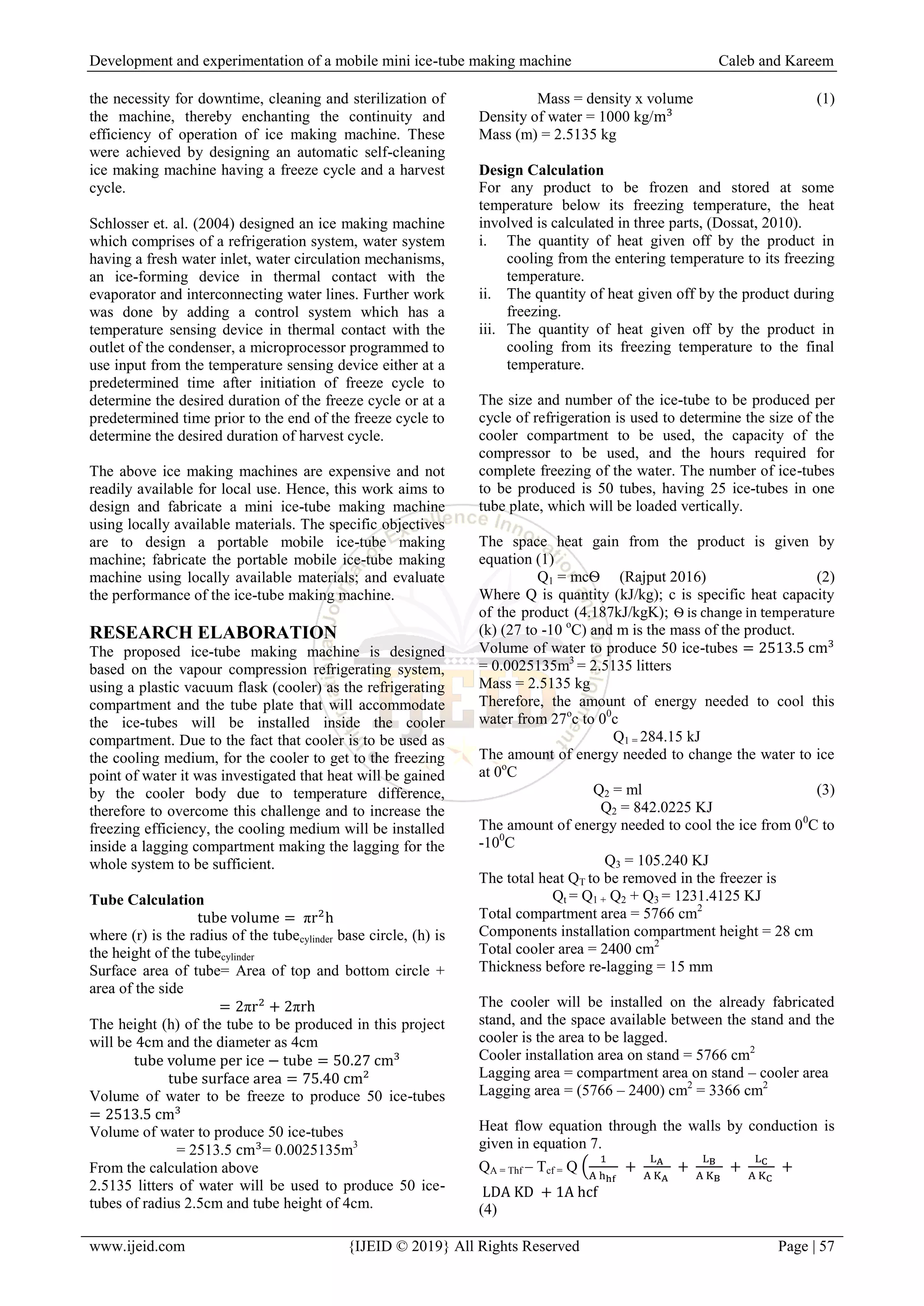
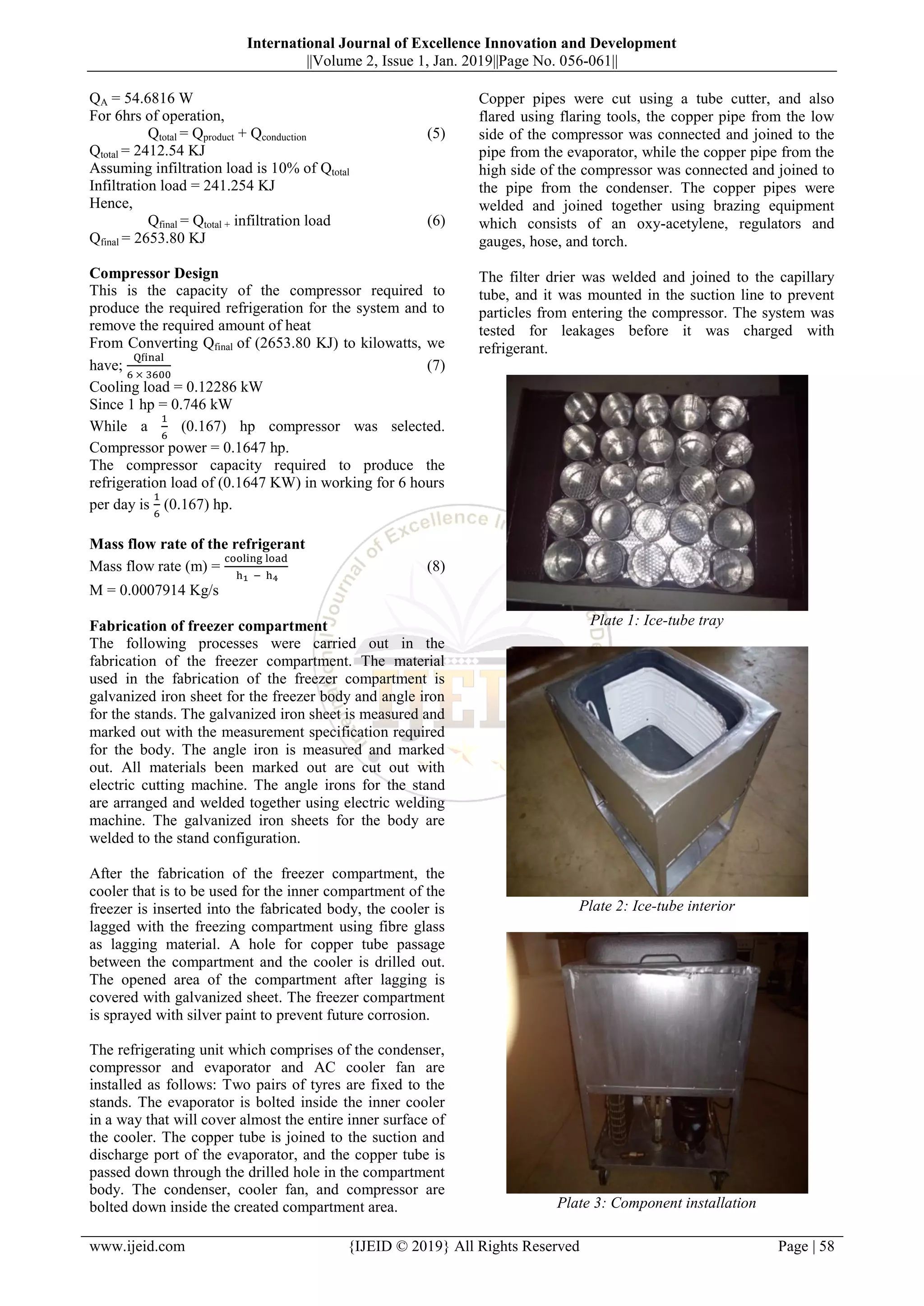
Plate 4: Ice-Tube Produced
CONCLUSION
A portable/mobile ice-tube making machine was
developed and evaluated. The machine ran for 5 hours
51 minutes to produce 50 pieces of ice-tube with 2.5135
kg of water using two ice-tube tray 25 pieces per tray,
and all part used for fabrication were selected to reduce
weight of the machine, reduce cost of production and
also increase the efficiency of the machine.
REFERENCES
[1] Abubakar, M., Andrew E. E., Akinola A. A.,
Abdulkadir B. H. (2012). Development and
Evaluation of a Prototype Refrigerated Cooling
Table for Conference Services. International
Journal of Engineering and Technology (IJET). 4
(2), 97 – 108.
[2] Ajeet, K. R. and Salem A. M. (2016). Study of
Performance Evaluation of Domestic Refrigerator
Working With Mixture of Propane, Butane and
Isobutene Refrigerant (Lpg). International Journal
of Mechanical Engineering and Technology
(IJMET). 7(3).
http://www.iaeme.com/IJMET/issues.asp?JType=I
JMET&VType=7&IType=
[3] Akinola, A. O.; Mogaji, T. S. and Adewole, K. A.
(2015). Development of a Solar-Powered Mobile
Refrigerator. International Journal of Emerging
Technology and Advanced Engineering
www.ijetae.com 5(9).
[4] ASHRAE, (2006). “Ice Manufacture,” ASHRAE
Handbook: Refrigeration. Inch-Pound Edition, pp.
34-41,
[5] Dickson, G and Westergaard, R.K (1984), Ice
Making Machine United States Patent 3791163
www.freepatentonline.com
[6] Dossat R.J, (2010) Principles of Refrigeration, 4th
edition Mohinder Singh Segwal for Wiley Eastern
Limited London, pp 206-213, 340-430
[7] Goldstein, V, (1991) Ice Making Machine
European Patent Application EP0316966.
www.freepatentonline.com
[8] Golob, P., Farrell, G. and Orchard, J. E. (2002).
Postharvest science and technology, principles and
practices. Blackwell Science. 554p.
[9] Kader, A. A. (2002a). Postharvest Technology of
Horticultural Crops. University of California,
Division of Agriculture and Natural Resources.
2nd Edition, Publication 3311, Berkeley, CA,
USA.
[10] Lemboye, K. T.; Layeni, A. T.; Oduntan, K.;
Akintunde, M. A. and Dahunsi, O. A. (2015).
Developing a Two Stage Cascade Compressor
Arrangement for Ice Block Production. Journal of
Machinery Manufacturing and Automation. 4 (2),
PP. 10-16.
[11] Meier, Gary B. (1992) Automatic ice block
machine, United States Patent
5167132.www.freepatentonline.com
[12] Rajput, R.K (2016) heat and mass transfer S.
Chand & Co. Ltd, New Delhi, pp150](https://image.slidesharecdn.com/ijeid201056061-190210091136/75/Development-and-Experimentation-of-a-Mobile-Mini-Ice-tube-Making-Machine-5-2048.jpg)
![Development and experimentation of a mobile mini ice-tube making machine Caleb and Kareem
www.ijeid.com {IJEID © 2019} All Rights Reserved Page | 61
[13] Sargent, S. A., Talbot, M. T. and Brecht, J. K.,
(1988). Evaluating Precooling Methods for
Vegetable Packinghouse Operations. Florida
Cooperative extension Service. Proc. Fla. State
Hort. Soc. Vol. 101, pp 175-182.
[14] Schlosser, C.E, Mueller, L.G and McDougal, G.
(1996). Ice making machine United States Patent
5586439. www.freepatentonline.com
[15] Schlosser, C.E, Pierskalla, C.J and Krcma, G.F
(2004) ice making machine and control method
therefor, European Patent EP0869321.
www.freepatentonline.com
Biography of Author(s)
CALEB, O. O. (B. Eng. Mechanical Engineering, M.
Eng. Building Services Engineering) is a lecturer at the
Department of Mechanical Engineering Federal
University of Technology Akure, Ondo State, Nigeria.
KAREEM, B. (B. Eng. Mechanical Engineering, M.
Eng. Production Engineering, PhD in Industrial
Engineering,) is Professor at the Department of
Industrial and Production Engineering Federal
University of Technology Akure, Ondo State, Nigeria.](https://image.slidesharecdn.com/ijeid201056061-190210091136/75/Development-and-Experimentation-of-a-Mobile-Mini-Ice-tube-Making-Machine-6-2048.jpg)
This document summarizes the design and experimentation of a mobile mini ice-tube making machine. Key points: - The machine was designed to produce 50 ice tubes using 2.5135 kg of water in 5 hours and 51 minutes. It uses a food flask as the cooling compartment within an insulated metal frame. - Design calculations were performed to determine the required volume of water, heat removal needs, insulation requirements, and compressor capacity. - The machine was fabricated using locally available materials like metal sheets and angle iron. Refrigeration components were installed and the system was tested. - Experimental results showed the temperature reduction over time and the average dissolve times for ice tubes in different tray positions. The