Downloaded 98 times
![Review
[1] W. H. C. Gordon R. Johnson, "A constitutive model and data for metals
Subjected to large strains, high strain rates and high temperatures.," Proc. 7th Int.
Symposium on Ballistics, Hague, Netherlands, April 1983, pp 541-548.
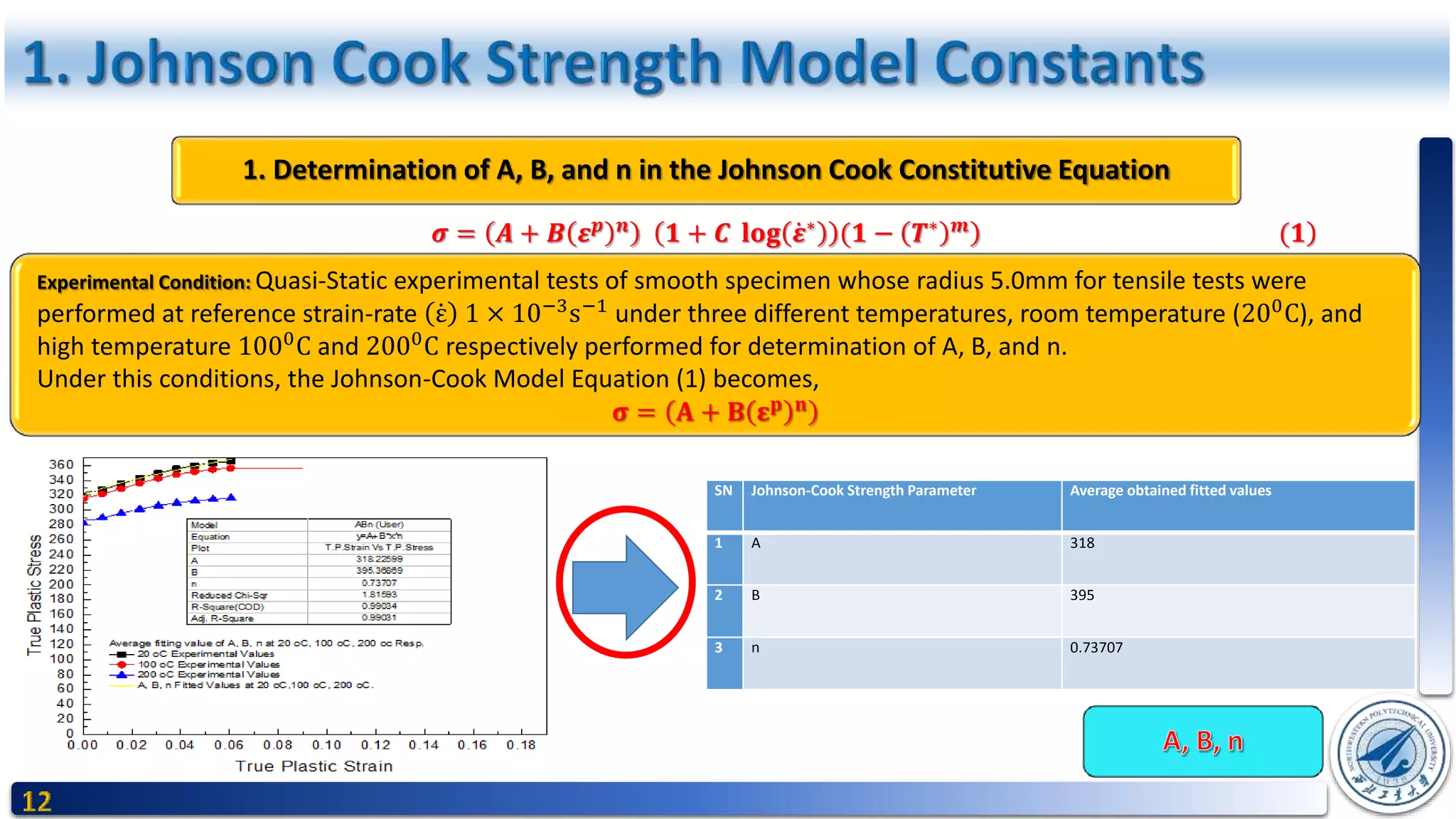
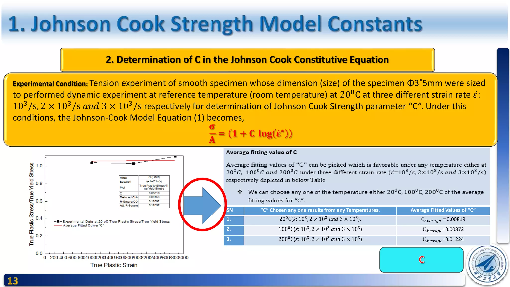
William H. Cook and Gordon R. Johnson, presents a constitutive model and data for materials subjected to large
high strain rates and high temperatures. The model for the von Mises flow stress, σ, is expressed as
𝝈 = 𝑨 + 𝑩 𝜺 𝒑 𝒏
𝟏 + 𝑪 𝐥𝐨𝐠 𝜺∗
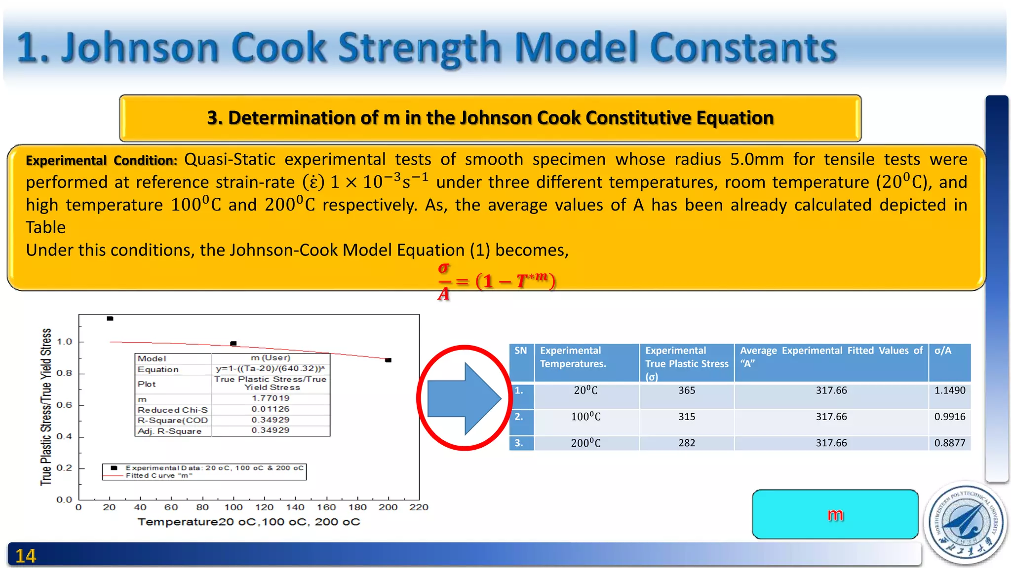
(𝟏 − (𝑻∗
) 𝒎
) (1)
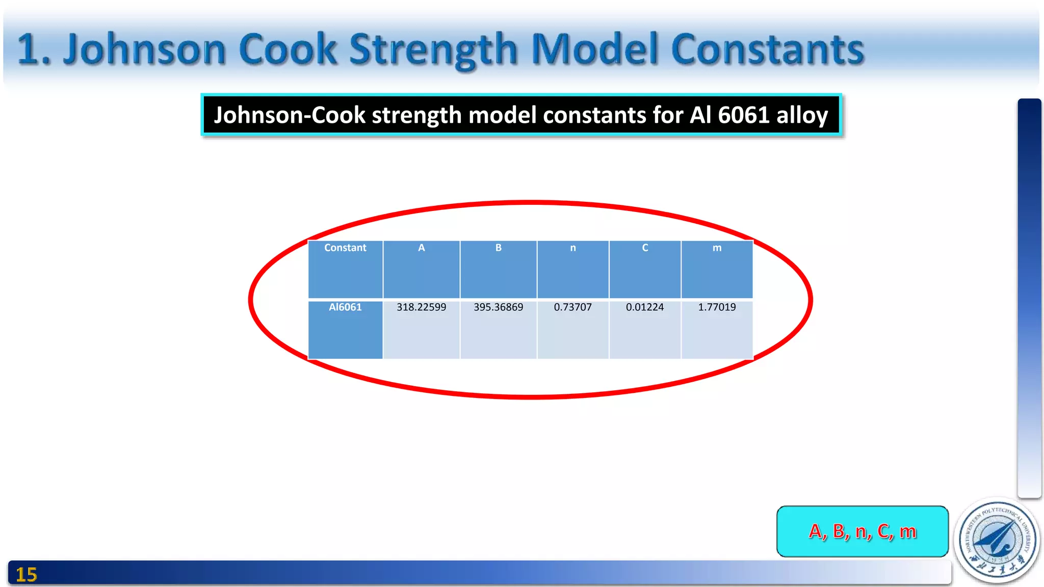
Where A, B, C, n and m are material constants, and are determined from an empirical fit of flow stress (as a function of
strain, strain rate and temperature) to Equation (1).
Where, ɛ 𝒑
= the equivalent plastic strain, ε∗
= ε 𝜀0is the dimensionless plastic strain rate for 𝜀0 = 1 s−1
(reference strain-
rate).
And T∗m
= ((Ttest − Troom) (Tmelt − Troom))m
is non-dimensional homologous temperature, where T is the absolute
temperature, Troom is the room temperature, and Tmelt is the material melting temperature.
The first bracket in Equation (1) gives the isothermal stress as a function of strain for 𝜀0 = 1s−1
(reference strain-rate for
convenience). The second bracket includes the strain rate effect and third bracket accounts for the thermal effects.](https://image.slidesharecdn.com/presentation-170918202321/75/Determination-of-Johnson-Cook-Material-s-Strength-Parameter-Fracture-Parameter-And-Application-to-Bullet-Impact-Resistance-of-Al-6061-alloy-3-2048.jpg)
![Review
The basic form of the fracture model developed was first presented in Ref. [2] The damage to an element is
defined
𝑫 = 𝜮
𝜟𝜺
𝜺 𝒇 (2)
where 𝜟𝜺 is the increment of equivalent plastic strain which occurs during an integration cycle, and 𝜺 𝒇
is the equivalent
strain to fracture, under the current conditions of strain rate, temperature, pressure and equivalent stress. Fracture is
then allowed to occur when D = 1.0. The general expression for the strain at fracture is given by
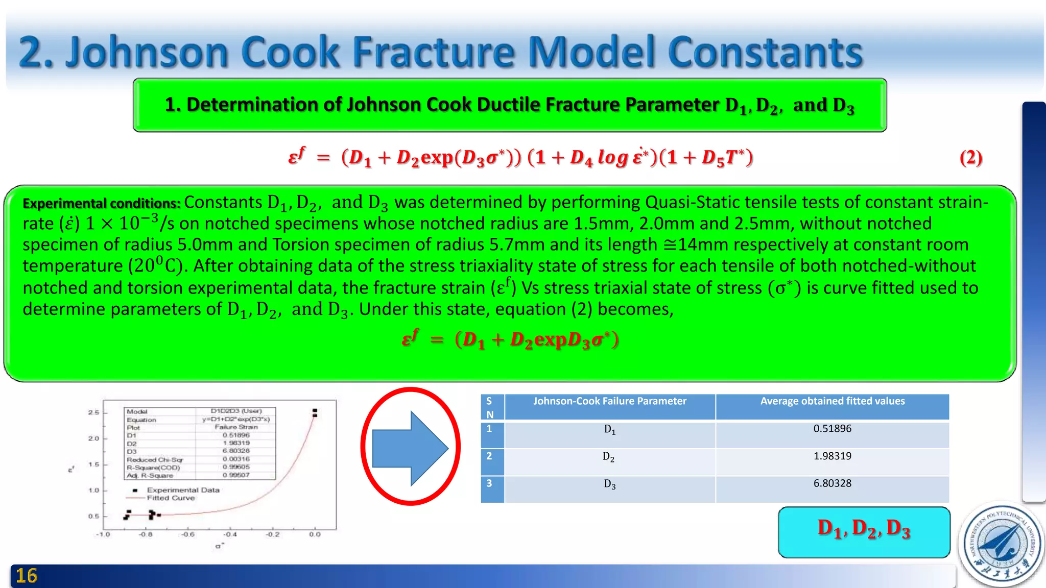
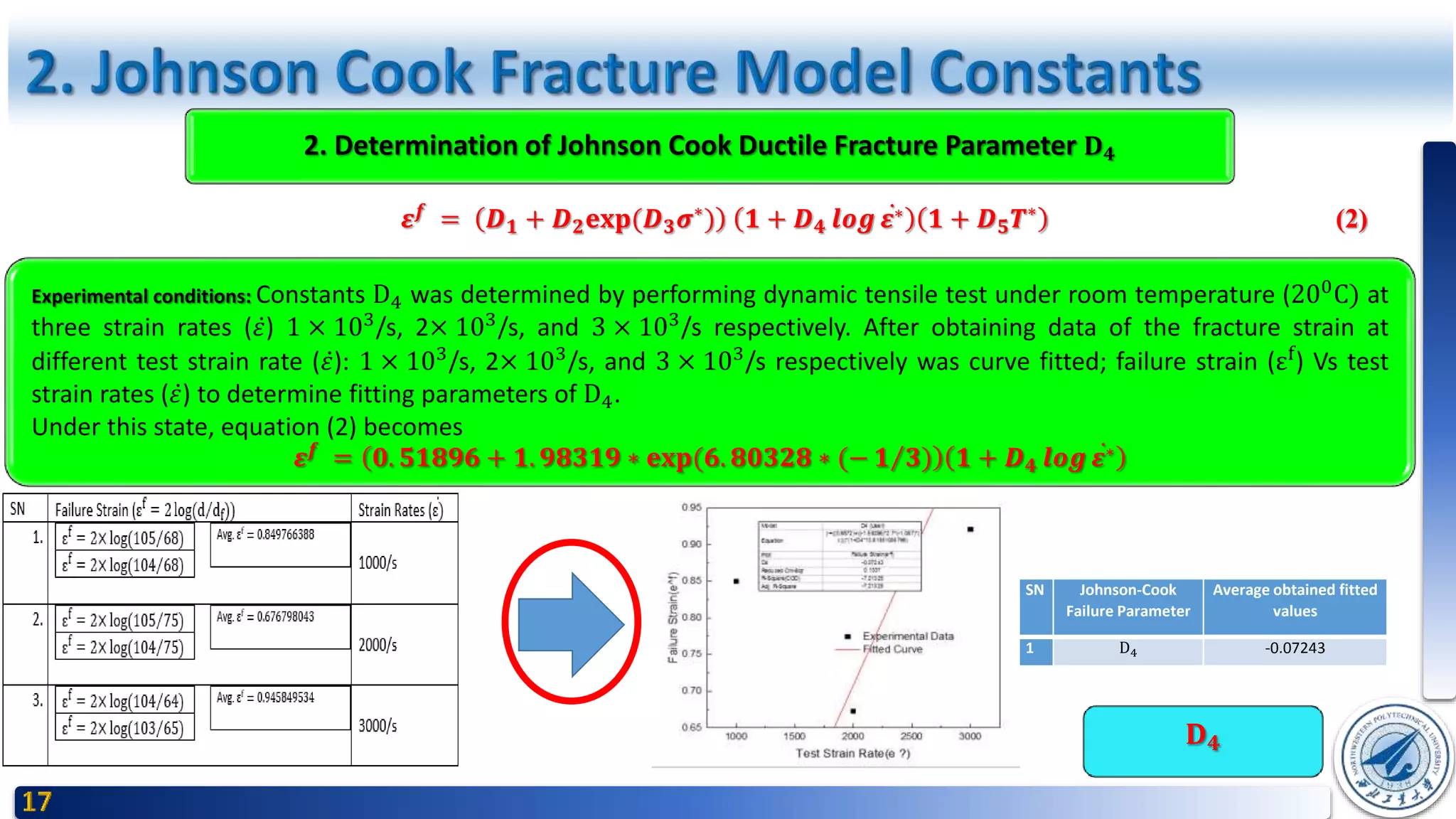
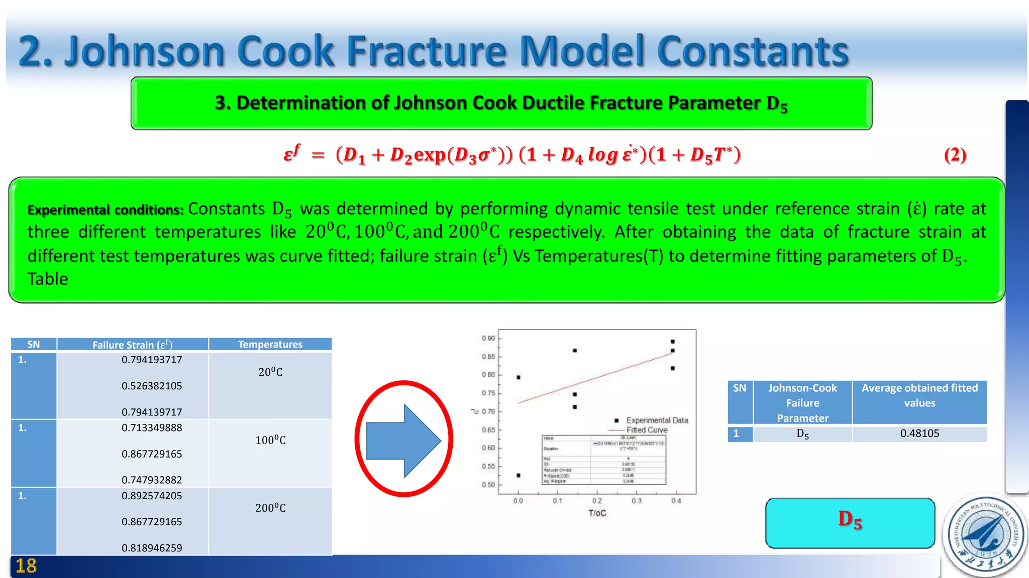
𝜺 𝒇
= 𝑫 𝟏 + 𝑫 𝟐 𝒆𝒙𝒑𝑫 𝟑 𝝈∗
𝟏 + 𝑫 𝟒 𝒍𝒐𝒈 𝜺∗ 𝟏 + 𝑫 𝟓 𝑻∗
(3)
for constant values of the variables (σ∗
, ε∗, T∗
) and for σ∗
≤ 1.5. The dimensionless pressure-stress ratio is defined as σ∗
=
σ 𝑚 σ where σ 𝑚 is the average of the three normal stresses and σ is the Von Mises equivalent stress. The dimensional
strain rate, ε∗, and homologous temperature, T∗
, are identical to those used in the strength model of equation (1).
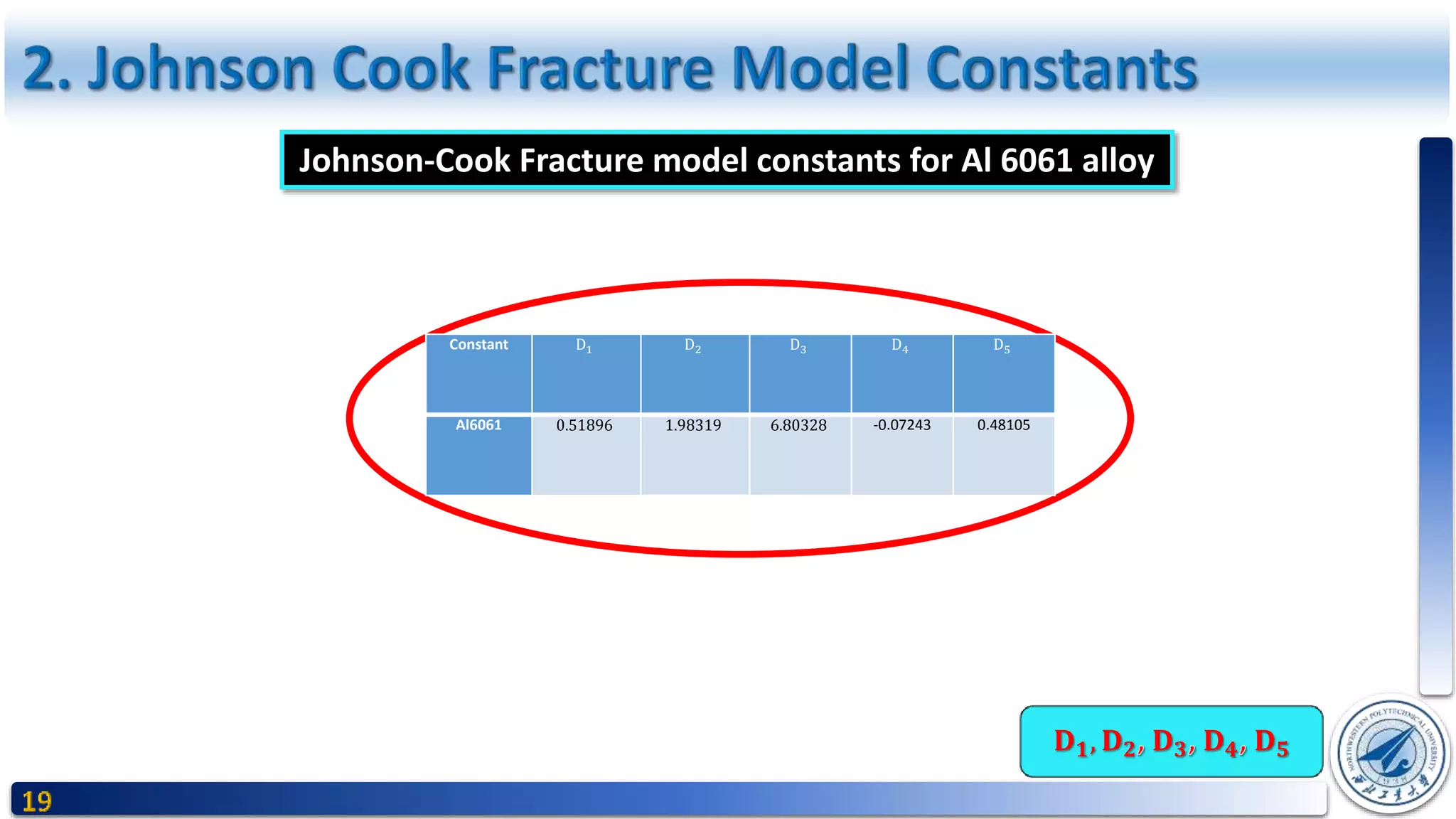
The parameter 𝑫 𝟏, 𝑫 𝟐, 𝑫 𝟑, 𝑫 𝟒&𝑫 𝟓 are constants.
[2] G. R. Johnson, "Material Characterization for Computations Involving Severe Dynamic
Loading.," Proc. Army Symp. on Solid Mechanics, 1980, Work in Progress, Cape Cod, Mass., vol.
pp. 62-67., (Sept. 1980).](https://image.slidesharecdn.com/presentation-170918202321/75/Determination-of-Johnson-Cook-Material-s-Strength-Parameter-Fracture-Parameter-And-Application-to-Bullet-Impact-Resistance-of-Al-6061-alloy-4-2048.jpg)
![Review
The five constants are 𝑫 𝟏 … . 𝑫 𝟓 , The expression in the first set of brackets follows the form presented by Hancock and
Mackenzie [3]. It essentially says that the strain of fracture decreases as the hydrostatic tension, σ 𝑚, increases. The
expression in the second set of brackets represents the effect of strain rate, and that in the third set of brackets represents
the effect of temperature.
Plastic Flow And The Stress-State
Since, this fracture model is based on fracture strains at constant σ∗
, 𝜀∗
, and T∗
, and it is accurate under constant
conditions to the extent that the equivalent stress, σ, equivalent strain, 𝜺, and equivalent strain rate, 𝜀∗
, can represent the
more complicated stress and strain relationships [4].
σ =
1
2
[ σ1 − σ2
2 + σ2 − σ3
2 + (σ3−σ1)2] (4)
ε =
2
9
[ ε1 − ε2
2 + ε2 − ε3
2 + ε3 − ε1
2] (5)
𝜀 = ∑ 𝜀∆𝑡 6
Both Equivalent effective plastic strain and Equivalent effective stress are unaffected by a third important , the mean stress
σ 𝑚 =
1
3
(𝜎1 + 𝜎2 + 𝜎3) (7)
Which may, however, be combined with σ in to a single non-dimensional parameter σ 𝑚 σ which characterizes a stress-
state and of its “TRI-AXIALITY”.
[3] J. W. H. a. A. C. Mackenzie, "On the mechanisms of ductile failure in high-strength steels subjected to multi-axial stress-states.," Journal of the Mechanics
and Physics of Solids, 24, 147-169., (1976).
[4] W. H. C. Gordon R. Johnson, "Fracture Characteristics of the three metals subjected to various strains, Strain
rates, Temperatures and Pressures.," Engineering Fracture Mechanics Vol. 21, No. 1, pp.31-48, (1985).](https://image.slidesharecdn.com/presentation-170918202321/75/Determination-of-Johnson-Cook-Material-s-Strength-Parameter-Fracture-Parameter-And-Application-to-Bullet-Impact-Resistance-of-Al-6061-alloy-5-2048.jpg)
![Review
1- Radial
2- Hoop
3- Axial
[6] Chen Zhong Fu. CHEN Gang*, XU Wei-Fang, CH EN Yong-Mei, HUANG Xi-Cheng, "45钢的J-C损伤失效参量研
究陈刚," China Academic Journal Electronic Publishing House, vol. 27, No.2, (March 2007).
[5] P. W. Bridgman, "Studies in Large Plastic Flow and Fracture.," McGraw-Hill, New York, (1952).
(A discussion of the applicability of BRIDGMAN’S (1952) analysis to pre-notched specimens has been given by EARL and BROWN (1976)[5]). The main feature
of their analysis state that equivalent effective plastic strain remain constant across the mean cross-section, but the RADIAL, HOOP and AXIAL stresses (σr,
σθ, and σz, resp.) vary across the section as shown in Fig. 1. The value of σ 𝑚 σ = 𝜎∗
rises from 1/3 at the surface to a maximum value on the axis of the
specimen, and (σ 𝑚 σ) = -(𝜎∗
) =
1
3
+ log(1 +
𝑎
2𝑅
) at the axial line behind in the main equation of ”Johnson Cook Fracture Model Equation”[6].
Where, R is the profile radius of the circumferential notch and d is the radius of the minimum cross-section.
Thus, the stress-state is defined by the geometry of the specimen, and effective plastic strain is 𝜀 𝑝
= 2 log( 𝑑0 𝑑).
Where, 𝑑0 is the initial value of d.](https://image.slidesharecdn.com/presentation-170918202321/75/Determination-of-Johnson-Cook-Material-s-Strength-Parameter-Fracture-Parameter-And-Application-to-Bullet-Impact-Resistance-of-Al-6061-alloy-6-2048.jpg)
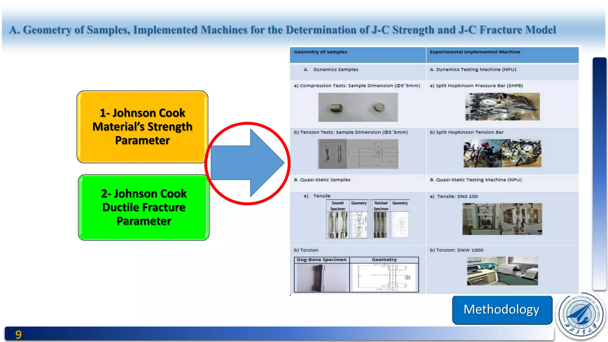
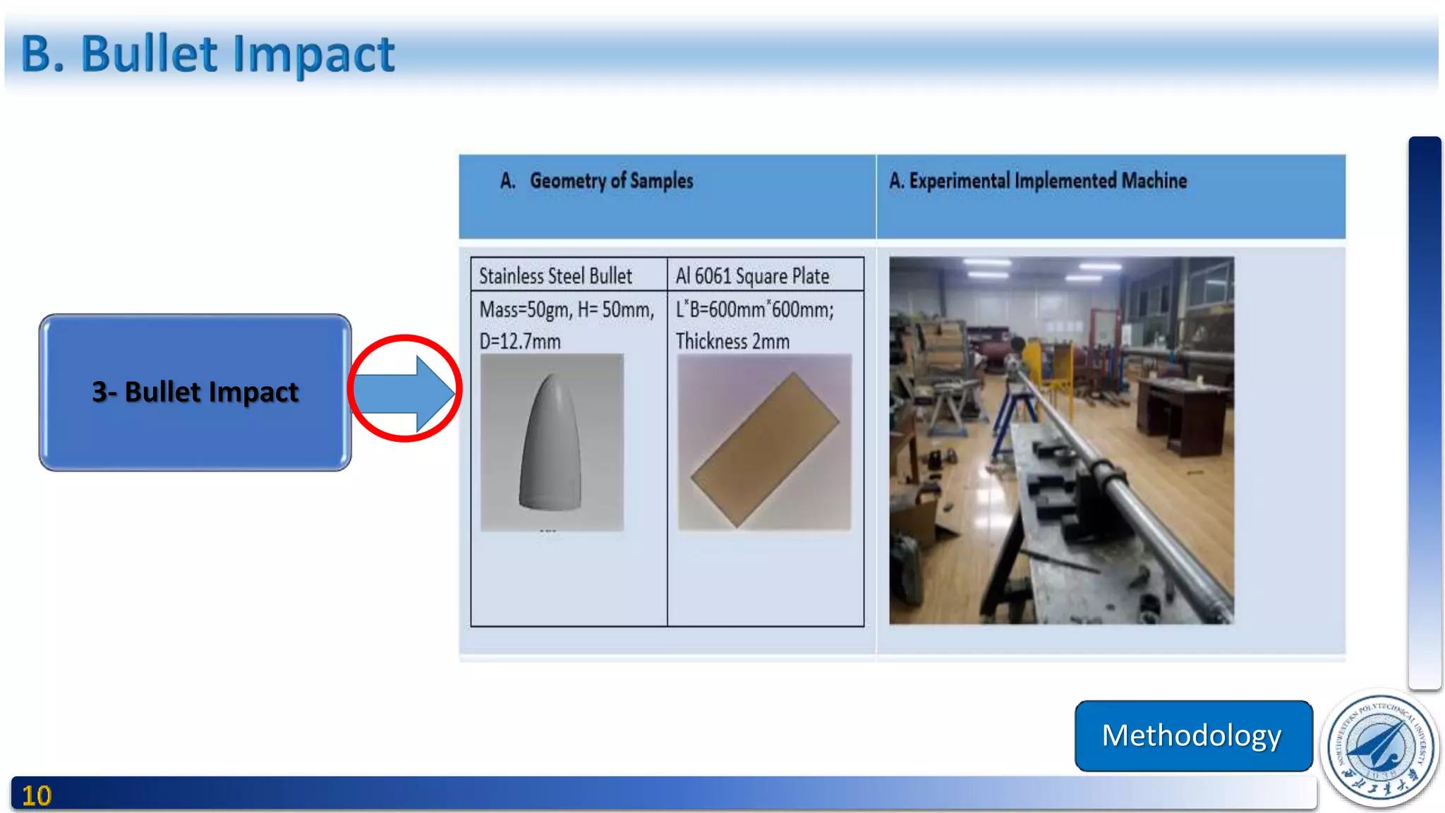


This document presents a study on determining the Johnson-Cook material strength and fracture parameters and their application to assess the bullet impact resistance of the AL 6061 alloy. It includes a literature review, methodology for experimentation, and analysis of results involving quasi-static and dynamic tensile tests across various temperatures and strain rates. The study aims to fit equations for material behavior under extreme conditions, providing constants necessary for the Johnson-Cook model to predict performance under bullet impact.


