Download as PDF, PPTX
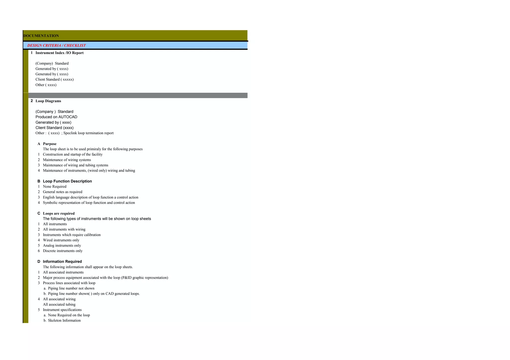


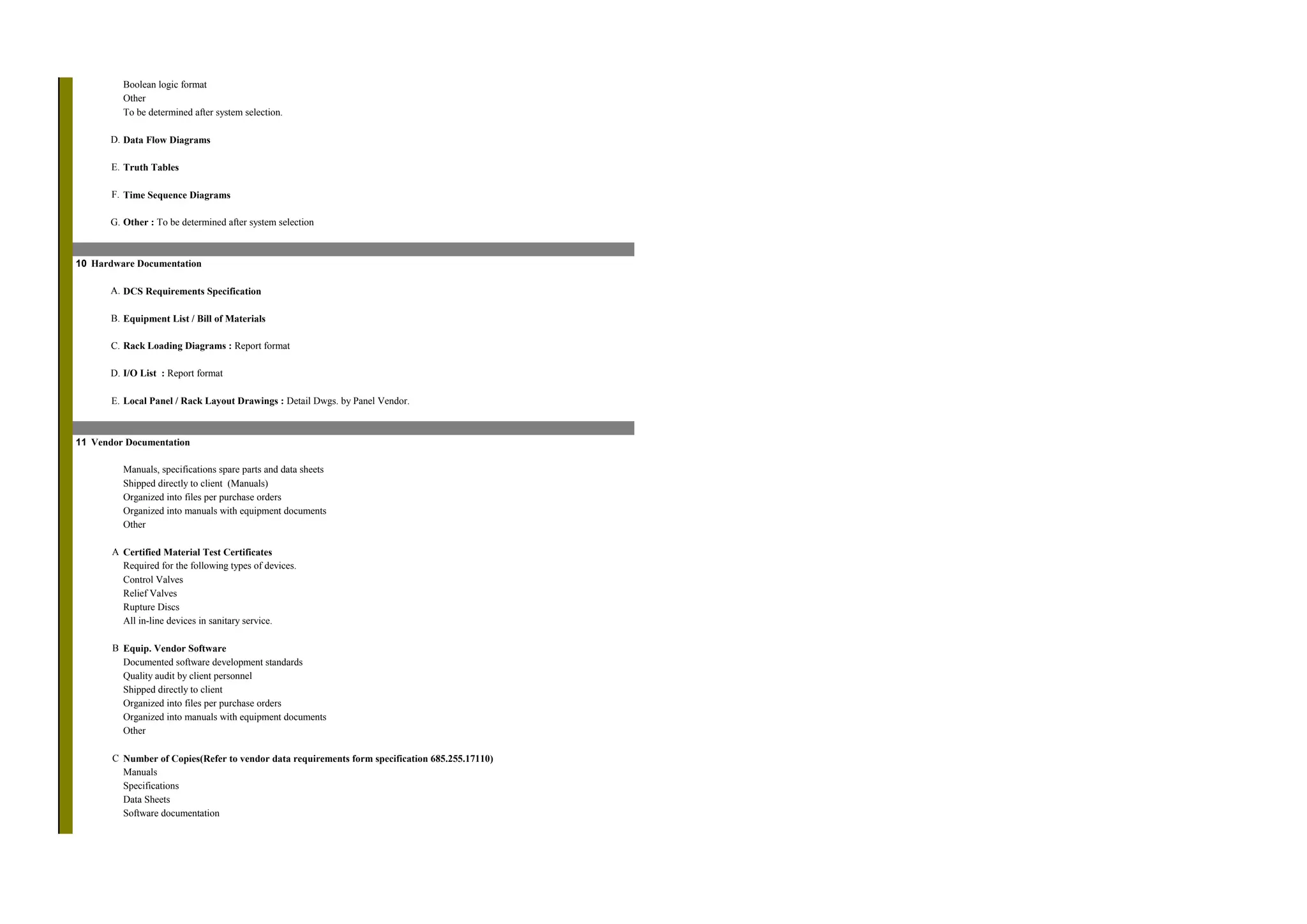

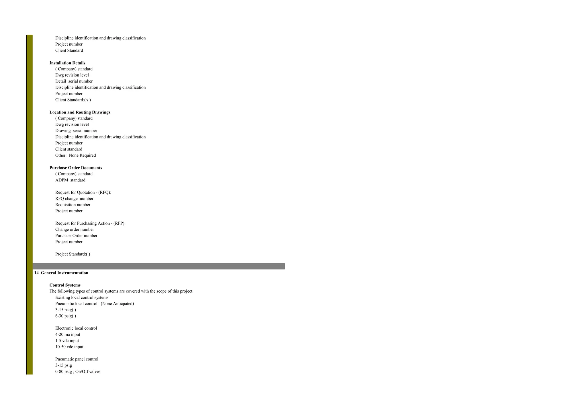


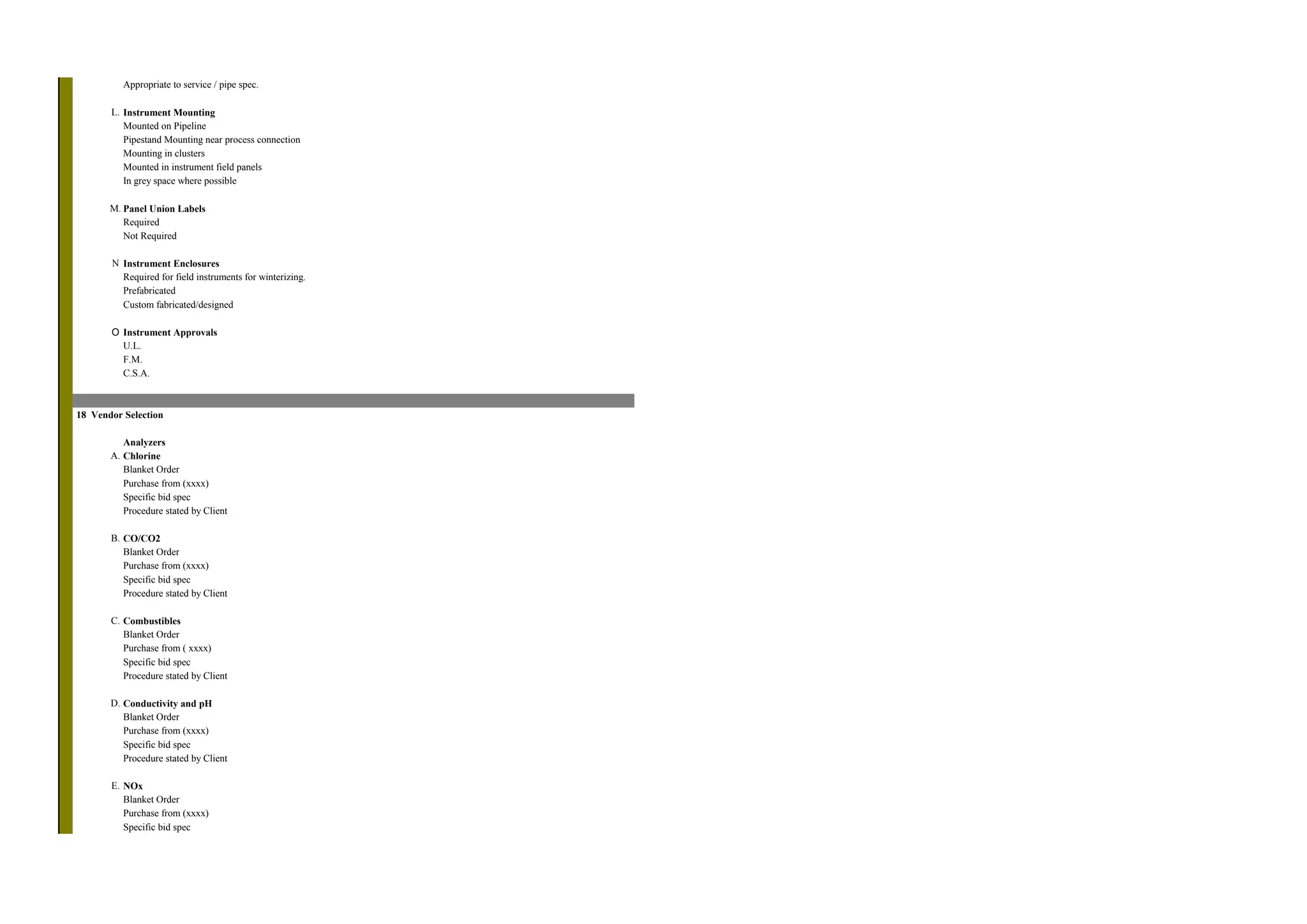


This document provides design criteria and a checklist for instrumentation documentation. It outlines requirements for various documentation deliverables including instrument indexes, loop diagrams, specifications, calculations, installation details, location drawings, purchase documents, software and hardware documentation, and vendor documentation. It also provides guidance on general instrumentation including required control systems, signal levels and indications, tagging, and electrical classifications. The overall purpose is to ensure consistent and complete documentation is developed to support construction, startup, and long-term maintenance of the facility's instrumentation and control systems.


