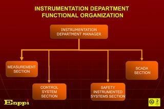
The document describes the organization and functions of an instrumentation engineering division within an electrical and instrumentation engineering department. It includes organizational charts of the division and department, descriptions of the roles and responsibilities of different sections and managers, and an overview of the deliverables, software, standards, and interfaces of the instrumentation engineering work.


![DELIVERABLES
Instrument Index.
Instrument Tagged Items Data Sheets
[ Detailed Specifications].
Control & Safety Systems Basic Design
Package:
Technical Specifications.
Architectural/conceptual Diagrams.
Input/Output Data Base Schedules.
Functional loop Diagrams.
Logic/Ladder Diagrams.
Control Rooms Equipment Conceptual
Layout Drawings.
Dynamic Graphics/Display Sketches.](https://image.slidesharecdn.com/icsorintation-230410052945-a4f4b70b/85/I-CS-orintation-pptx-9-320.jpg)
![DELIVERABLES [Continued]
Instrument Bulk Material Data Sheets &
Specifications, e.g.: Instrument Cables Data
Sheets, Junction Boxes Specifications,
Elec./ Mechanical/ Pneumatic Bulk Material
Specifications.
Plant Overall Instrument Cables Block
Diagrams.
Control Building Equipment Layout & Cable
Routing Details.](https://image.slidesharecdn.com/icsorintation-230410052945-a4f4b70b/85/I-CS-orintation-pptx-10-320.jpg)
![DELIVERABLES [Continued]
Field Instruments Hook-Ups [Elec./
Mechanical/ Pneumatic/ Supports].
Field Instruments Layouts (Elec./
Pneumatic).
Field Instrument Cable Routing With Tray/
Trench Sections & Road Crossing Details.
Cables/ Tubing Schedules.](https://image.slidesharecdn.com/icsorintation-230410052945-a4f4b70b/85/I-CS-orintation-pptx-11-320.jpg)
![DELIVERABLES [Continued]
Interconnecting Wiring Diagrams.
Instrument Loop Diagrams.
Calculations For Instruments Sizing; e.g.:
Flow Meters Sizing & Control Valves
Sizing.
MRQ’s For Control & Safety Systems,
Tagged Items.](https://image.slidesharecdn.com/icsorintation-230410052945-a4f4b70b/85/I-CS-orintation-pptx-12-320.jpg)
![DELIVERABLES [Continued]
Technical Bid Evaluation Reports.
MRP’S For Control & Systems, Tagged
Items.](https://image.slidesharecdn.com/icsorintation-230410052945-a4f4b70b/85/I-CS-orintation-pptx-13-320.jpg)
![SOFTWARE PACKAGES USED IN DESIGN ACTIVITIES
MMS [Material Management System].
AUTOSIM.
Boiler Simulation.](https://image.slidesharecdn.com/icsorintation-230410052945-a4f4b70b/85/I-CS-orintation-pptx-14-320.jpg)
![SOFTWARE PACKAGES USED IN DESIGN ACTIVITIES
[Continued]
Intools Package. [Full Range Application
Modules + Infomaker Module]
Intergraph 2D/ 3D Plant Design.
Auto CAD.](https://image.slidesharecdn.com/icsorintation-230410052945-a4f4b70b/85/I-CS-orintation-pptx-15-320.jpg)


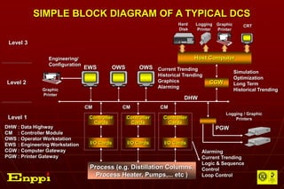
![The Three Basic Types Of Computer Based Control
Systems Available In The Market Are :
The supervisory Digital Control System [SDC].
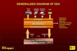
The Direct Digital Control System [DDC].
The Distributed Control System [DCS].
The DCS Is the Most Recent type Of Computer
Based Control Systems.](https://image.slidesharecdn.com/icsorintation-230410052945-a4f4b70b/85/I-CS-orintation-pptx-21-320.jpg)


![BASIC INDUSTRIAL AUTOMATION NEEDS [continued]
Reduced Operation Cost.
Better Performance.
Powerful, User Friendly Control Room
Operations.
Alarm/Event Analysis.](https://image.slidesharecdn.com/icsorintation-230410052945-a4f4b70b/85/I-CS-orintation-pptx-26-320.jpg)
![BASIC INDUSTRIAL AUTOMATION NEEDS [continued]
Easy To Implement Advanced Control
Strategies.
Capability of Continuously Coping With
Evolving Industrial Automation
Technologies & Standards.](https://image.slidesharecdn.com/icsorintation-230410052945-a4f4b70b/85/I-CS-orintation-pptx-27-320.jpg)