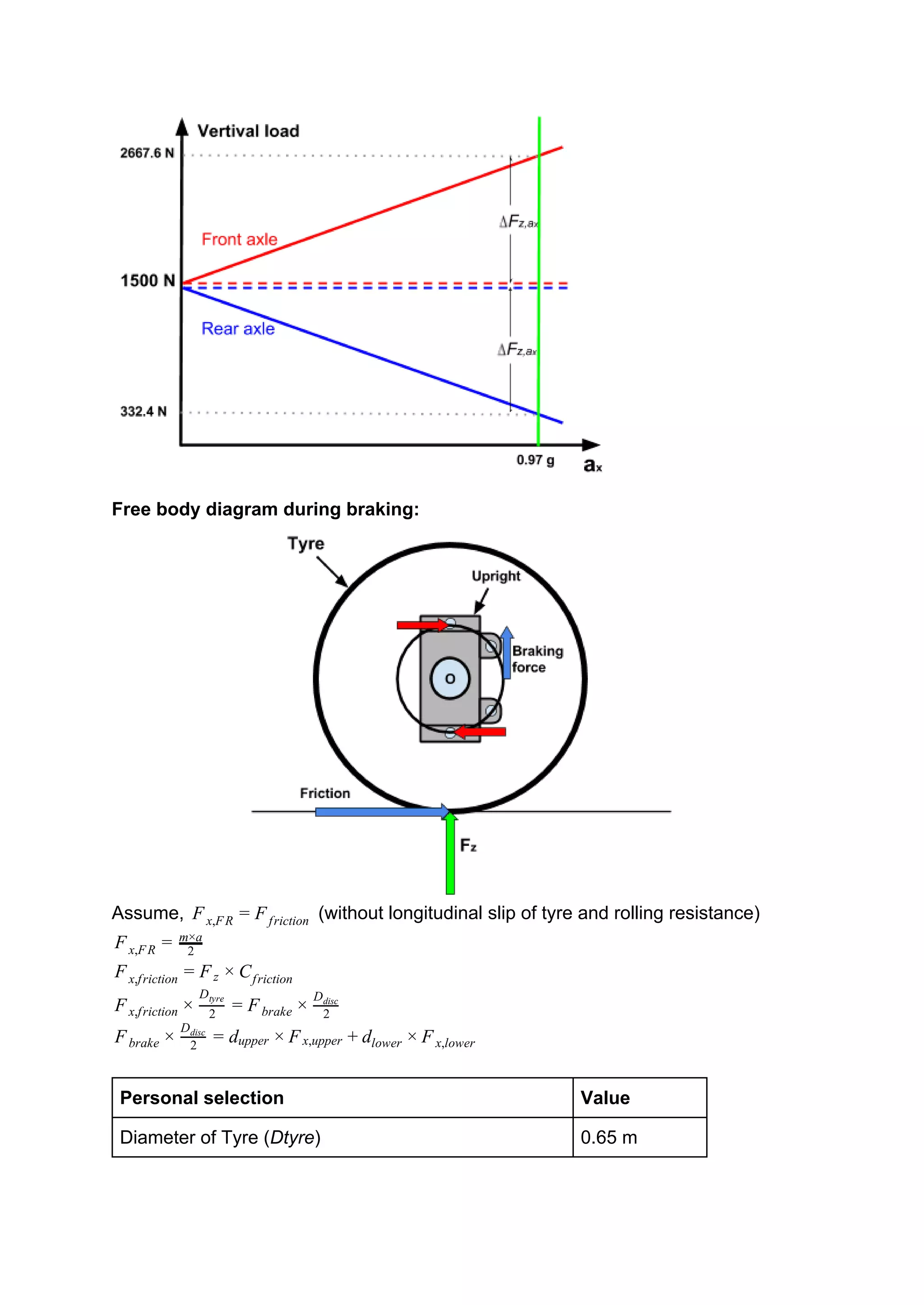
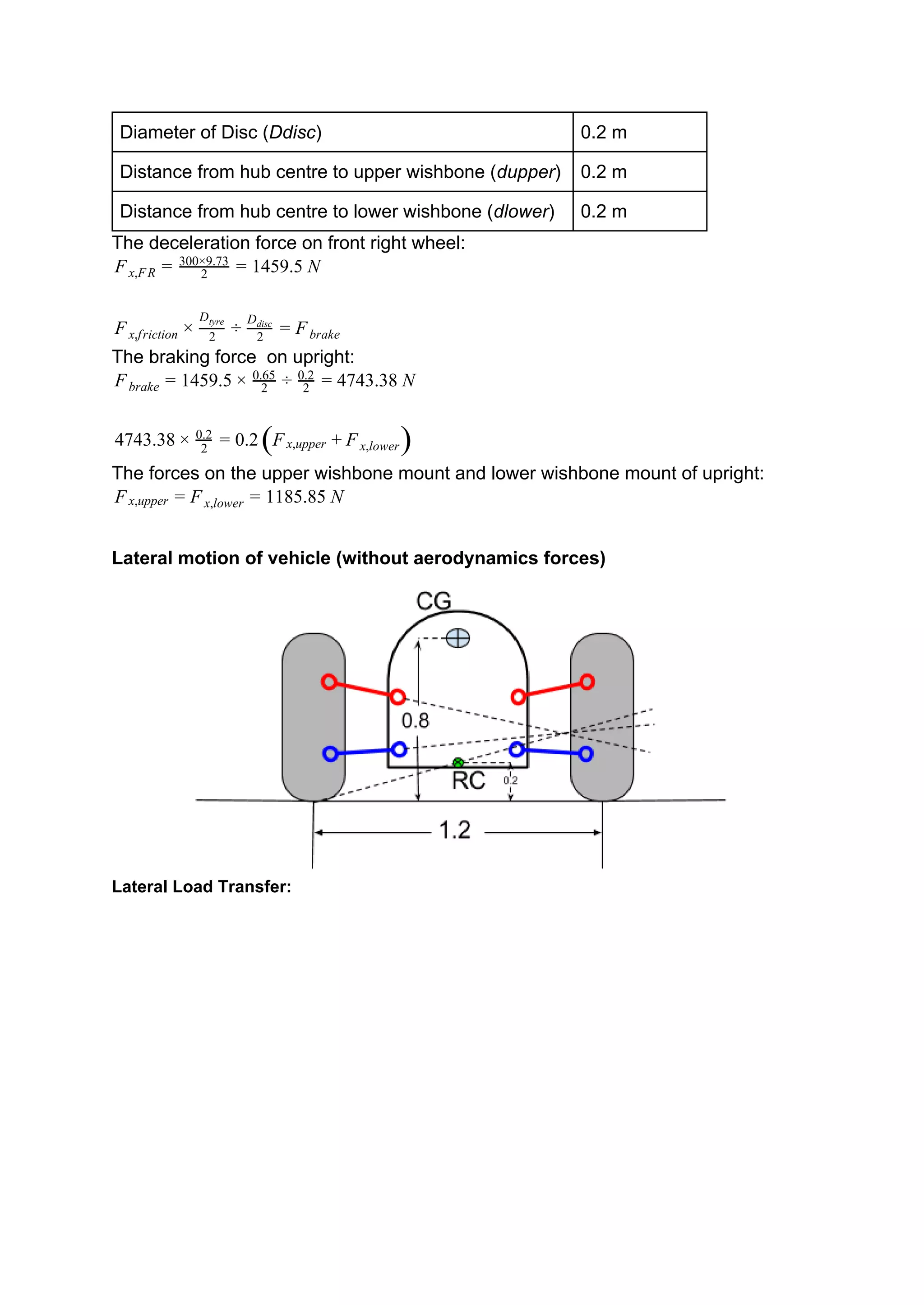
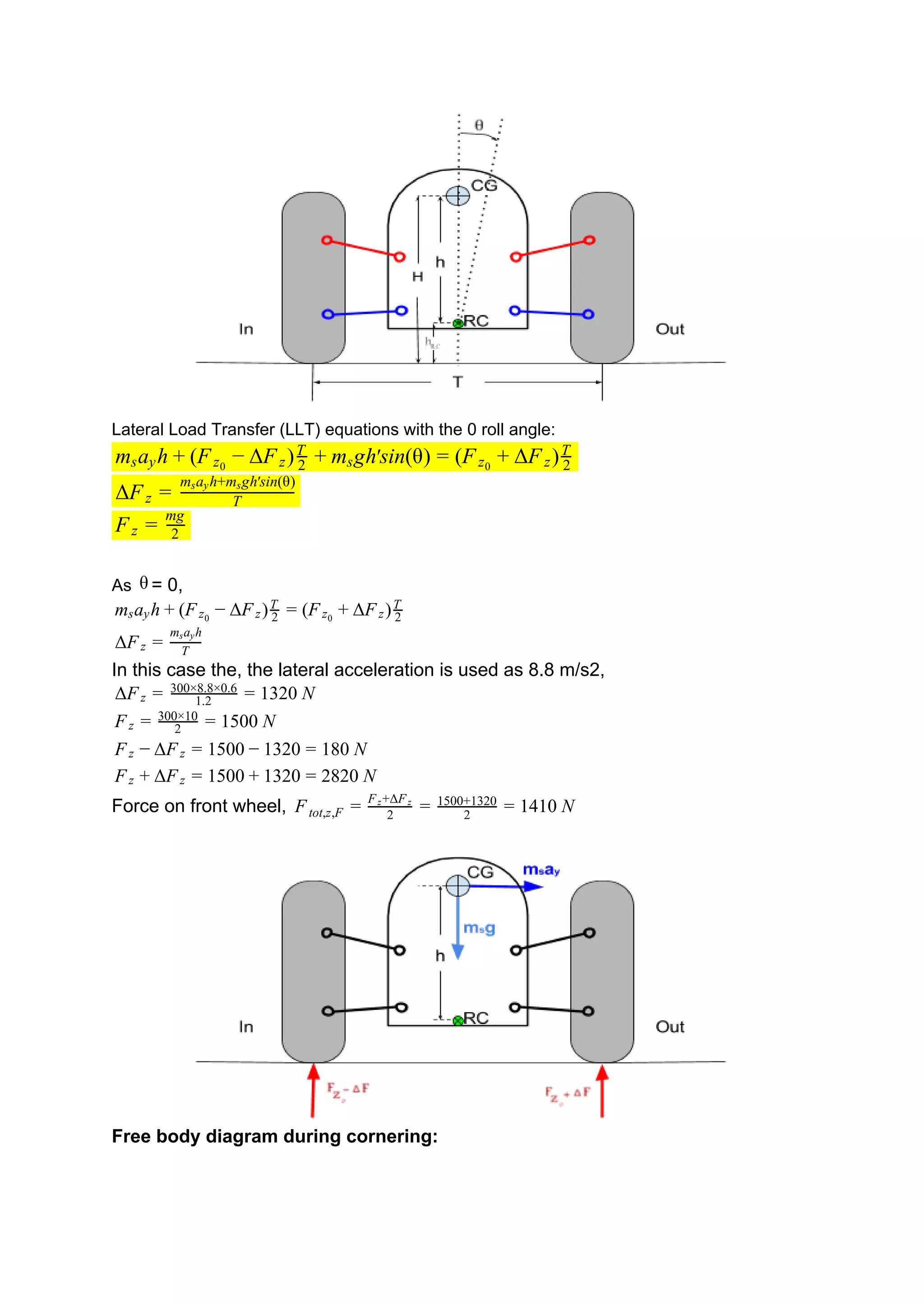
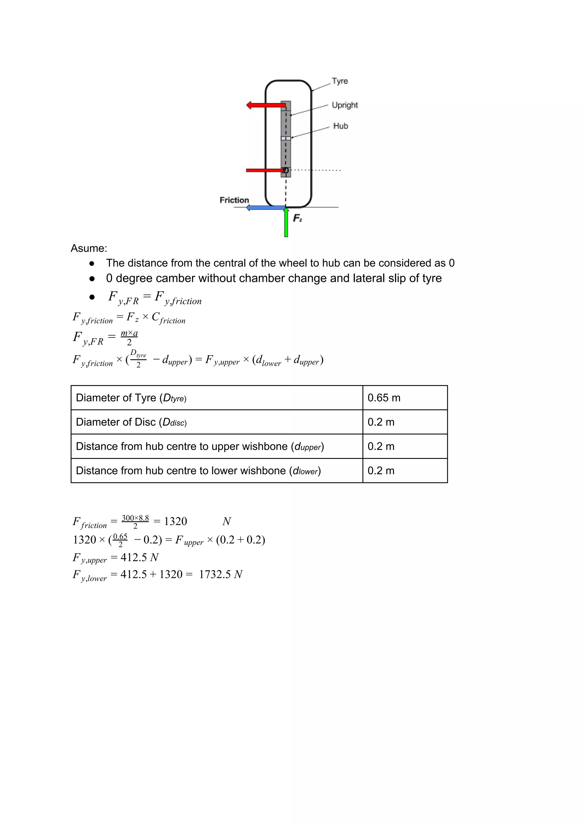
Faculty of Science, Engineering and Computing
School of Mechanical and Aerospace Engineering
Assignment:
Design and optimization of parts of a
suspension system
Module:
ME7733 Automotive Aerodynamics and Structural Analysis
Setter: Dr D Venetsanos
Deadline: 28 April 2017
Name: SHIH CHENG TUNG
KU number: K1617281
Course: Msc Automotive Engineering
Contents
A.​ ​Theoretical questions
B. Preliminary calculations
C. Design of two parts for a front suspension system
D. Finite Element Analysis of two parts for a front suspension
system
E. Structural optimization of two parts for a front suspension
system
F. Quality of Report - Conclusions
A. Theoretical questions
1. What is ‘Finite Element Analysis (FEA) of a structure’?
The Finite Element Analysis could be referred to as finite element method (FEM) that
conducts a numerical method to deal with of engineering and mathematical
problems.
2. In FEA, what is ‘pre-processing’ and what is ‘post-processing’ of a model?
Pre-processing aims to develop a suitable finite element mesh, allocate reasonable
material properties and adopt boundary conditions in the form of restraints and
loads. After the finite element model has been solved, post-processing could be
applied. In terms of post-processing, the desirable results of analysis is performed to
investigate the characteristics and visualise the model by graphical techniques.
3. In FEA, what is a ‘Degree of Freedom’?
The Degree of freedom (DOF) is based on the concept of number of forces which
are transmitted and consequently the loads and restraints. The translational DOF
includes moving up/down, left/right and forward/backward, also indicates the forces
transmitted. The rotational DOF includes yawing, pitching and rolling, which indicates
moments transmitted.
4. How many degrees of freedom does a beam element have and which are
these?
In 3D: 6 (translation in X, Y, Z; rotation in X, Y, Z)
In 2D: 3 (​translation in X, Y; rotation in Z)
5. How many degrees of freedom does a plate element have and which are
these?
5 (translation in X, Y, Z; Two in-plane rotation DOFs)
The out-of-plane rotational DOF is not considered for plate elements.
6. How many degrees of freedom does a node of a 3D solid element have and
which are these?
3 (translation in X, Y, Z)
7. Describe all possible supports at the end of a 3D beam and provide a
sketch.
There are 5 main types of supports:
Type and sketch Supports
rotation, horizontal and vertical
horizontal and vertical
vertical
vertical and horizontal.
vertical
8. What is optimization?
The optimization could be defined as ‘a problem in certain parameters (design
variables) which needed to be determined to achieve the best measurable
performance (objective function) under given constraints.’ There are number of
design objectives, for example, to minimise the weight of design under reasonable
stress and to minimise the maximum stress in the structure.
9. What is a deterministic and what is a stochastic optimization procedure?
The deterministics optimization (DO) method is a faster solution for convergence,
which requires lower number of variables of evaluation. The results of DO method
are unequivocable and replicable.
The stochastics optimization (SO) procedure conducts and utilises random variables
for formulation of stochastics problems including random constraints or objective
functions as well as random iterates. For deterministic problem, SO method
recapitulate ​deterministic method as well.
10. What does the term “objective function” describe in optimization?
The objective function would be a numerical value which is minimise or maximise in
the optimization. To express a desirable goal in form of mathematics, an equation is
optimized with given certain constraints and variables by programming techniques.
In other words, the objective function indicates the proportion between variable
contribution and the value of optimization. The function could be the form as follows:
(x) f (x), f (x), f (x), .., f (x)}F = { 1 2 3 . p
11. What do the term “design variable” and “design vector” describe in
optimization?
The design variables are the parameters which control the geometry of the optimized
structure by continuous or discrete variables. The design vector
, expresses the range of potential changes.x , , x , .., x }x = { 1 x2 3 . n
12. What is an “initial design vector” in optimization?
An initial design vector provides the estimation of performance characteristics to the
physical model. It could generate the outputs which are used to approximate cost,
price, and baseline demand figures for the design.
13. What does the term “constraint” describe in optimization?
The constraint means the limitation of the design variables, which is divided into two
forms. The common one in the optimization is an inequality constraint:
, are the calculated and limited
values of constraints and is the number of the inequality constraints functions. InSs
another form, more terms could be applied in:
, is the number of terms in thess
constraint function.
14. What constraints are normally imposed on the mechanical behaviour of a
part?
For example, weight, space, geometry, material, cost and forces (stress).
15. Does minimum weight always mean minimum cost? Justify your answer.
Minimising the weight of design might not equal to minimising the cost. It might
depend on the technology. For example, the electronic devices could getting smaller
but in higher prices. The requirement of technology is more difficult to make a
multi-feature design in a small case.
B. Preliminary calculations
The preliminary calculations are conducted according to the specification requested
in the assignment and the personal selections. The designs in the report focus on
the vehicle of formula SAE. The vehicle under consideration complies with the
following specifications:
Specification Value Personal selection Value
Wheelbase (w) 2 m mass (m) 300 kg
Distance between front wheel
and Centre of Gravity (d)
1 m velocity before braking 27.78 m/s (100 km/h)
Height of Centre of Gravity (h) 0.8 m velocity after braking 8.33 m/s (30 km/h)
Track width (t) 1.2 m duration of braking 2 s
Gravitational acceleration (g) 10
m/s2
deceleration (a) 9.73 m/s2
Longitudinal motion of vehicle (without aerodynamics forces)
Prediction of the vertical Load in static conditions:
F mgFz,F + z,R =
mgbFz,F · L =
Combining the former equations:
gb F mgFz,R = m − z,F = 1( − L
b
) = L
mga
The vertical load on front wheels:
gb 300 0 500 NFz,F = m − L
mga
= × 1 × 1 − 2
300×10×1
= 1
Load Transfer during Braking:
FΔ z,ax
= L
ma Hx CG
F ΔFFtot,z,F = z,F − z,ax
FFtot,z,LF = tot,z,RF = 2
Ftot,z,F
F 167.6 NΔ z,ax
= 2
300×9.73×0.8
= 1
500 167.6 667.6 NFtot,z,F = 1 + 1 = 2
333.8 NFtot,z,LF = Ftot,z,RF = 2
2667.6
= 1
Chart of load transfer during braking:
Free body diagram during braking:
Assume, (without longitudinal slip of tyre and rolling resistance)Fx,FR = Ffriction
Fx,FR = 2
m×a
Fx,friction = Fz × Cfriction
Fx,friction × 2
Dtyre
= Fbrake × 2
Ddisc
Fbrake × 2
Ddisc
= dupper × Fx,upper + dlower × Fx,lower
Personal selection Value
Diameter of Tyre (​Dtyre​) 0.65 m
Diameter of Disc (​Ddisc​) 0.2 m
Distance from hub centre to upper wishbone (​dupper​) 0.2 m
Distance from hub centre to lower wishbone (​dlower​) 0.2 m
The deceleration force on front right wheel:
459.5 NFx,FR = 2
300×9.73
= 1
Fx,friction × 2
Dtyre
÷ 2
Ddisc
= Fbrake
The braking force on upright:
459.5 743.38 NFbrake = 1 × 2
0.65
÷ 2
0.2
= 4
743.38 .24 × 2
0.2
= 0 F( x,upper + Fx,lower)
The forces on the upper wishbone mount and lower wishbone mount of upright:
185.85 NFx,upper = Fx,lower = 1
Lateral motion of vehicle (without aerodynamics forces)
Lateral Load Transfer:
Lateral Load Transfer (LLT) equations with the 0 roll angle:
a h F F ) gh sin(θ) F F )ms y + ( z0
− Δ z 2
T
+ ms ′ = ( z0
+ Δ z 2
T
FΔ z = T
m a h+m gh sin(θ)s y s ′
Fz = 2
mg
As = 0,θ
a h F F ) F F )ms y + ( z0
− Δ z 2
T
= ( z0
+ Δ z 2
T
FΔ z = T
m a hs y
In this case the, the lateral acceleration is used as 8.8 m/s2,
F 320 NΔ z = 1.2
300×8.8×0.6
= 1
500 NFz = 2
300×10
= 1
F 500 320 80 NFz − Δ z = 1 − 1 = 1
F 500 320 820 NFz + Δ z = 1 + 1 = 2
Force on front wheel, 410 NFtot,z,F = 2
F +ΔFz z
= 2
1500+1320
= 1
Free body diagram during cornering:
Asume:
● The distance from the central of the wheel to hub can be considered as 0
● 0 degree camber without chamber change and lateral slip of tyre
● Fy,FR = Fy,friction
Fy,friction = Fz × Cfriction
Fy,FR = 2
m×a
) )Fy,friction × ( 2
Dtyre
− dupper = Fy,upper × (dlower + dupper
Diameter of Tyre (​D​tyre​) 0.65 m
Diameter of Disc (​D​disc​) 0.2 m
Distance from hub centre to upper wishbone (​d​upper​) 0.2 m
Distance from hub centre to lower wishbone (​d​lower​) 0.2 m
320 NFfriction = 2
300×8.8
= 1
320 .2) 0.2 .2)1 × ( 2
0.65
− 0 = Fupper × ( + 0
12.5 NFy,upper = 4
12.5 320 1732.5 NFy,lower = 4 + 1 =
C. Design of two parts for a front suspension system
Prototype of upper wishbone
.
Optimization of upper wishbone
Prototype of upright
Optimization of upright
D. Finite Element Analysis of two parts for a front suspension
system
Prototype of upper wishbone
Pre-processing​:
To check the properties of the
prototype of upper wishbone,
the volume is .97 0 m7 × 1 −5 2
and the mass is 0.2207 kg
under the aluminum alloy.
The cost-effective material,
aluminum alloy, could provide
the appropriate strength,
weight as well as cost.
In order to generate a suitable
mesh to solve the simulation,
a mesh of upper wishbone’s
prototype was set up as
proximity and curvature for
size function and medium for
relevance center. The
element number of mesh are
220642.
The loads and constraints were placed as
bearing loads and fixed supports.
The fixed support was applied on the two
ends of beams. For longitudinal force, a
-1185.8N Z-direction load was applied on the
end of wishbone. While a -412.5N
X-direction load was applied as lateral force
on the same location.
Post-porcessing
Lateral load on the wishbone:
The high similarity in the both
solutions could be found in the results
of equivalent elastic strain and
equivalent stress. The position
between the junctions of two beams
afforded the maximum strain and
stress.
The minimum safety factor
could be found as 5.476
near the same position but
only the extremely small
area.
The total deformation
showed the maximum
value on the tip in the
x-direction on the
wishbone.
Longitudinal load on the wishbone:
The maximum results of
equivalent elastic strain and
equivalent stress are located
next to the one of cross
sections of beams due to the
load separated.
There are two main area as
minimum 3.70 safety factor,
one is next to the contact
patches of beam, another is
on the end of beam.
The maximum total
deformation was located on
the tip in the x-direction on the
wishbone.
Prototype of upright
Pre-processing​:
To check the properties of the
prototype of upright the
volume is and.17 0 m2 × 1 −3 3
the mass is 6.00 kg under the
aluminum alloy. The
cost-effective material,
aluminum alloy, could provide
the appropriate strength,
weight as well as cost.
In order to generate
a suitable mesh to
solve the simulation,
a mesh of upright
prototype was set up
as proximity and
curvature for size
function and medium
for relevance center.
The element number
of mesh are 82313.
The loads and constraints were placed as
bearing loads and fixed supports.
.
Post-porcessing
Lateral load on the upright:
The high similarity in the both
solutions could be found in the results
of equivalent elastic strain and
equivalent stress. The position next to
the hub afforded the maximum strain
and stress.
The minimum safety factor
could be found as 3.6 but
only located around the
hub.
For the total deformation,
the bottom of the upright
afforded the maximum
value.
Longitudinal load on the wishbone:
From the both results of
equivalent elastic strain and
equivalent stress, the maximum
values were concentrated
around the junction of the
mount of caliper.
There are two main area as
minimum 5.75 safety factor,
which concentrated around
the junction of the mount of
caliper.
For the total deformation, the
maximum value was on the tip
of the caliper mount, but the
forces surround the body were
afforded the great value.
E. Structural optimization of two parts for a front suspension
system
Optimization of upper wishbone
Pre-processing​:
The properties of the
optimization of upper wishbone
showed the volume
and the mass.66 0 m7 × 1 −4 3
2.12 kg under the material of
aluminum alloy.
The suitable mesh was
generated under the proximity
and curvature for size function
and medium for relevance
center. The element number of
mesh are 169342.
To set up the constraints, two
ends of beams were applied as
fixed supports. A -1185.8N
Z-direction load was applied on
the end of wishbone for
longitudinal force, while a
-412.5N X-direction load was
applied as lateral force on the
same location.
Post-porcessing
Lateral load on the wishbone:
From the both results of equivalent
elastic strain and equivalent stress,
the maximum values were
concentrated around the junction and
the middle of two beams.
The whole structure was
under the safety factor 15,
which means that the
wishbone was significantly
stronger than the prototype.
For the total deformation, the
maximum was located on the
tip of the Z-direction.
Optimization of upright
Pre-processing​:
The properties of the
optimization of upright showed
the volume and.11 0 m3 × 1 −3 3
the mass 8.63 kg under the
material of aluminum alloy.
The suitable mesh was
generated under the proximity
and curvature for size function
and medium for relevance
center. The element number of
mesh are 34819.
To set up the constraints, two
ends of beams were applied as
fixed supports.
Post-porcessing
Lateral load on the wishbone:
From the both results of
equivalent elastic strain and
equivalent stress, the
maximum values were
concentrated around the hub
and the lower branch
The whole structure was
under the safety factor 15,
which means that the upright
was significantly stronger than
the prototype.
For the total deformation, the
bottom of the upright
afforded the maximum value.
Post-porcessing
Longitudinal load on the wishbone:
From the both results of equivalent
elastic strain and equivalent stress,
the maximum values were
concentrated around the junction of
the mount of caliper.
The whole structure was
under the safety factor 15,
which means that the upright
was significantly stronger than
the prototype.
For the total deformation, the
area of maximum value were
located on the tip of the
mount of caliper.
F. Quality of Report - Conclusions
Due to the technological development, the structural simulation is much easier than
before. In this report, the FEA provides the simple method for optimization. Most of
the features and details could be analysed by ANSYS static structural. For example,
both optimizations were designed in order to increase the safety factor. However the
consideration of cost, weight and process are also important. In first optimization
produce the significant strength for wishbone while the weight was raised from 0.22
to 2.12 kg. It is the way too far from the weight factor.
For the second optimization, the upright provided the better support by changing
extruding area. To keep the structure in the desirable safety factor, the appropriate
thickness and length have to be calculated primarily. As the result, FEA could
conduct the potetioal advatages for improving the design.
Bibliography
Brad, (2015). Optimization Problem Formulation and Solution Techniques.​ Brad.ac.uk.​ Available
from: http://www.brad.ac.uk/staff/vtoropov/burgeon/thesis_sameh/chap5.pdf [Accessed
25 Apr. 2017].
Dirse, S. (2015). Front suspension upright for Formula Student e-race car. ​Slideshare.net.
Available from:
https://www.slideshare.net/SarunasDirse/front-suspension-upright-for-formula-student-e
race-car [Accessed 22 Apr. 2017].
Fallah, S. (2013). Vehicle System Dynamics. ​University of Surrey.
Guler, D. (2006). Dynamic Analysis of Double Wishbone Suspension. ​Engineering and Sciences
of İzmir Institute of Technology.
Kim, I, Y. and Weck, O. (2004). Design Optimization - Structural Design Optimization.
Engineering Design and Rapid Prototyping. ​Massachusetts Institute of Technology.
Available from: http://web.mit.edu/16.810/www/16.810_L8_Optimization.pdf
[Accessed 20 Apr. 2017].
Kinvert.com, (2012). Machinery's Handbook #2: Sebring 2012 Brakes. ​Kinvert.com.​ Available
from:
http://www.kinvert.com/content/machinerys-handbook-2-sebring-2012-brakes[Accessed
23 Apr. 2017].
Mscsoftware. (2015). Multibody Dynamics. ​Mscsoftware.com. ​Available from:
http://www.mscsoftware.com/application/multibody-dynamics [Accessed 22 Apr. 2017].
Peoples,R. and Willcox, K., (2003). Value-Based Multidisciplinary Optimization for Commercial
Aircraft Design. ​ Massachusetts Institute of Technology, Cambridge, MA 02139.
Ranjan, R. and Dhakar, A. (2006). Force Calculation in Upright of a Fase Race Car. ​International
Journal of Mechanical Engineering and Technology (IJMET). ​7(2), pp.168-176.
Wildeanalysis, (n.d.). Design Optimisation. ​Wildeanalysis.co.uk. ​Available from:
http://wildeanalysis.co.uk/capabilities/design-simulation/optimisation/[Accessed 23 Apr.
2017].
Design and optimization of parts of a suspension system

Design and optimization of parts of a suspension system

  • 1.
    Faculty of Science,Engineering and Computing School of Mechanical and Aerospace Engineering Assignment: Design and optimization of parts of a suspension system Module: ME7733 Automotive Aerodynamics and Structural Analysis Setter: Dr D Venetsanos Deadline: 28 April 2017 Name: SHIH CHENG TUNG KU number: K1617281 Course: Msc Automotive Engineering
  • 3.
    Contents A.​ ​Theoretical questions B.Preliminary calculations C. Design of two parts for a front suspension system D. Finite Element Analysis of two parts for a front suspension system E. Structural optimization of two parts for a front suspension system F. Quality of Report - Conclusions
  • 5.
    A. Theoretical questions 1.What is ‘Finite Element Analysis (FEA) of a structure’? The Finite Element Analysis could be referred to as finite element method (FEM) that conducts a numerical method to deal with of engineering and mathematical problems. 2. In FEA, what is ‘pre-processing’ and what is ‘post-processing’ of a model? Pre-processing aims to develop a suitable finite element mesh, allocate reasonable material properties and adopt boundary conditions in the form of restraints and loads. After the finite element model has been solved, post-processing could be applied. In terms of post-processing, the desirable results of analysis is performed to investigate the characteristics and visualise the model by graphical techniques. 3. In FEA, what is a ‘Degree of Freedom’? The Degree of freedom (DOF) is based on the concept of number of forces which are transmitted and consequently the loads and restraints. The translational DOF includes moving up/down, left/right and forward/backward, also indicates the forces transmitted. The rotational DOF includes yawing, pitching and rolling, which indicates moments transmitted. 4. How many degrees of freedom does a beam element have and which are these? In 3D: 6 (translation in X, Y, Z; rotation in X, Y, Z) In 2D: 3 (​translation in X, Y; rotation in Z) 5. How many degrees of freedom does a plate element have and which are these? 5 (translation in X, Y, Z; Two in-plane rotation DOFs) The out-of-plane rotational DOF is not considered for plate elements.
  • 7.
    6. How manydegrees of freedom does a node of a 3D solid element have and which are these? 3 (translation in X, Y, Z) 7. Describe all possible supports at the end of a 3D beam and provide a sketch. There are 5 main types of supports: Type and sketch Supports rotation, horizontal and vertical horizontal and vertical vertical vertical and horizontal. vertical 8. What is optimization? The optimization could be defined as ‘a problem in certain parameters (design variables) which needed to be determined to achieve the best measurable performance (objective function) under given constraints.’ There are number of design objectives, for example, to minimise the weight of design under reasonable stress and to minimise the maximum stress in the structure.
  • 9.
    9. What isa deterministic and what is a stochastic optimization procedure? The deterministics optimization (DO) method is a faster solution for convergence, which requires lower number of variables of evaluation. The results of DO method are unequivocable and replicable. The stochastics optimization (SO) procedure conducts and utilises random variables for formulation of stochastics problems including random constraints or objective functions as well as random iterates. For deterministic problem, SO method recapitulate ​deterministic method as well. 10. What does the term “objective function” describe in optimization? The objective function would be a numerical value which is minimise or maximise in the optimization. To express a desirable goal in form of mathematics, an equation is optimized with given certain constraints and variables by programming techniques. In other words, the objective function indicates the proportion between variable contribution and the value of optimization. The function could be the form as follows: (x) f (x), f (x), f (x), .., f (x)}F = { 1 2 3 . p 11. What do the term “design variable” and “design vector” describe in optimization? The design variables are the parameters which control the geometry of the optimized structure by continuous or discrete variables. The design vector , expresses the range of potential changes.x , , x , .., x }x = { 1 x2 3 . n 12. What is an “initial design vector” in optimization? An initial design vector provides the estimation of performance characteristics to the physical model. It could generate the outputs which are used to approximate cost, price, and baseline demand figures for the design. 13. What does the term “constraint” describe in optimization?
  • 11.
    The constraint meansthe limitation of the design variables, which is divided into two forms. The common one in the optimization is an inequality constraint: , are the calculated and limited values of constraints and is the number of the inequality constraints functions. InSs another form, more terms could be applied in: , is the number of terms in thess constraint function. 14. What constraints are normally imposed on the mechanical behaviour of a part? For example, weight, space, geometry, material, cost and forces (stress). 15. Does minimum weight always mean minimum cost? Justify your answer. Minimising the weight of design might not equal to minimising the cost. It might depend on the technology. For example, the electronic devices could getting smaller but in higher prices. The requirement of technology is more difficult to make a multi-feature design in a small case.
  • 13.
    B. Preliminary calculations Thepreliminary calculations are conducted according to the specification requested in the assignment and the personal selections. The designs in the report focus on the vehicle of formula SAE. The vehicle under consideration complies with the following specifications: Specification Value Personal selection Value Wheelbase (w) 2 m mass (m) 300 kg Distance between front wheel and Centre of Gravity (d) 1 m velocity before braking 27.78 m/s (100 km/h) Height of Centre of Gravity (h) 0.8 m velocity after braking 8.33 m/s (30 km/h) Track width (t) 1.2 m duration of braking 2 s Gravitational acceleration (g) 10 m/s2 deceleration (a) 9.73 m/s2 Longitudinal motion of vehicle (without aerodynamics forces) Prediction of the vertical Load in static conditions: F mgFz,F + z,R =
  • 15.
    mgbFz,F · L= Combining the former equations: gb F mgFz,R = m − z,F = 1( − L b ) = L mga The vertical load on front wheels: gb 300 0 500 NFz,F = m − L mga = × 1 × 1 − 2 300×10×1 = 1 Load Transfer during Braking: FΔ z,ax = L ma Hx CG F ΔFFtot,z,F = z,F − z,ax FFtot,z,LF = tot,z,RF = 2 Ftot,z,F F 167.6 NΔ z,ax = 2 300×9.73×0.8 = 1 500 167.6 667.6 NFtot,z,F = 1 + 1 = 2 333.8 NFtot,z,LF = Ftot,z,RF = 2 2667.6 = 1 Chart of load transfer during braking:
  • 17.
    Free body diagramduring braking: Assume, (without longitudinal slip of tyre and rolling resistance)Fx,FR = Ffriction Fx,FR = 2 m×a Fx,friction = Fz × Cfriction Fx,friction × 2 Dtyre = Fbrake × 2 Ddisc Fbrake × 2 Ddisc = dupper × Fx,upper + dlower × Fx,lower Personal selection Value Diameter of Tyre (​Dtyre​) 0.65 m
  • 19.
    Diameter of Disc(​Ddisc​) 0.2 m Distance from hub centre to upper wishbone (​dupper​) 0.2 m Distance from hub centre to lower wishbone (​dlower​) 0.2 m The deceleration force on front right wheel: 459.5 NFx,FR = 2 300×9.73 = 1 Fx,friction × 2 Dtyre ÷ 2 Ddisc = Fbrake The braking force on upright: 459.5 743.38 NFbrake = 1 × 2 0.65 ÷ 2 0.2 = 4 743.38 .24 × 2 0.2 = 0 F( x,upper + Fx,lower) The forces on the upper wishbone mount and lower wishbone mount of upright: 185.85 NFx,upper = Fx,lower = 1 Lateral motion of vehicle (without aerodynamics forces) Lateral Load Transfer:
  • 21.
    Lateral Load Transfer(LLT) equations with the 0 roll angle: a h F F ) gh sin(θ) F F )ms y + ( z0 − Δ z 2 T + ms ′ = ( z0 + Δ z 2 T FΔ z = T m a h+m gh sin(θ)s y s ′ Fz = 2 mg As = 0,θ a h F F ) F F )ms y + ( z0 − Δ z 2 T = ( z0 + Δ z 2 T FΔ z = T m a hs y In this case the, the lateral acceleration is used as 8.8 m/s2, F 320 NΔ z = 1.2 300×8.8×0.6 = 1 500 NFz = 2 300×10 = 1 F 500 320 80 NFz − Δ z = 1 − 1 = 1 F 500 320 820 NFz + Δ z = 1 + 1 = 2 Force on front wheel, 410 NFtot,z,F = 2 F +ΔFz z = 2 1500+1320 = 1 Free body diagram during cornering:
  • 23.
    Asume: ● The distancefrom the central of the wheel to hub can be considered as 0 ● 0 degree camber without chamber change and lateral slip of tyre ● Fy,FR = Fy,friction Fy,friction = Fz × Cfriction Fy,FR = 2 m×a ) )Fy,friction × ( 2 Dtyre − dupper = Fy,upper × (dlower + dupper Diameter of Tyre (​D​tyre​) 0.65 m Diameter of Disc (​D​disc​) 0.2 m Distance from hub centre to upper wishbone (​d​upper​) 0.2 m Distance from hub centre to lower wishbone (​d​lower​) 0.2 m 320 NFfriction = 2 300×8.8 = 1 320 .2) 0.2 .2)1 × ( 2 0.65 − 0 = Fupper × ( + 0 12.5 NFy,upper = 4 12.5 320 1732.5 NFy,lower = 4 + 1 =
  • 25.
    C. Design oftwo parts for a front suspension system Prototype of upper wishbone .
  • 27.
    Optimization of upperwishbone Prototype of upright Optimization of upright
  • 29.
    D. Finite ElementAnalysis of two parts for a front suspension system Prototype of upper wishbone Pre-processing​: To check the properties of the prototype of upper wishbone, the volume is .97 0 m7 × 1 −5 2 and the mass is 0.2207 kg under the aluminum alloy. The cost-effective material, aluminum alloy, could provide the appropriate strength, weight as well as cost.
  • 31.
    In order togenerate a suitable mesh to solve the simulation, a mesh of upper wishbone’s prototype was set up as proximity and curvature for size function and medium for relevance center. The element number of mesh are 220642. The loads and constraints were placed as bearing loads and fixed supports. The fixed support was applied on the two ends of beams. For longitudinal force, a -1185.8N Z-direction load was applied on the end of wishbone. While a -412.5N X-direction load was applied as lateral force on the same location. Post-porcessing Lateral load on the wishbone: The high similarity in the both solutions could be found in the results of equivalent elastic strain and equivalent stress. The position between the junctions of two beams afforded the maximum strain and stress.
  • 33.
    The minimum safetyfactor could be found as 5.476 near the same position but only the extremely small area. The total deformation showed the maximum value on the tip in the x-direction on the wishbone. Longitudinal load on the wishbone:
  • 35.
    The maximum resultsof equivalent elastic strain and equivalent stress are located next to the one of cross sections of beams due to the load separated. There are two main area as minimum 3.70 safety factor, one is next to the contact patches of beam, another is on the end of beam. The maximum total deformation was located on the tip in the x-direction on the wishbone. Prototype of upright
  • 37.
    Pre-processing​: To check theproperties of the prototype of upright the volume is and.17 0 m2 × 1 −3 3 the mass is 6.00 kg under the aluminum alloy. The cost-effective material, aluminum alloy, could provide the appropriate strength, weight as well as cost. In order to generate a suitable mesh to solve the simulation, a mesh of upright prototype was set up as proximity and curvature for size function and medium for relevance center. The element number of mesh are 82313. The loads and constraints were placed as bearing loads and fixed supports. . Post-porcessing
  • 39.
    Lateral load onthe upright: The high similarity in the both solutions could be found in the results of equivalent elastic strain and equivalent stress. The position next to the hub afforded the maximum strain and stress. The minimum safety factor could be found as 3.6 but only located around the hub. For the total deformation, the bottom of the upright afforded the maximum value. Longitudinal load on the wishbone:
  • 41.
    From the bothresults of equivalent elastic strain and equivalent stress, the maximum values were concentrated around the junction of the mount of caliper. There are two main area as minimum 5.75 safety factor, which concentrated around the junction of the mount of caliper. For the total deformation, the maximum value was on the tip of the caliper mount, but the forces surround the body were afforded the great value.
  • 43.
    E. Structural optimizationof two parts for a front suspension system Optimization of upper wishbone Pre-processing​: The properties of the optimization of upper wishbone showed the volume and the mass.66 0 m7 × 1 −4 3 2.12 kg under the material of aluminum alloy. The suitable mesh was generated under the proximity and curvature for size function and medium for relevance center. The element number of mesh are 169342. To set up the constraints, two ends of beams were applied as fixed supports. A -1185.8N Z-direction load was applied on the end of wishbone for longitudinal force, while a -412.5N X-direction load was applied as lateral force on the same location.
  • 45.
    Post-porcessing Lateral load onthe wishbone: From the both results of equivalent elastic strain and equivalent stress, the maximum values were concentrated around the junction and the middle of two beams. The whole structure was under the safety factor 15, which means that the wishbone was significantly stronger than the prototype. For the total deformation, the maximum was located on the tip of the Z-direction.
  • 47.
    Optimization of upright Pre-processing​: Theproperties of the optimization of upright showed the volume and.11 0 m3 × 1 −3 3 the mass 8.63 kg under the material of aluminum alloy. The suitable mesh was generated under the proximity and curvature for size function and medium for relevance center. The element number of mesh are 34819. To set up the constraints, two ends of beams were applied as fixed supports.
  • 49.
    Post-porcessing Lateral load onthe wishbone: From the both results of equivalent elastic strain and equivalent stress, the maximum values were concentrated around the hub and the lower branch The whole structure was under the safety factor 15, which means that the upright was significantly stronger than the prototype. For the total deformation, the bottom of the upright afforded the maximum value.
  • 51.
    Post-porcessing Longitudinal load onthe wishbone: From the both results of equivalent elastic strain and equivalent stress, the maximum values were concentrated around the junction of the mount of caliper. The whole structure was under the safety factor 15, which means that the upright was significantly stronger than the prototype. For the total deformation, the area of maximum value were located on the tip of the mount of caliper.
  • 53.
    F. Quality ofReport - Conclusions Due to the technological development, the structural simulation is much easier than before. In this report, the FEA provides the simple method for optimization. Most of the features and details could be analysed by ANSYS static structural. For example, both optimizations were designed in order to increase the safety factor. However the consideration of cost, weight and process are also important. In first optimization produce the significant strength for wishbone while the weight was raised from 0.22 to 2.12 kg. It is the way too far from the weight factor. For the second optimization, the upright provided the better support by changing extruding area. To keep the structure in the desirable safety factor, the appropriate thickness and length have to be calculated primarily. As the result, FEA could conduct the potetioal advatages for improving the design.
  • 55.
    Bibliography Brad, (2015). OptimizationProblem Formulation and Solution Techniques.​ Brad.ac.uk.​ Available from: http://www.brad.ac.uk/staff/vtoropov/burgeon/thesis_sameh/chap5.pdf [Accessed 25 Apr. 2017]. Dirse, S. (2015). Front suspension upright for Formula Student e-race car. ​Slideshare.net. Available from: https://www.slideshare.net/SarunasDirse/front-suspension-upright-for-formula-student-e race-car [Accessed 22 Apr. 2017]. Fallah, S. (2013). Vehicle System Dynamics. ​University of Surrey. Guler, D. (2006). Dynamic Analysis of Double Wishbone Suspension. ​Engineering and Sciences of İzmir Institute of Technology. Kim, I, Y. and Weck, O. (2004). Design Optimization - Structural Design Optimization. Engineering Design and Rapid Prototyping. ​Massachusetts Institute of Technology. Available from: http://web.mit.edu/16.810/www/16.810_L8_Optimization.pdf [Accessed 20 Apr. 2017]. Kinvert.com, (2012). Machinery's Handbook #2: Sebring 2012 Brakes. ​Kinvert.com.​ Available from: http://www.kinvert.com/content/machinerys-handbook-2-sebring-2012-brakes[Accessed 23 Apr. 2017]. Mscsoftware. (2015). Multibody Dynamics. ​Mscsoftware.com. ​Available from: http://www.mscsoftware.com/application/multibody-dynamics [Accessed 22 Apr. 2017]. Peoples,R. and Willcox, K., (2003). Value-Based Multidisciplinary Optimization for Commercial Aircraft Design. ​ Massachusetts Institute of Technology, Cambridge, MA 02139. Ranjan, R. and Dhakar, A. (2006). Force Calculation in Upright of a Fase Race Car. ​International Journal of Mechanical Engineering and Technology (IJMET). ​7(2), pp.168-176.
  • 57.
    Wildeanalysis, (n.d.). DesignOptimisation. ​Wildeanalysis.co.uk. ​Available from: http://wildeanalysis.co.uk/capabilities/design-simulation/optimisation/[Accessed 23 Apr. 2017].