Why delays andtiming so
important ?
7/30/201
3
They allow a degree of realism to be
incorporated into the modeling process.
The time taken for changes to
propagate through a module may lead to race
conditions in other modules.
Some designs, such as high
speed microprocessors, may have very tight
timing requirements that must be met.
2
Gate level modelling
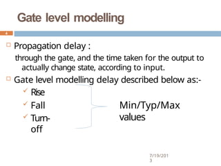
Propagation delay :
through the gate, and the time taken for the output to
actually change state, according to input.
Gate level modelling delay described below as:-
Rise
Fall
Turn-
off
Min/Typ/Max
values
4
7/19/201
3
5.
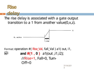
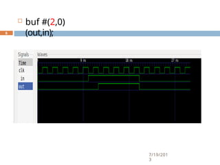
The rise delayis associated with a gate output
transition to a 1 from another value(0,x,z).
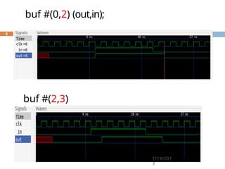
Format: operation #( Rise_Val, fall_Val ) a1( out, i1,
i2);
Ex: and #(1 , 0 ) a1(out ,i1,i2);
//Rise=1, Fall=0, Turn-
Off=0
5
7/19/201
3
Rise
delay
Fall
delay
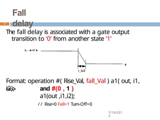
The fall delayis associated with a gate output
transition to ‘0’ from another state ‘1’
Format: operation #( Rise_Val, fall_Val ) a1( out, i1,
i2);
Ex:-> and #(0 , 1 )
a1(out ,i1,i2);
/ / Rise=0 Fall=1 Turn-Off=0
7
7/19/201
3
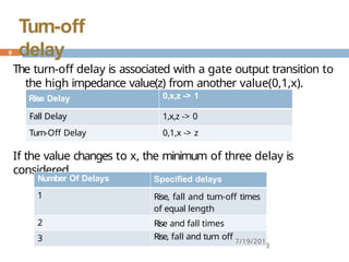
The turn-off delayis associated with a gate output transition to
the high impedance value(z) from another value(0,1,x).
If the value changes to x, the minimum of three delay is
considered.
Rise Delay 0,x,z -> 1
Fall Delay 1,x,z -> 0
Turn-Off Delay 0,1,x -> z
Number Of Delays Specified delays
1 Rise, fall and turn-off times
of equal length
2 Rise and fall times
3 Rise, fall and turn off 7/19/201
3
9
Turn-off
delay
10.
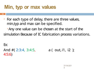
For eachtype of delay, there are three values,
min,typ and max can be specified.
Any one value can be chosen at the start of the
simulation Because of IC fabrication process variations.
7/19/201
3
Ex:
And #( 2:3:4, 3:4:5,
4:5:6)
a ( out, i1, i2 );
10
Min, typ or max values
11.
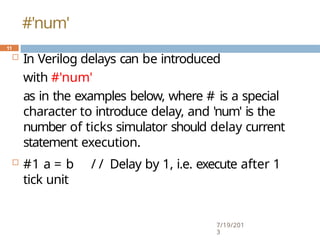
In Verilogdelays can be introduced
with #'num'
as in the examples below, where # is a special
character to introduce delay, and 'num' is the
number of ticks simulator should delay current
statement execution.
7/19/201
3
#1 a = b / / Delay by 1, i.e. execute after 1
tick unit
11
#'num'
12.
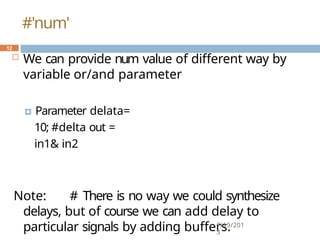
We canprovide num value of different way by
variable or/and parameter
🞑 Parameter delata=
10; #delta out =
in1& in2
Note: # There is no way we could synthesize
delays, but of course we can add delay to
particular signals by adding buffers.
7/19/201
3
12
#'num'
13.
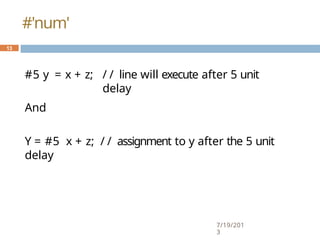
#5 y =x + z;
7/19/201
3
/ / line will execute after 5 unit
delay
And
Y = #5 x + z; / / assignment to y after the 5 unit
delay
13
#'num'
14.
Dataflow Modelling
7/19/201
3
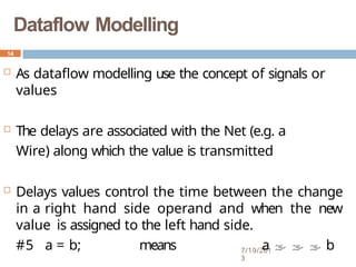
Asdataflow modelling use the concept of signals or
values
The delays are associated with the Net (e.g. a
Wire) along which the value is transmitted
Delays values control the time between the change
in a right hand side operand and when the new
value is assigned to the left hand side.
#5 a = b; means a b
14
15.
Dataflow Modelling
7/19/201
3
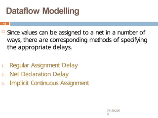
Sincevalues can be assigned to a net in a number of
ways, there are corresponding methods of specifying
the appropriate delays.
1. Regular Assignment Delay
2. Net Declaration Delay
3. Implicit Continuous Assignment
15
16.
Regular Assignment
Delay
T
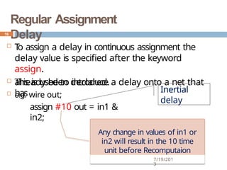
oassign a delay in continuous assignment the
delay value is specified after the keyword
assign.
This is used to introduce a delay onto a net that
has
already been declared.
e.g. wire out;
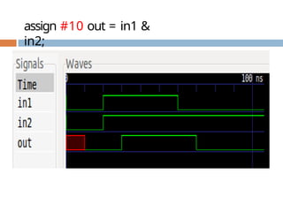
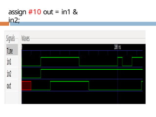
assign #10 out = in1 &
in2;
7/19/201
3
16
Any change in values of in1 or
in2 will result in the 10 time
unit before Recomputaion
Inertial
delay
17.
Net Declaration
Delay
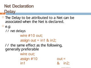
TheDelay to be attributed to a Net can be
associated when the Net is declared.
e.g.
/ / net delays
wire #10 out;
assign out = in1 & in2;
/ / the same effect as the following,
generally preferable
wire out;
assign #10 out =
in1 & in2;
17
Implicit Continuous Assignment
7/19/201
3
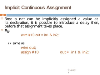
Since a net can be implicitly assigned a value at
its declaration, it is possible to introduce a delay then,
before that assignment takes place.
E.g.
wire #10 out = in1 & in2;
/ / same as
wire out;
assign #10 out = in1 & in2;
20
21.
Inertial
delay
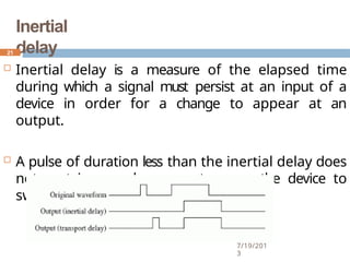
Inertial delayis a measure of the elapsed time
during which a signal must persist at an input of a
device in order for a change to appear at an
output.
A pulse of duration less than the inertial delay does
not contain enough energy to cause the device to
switch.
21
7/19/201
3
22.
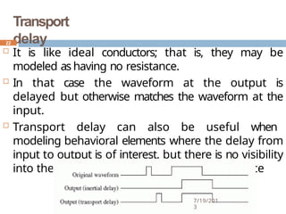
Transport
delay
It islike ideal conductors; that is, they may be
modeled as having no resistance.
In that case the waveform at the output is
delayed but otherwise matches the waveform at the
input.
Transport delay can also be useful when
modeling behavioral elements where the delay from
input to output is of interest, but there is no visibility
into the behavior of delays internal to the device
22
7/19/201
3
REGULAR DELAY CONTROL
7/19/201
3
Regular delay control is used when a non
–zero delay is specified to the left of a
procedural assignment
This is sometimes also referred to as
inter- assignment delay control
Example:#10 q = x+y;
It simply waits for the appropriate
number of timesteps before executing the
command.
24
25.
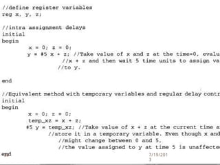
INTRA ASSIGNMENT DELA
Y
7/19/201
3
Instead of specifying delay control to the left
of tha assignment, it is possible to assign a
delay to the right of the assignment operator.
Example: q = #10 x+y;
With this kind of delay ,the value of x+y is
stored at the time that the assignmentis
executed, but this value is not assigned to q
until after the delay period.
25
ZERO DELA
Y
7/19/201
3
Zerodelay is a method to ensure that a
statement is executed last,after all other
statements in that simulation timeare
execcuted.
This is to to elminate race arround conditions.
However if there are multiplezero
delay statements,the order between
them is nondeterministic.
EX:#0 x=1
28
29.
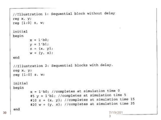
SEQENTIAL BLOCKS
7/19/201
3
Thekeywords begin and end are used to
group statements into seqential blocks.
A statement is executed only after its
preceeding statement completes execution.
29
P
ARALLEL BLOCKS
7/19/201
3
Parallelblocks, specified by keywords fork
and join,provide intresting simulation
features.
Statements in a parallel block are
executed concurrently.
Ordering of statements is controlled by
delay or event control assigned to each
statement.
31