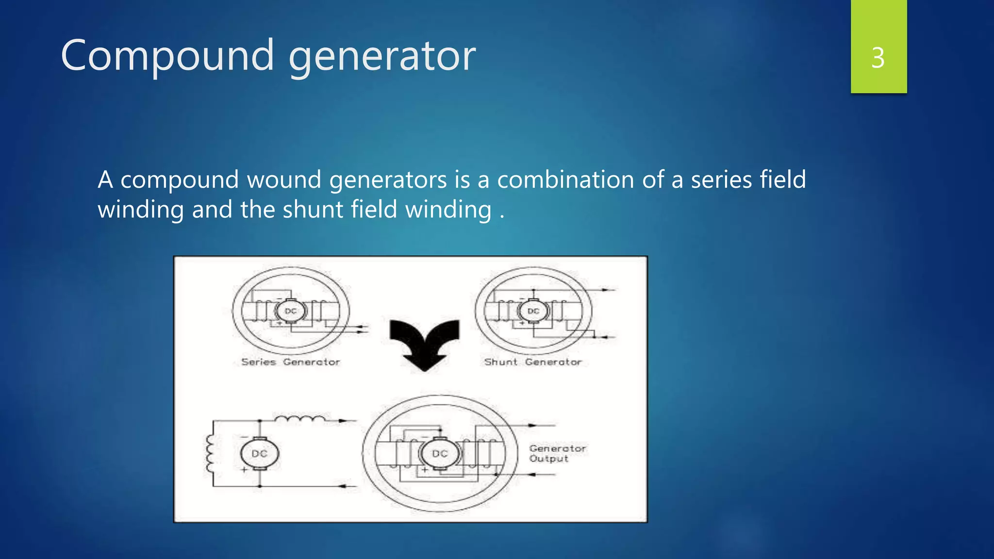
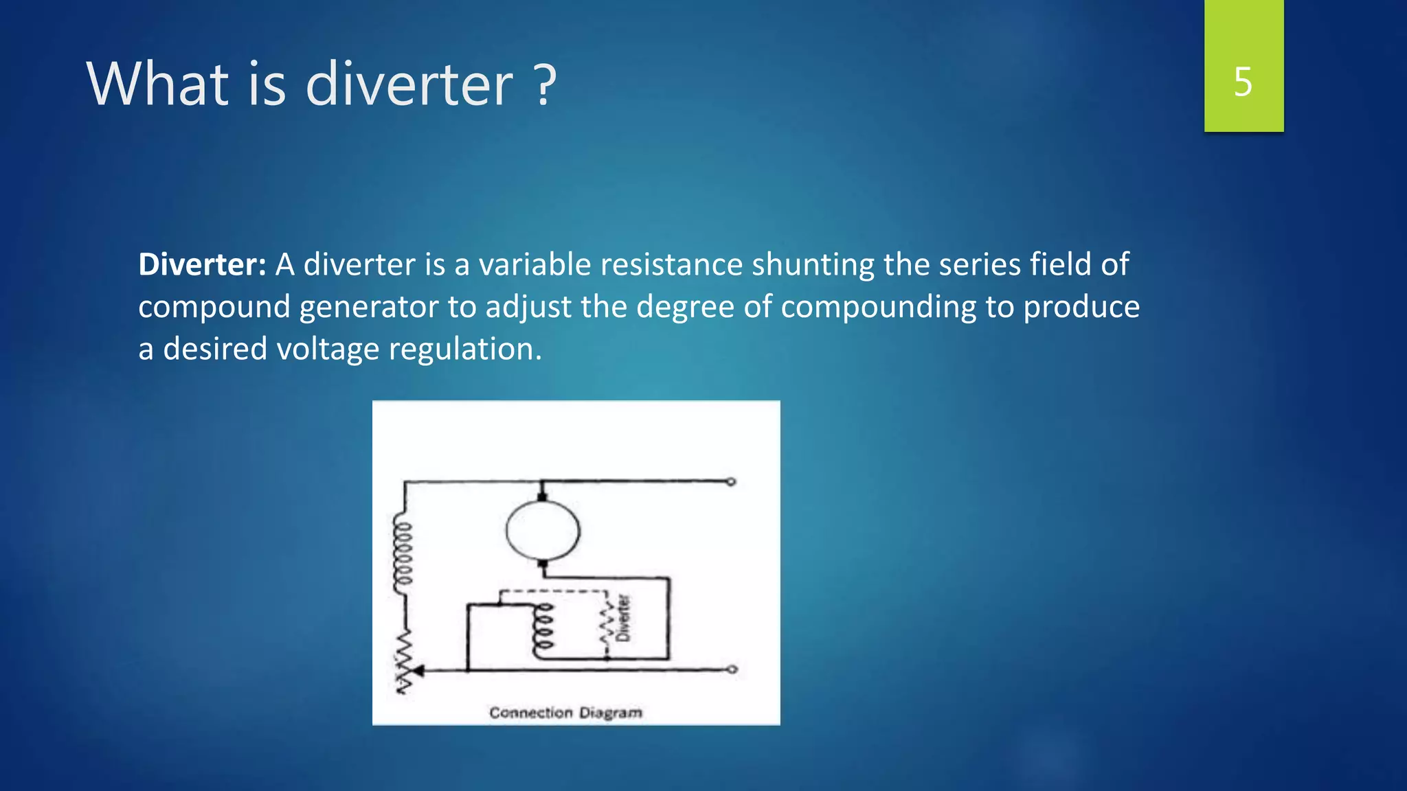
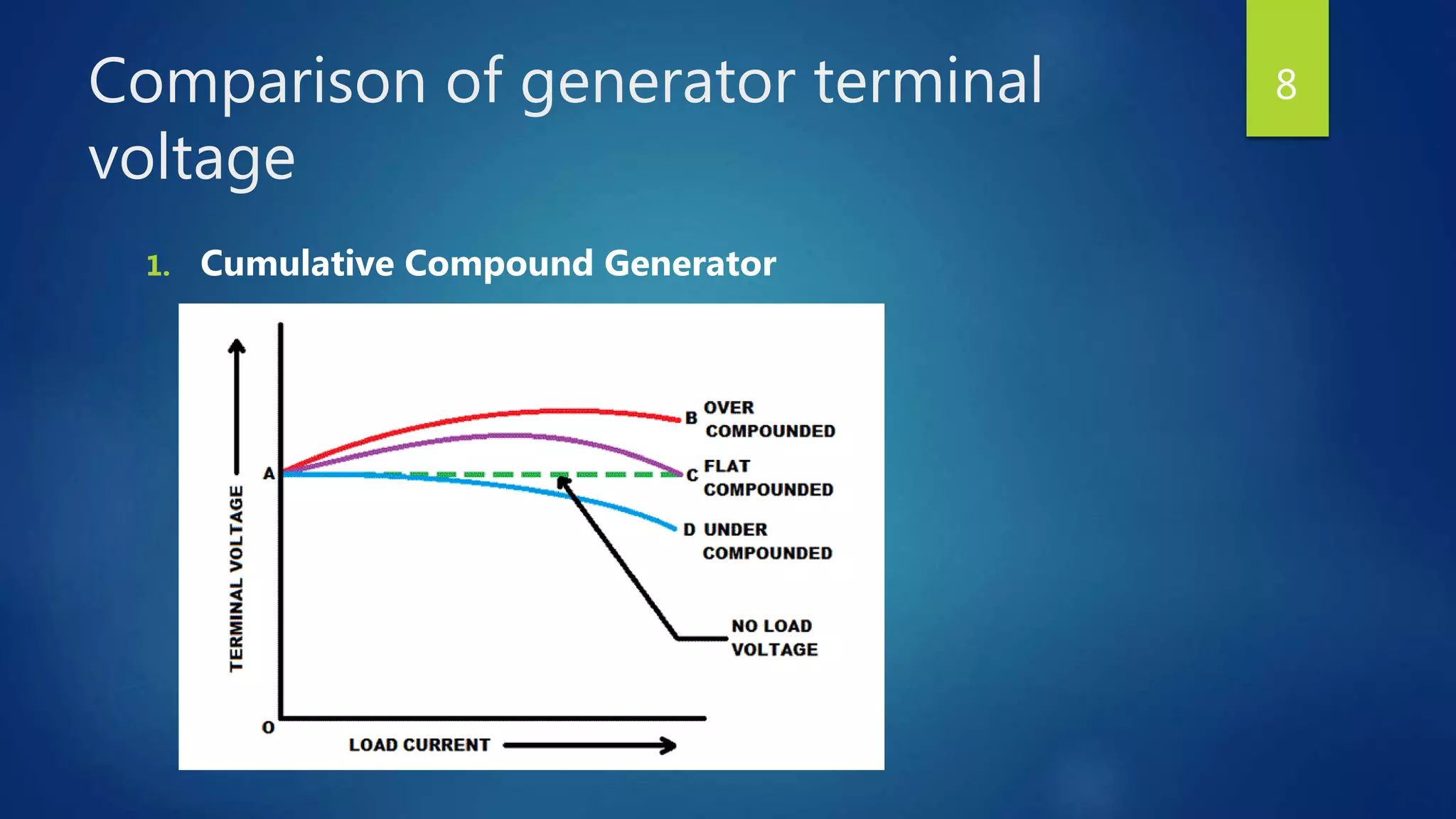
Synchronous generators operate on the principle of electromagnetic induction. They have a stationary armature winding and a rotating field winding supplied by a direct current source. It is advantageous to have the field winding on the rotor and armature winding on the stator because it allows for easier insulation of the high voltage winding and direct connection to the load. The frequency of the induced voltage depends on the number of rotor poles and its rotational speed. Armature reaction is the effect of the armature magnetic field on the main rotor field, distorting or strengthening it depending on the load power factor.
1) The internal generated voltage (EA) in a synchronous generator is different from the output voltage (Vφ) due to armature reaction, self-inductance, and resistance of the stator coils.
2) Armature reaction, caused by the distortion of the air-gap magnetic field by the stator current, is the largest effect. It can be modeled by an inductor in series with EA.
3) The full equivalent circuit model of a 3-phase synchronous generator includes a DC power source for the rotor field, and a per-phase equivalent circuit with EA in series with resistance and inductance to represent the combined effects of armature reaction and self-inductance.
This document provides an overview of DC machines, including their construction, principles of operation, and characteristics. It discusses DC machines functioning as generators and motors. Key points include:
- DC machines can operate as generators, converting mechanical energy to electrical energy, or motors, converting electrical energy to mechanical energy.
- The main components are the stator (stationary part) and rotor (rotating part).
- In generator operation, relative motion between the magnetic field and armature windings induces an electromotive force (emf) based on Faraday's law of induction.
- In motor operation, current passing through the armature windings in a magnetic field experiences an electromagnetic force based on the left-hand
This 3-page document describes an experiment to separate the different losses in a DC shunt motor, including friction, windage, hysteresis, and eddy current losses. It provides an introduction to the theoretical background, outlines the experimental procedure and apparatus used, includes sample data collection in a table, shows calculations to determine the individual loss coefficients, and lists the conclusions. The goal is to measure the losses at different motor speeds and excitations in order to calculate the separate contributions of each loss type based on their speed and field current dependencies.
This document provides information about direct current (DC) motors, including:
- The three main types of DC motors: shunt wound, series wound, and separately excited and their characteristics.
- The principles of operation, construction, and torque-speed characteristics of DC motors.
- How to calculate torque, speed, induced emf, and other parameters for DC motors.
- Applications of the different DC motor types.
- Circuit diagrams and equations for analyzing DC motor performance.
Synchronous Generator, Alternator, construction of alternator,synchronous machines,working of synchronous generator,introduction to synchronous machines,AC machines
The document discusses electric motors and their operation. It describes how electric motors convert electrical energy into mechanical energy by using magnetic fields to generate torque that produces rotation. The speed of a motor can be controlled by adjusting the magnetic field strength or the voltage applied. When a motor operates, it simultaneously acts as a generator producing a counter EMF that limits the current flow. Starters are used to control motor starting by adding resistance that is gradually reduced as the motor speeds up to limit excessive starting currents.
Synchronous generators are the majority source of commercial electrical energy. They are commonly used to convert the mechanical power output of steam turbines, gas turbines, reciprocating engines and hydro turbines into electrical power for the grid.
The document discusses the construction and operation of synchronous generators. It describes how a synchronous generator works by applying a DC current to the rotor to create a rotating magnetic field, which induces a 3-phase voltage in the stator windings. It also discusses the rotor, field windings, armature windings, brushless excitation systems, equivalent circuits, phasor diagrams, and the effects of load changes on generators operating alone or connected in parallel.
Synchronous machines have two sets of windings - a three-phase armature winding on the stationary stator and a DC field winding on the rotating rotor. The rotor can have either a salient pole or cylindrical structure. Large generators use brushless excitation systems to avoid maintenance issues associated with slip rings and brushes. Excitation is provided by a small AC generator (brushless exciter) mounted on the stator whose output is rectified to supply DC current to the main field winding. Proper cooling is required to dissipate heat generated in the windings.
This document discusses cumulatively compounded DC generators. It defines this type of generator as one where the series and shunt fields are connected so their magnetomotive forces add together. The key points covered include: the circuit diagram, dot convention, formulas for terminal voltage, how the voltage characteristics change based on load and level of compounding, using a diverter resistor to achieve different characteristics, and applications like lighting where constant voltage is important.
DC generators convert mechanical energy into direct current electricity through the principle of dynamically induced electromotive force (emf). They have a rotor with coils that spin inside a stationary magnetic field produced by poles. Commutation is needed to change the alternating current induced in the coils to direct current, which involves using brushes and commutator segments. Methods to improve commutation include using resistance or interpoles to neutralize reactance voltage. DC generators are now less common but still used to provide excitation to alternators or in locomotives for regenerative braking. DC motors are used where variable speed or high starting torque is required, such as in cranes, compressors or tractions systems.
A DC generator converts mechanical energy to DC electrical energy using electromagnetic induction. It has two main parts - a rotor that rotates within a stator. As the rotor cuts the magnetic field in the stator, an alternating voltage is induced in the rotor windings. A commutator is used to convert the alternating voltage to direct voltage that can be used to power loads. The characteristics of a DC generator include its open circuit characteristic showing the relationship between generated voltage and field current, and its external characteristic showing the relationship between terminal voltage and load current.
This document discusses power system stability and microgrids. It defines power system stability and classifies it into several types including rotor angle stability, voltage stability, and frequency stability. It also discusses microgrids, their interconnection to main grids for availability and economic benefits, and methods for connecting microgrids using switchgear or static switches. In conclusion, it states that power system stability is important for normal operation and can be improved through devices like capacitors and FACTS controllers, and that microgrids satisfy local loads while reducing transmission losses through local renewable generation.
Working of synchronous machine, Construction of synchronous machine, Types o...Self-employed
Subject : AC Machine
Topic: Working of synchronous machine, Construction of
synchronous machine, Types of synchronous machine,
Application of synchronous machine
The document provides an introduction to DC motors, including:
1) A DC motor converts electrical energy to mechanical energy using electricity and a magnetic field to produce torque that rotates the rotor and provides mechanical work.
2) It consists of an armature mounted in bearings, stationary field coils, and a commutator and brushes. The armature conductors interact with the magnetic field to produce rotation.
3) There are three main types - series wound motors which have high starting torque, shunt wound motors which have low starting torque but constant speed, and compound wound motors which combine characteristics of the first two.
This document describes a project to control the speed of a single-phase induction motor. It uses components like op-amps, opto-isolators, SCRs, and a potentiometer. An op-amp operates in comparator mode to generate pulses that trigger SCRs connected in series with the motor. This allows adjusting the firing angle to control motor speed or lamp brightness. Single-phase induction motors are widely used because they are inexpensive and can operate from a single-phase power supply.
1) DC generators convert mechanical energy to electrical energy through Faraday's law of electromagnetic induction. When a conductor moves through a magnetic field, an EMF is induced in the conductor.
2) The main components of a DC generator are the yoke, field electromagnets, armature, commutator, and brushes. The armature is wound with coils and rotates within the magnetic field produced by the field electromagnets to generate an EMF.
3) As the armature rotates, the commutator and brushes are used to periodically reverse the direction of current in the external circuit, thereby producing direct current. Losses in the generator arise from copper, iron, and mechanical components
This document provides an overview of direct current (DC) machines. It discusses the construction and operating principles of DC generators and DC motors. The key components of a DC machine include the armature, commutator, and field windings. The armature rotates within the magnetic field produced by the field windings to generate an alternating current, which the commutator converts to direct current by reversing the electrical connections at the proper times. DC generators are used to convert mechanical energy to electrical energy, while DC motors operate in reverse to convert electrical energy to mechanical motion.
This document contains lecture notes on the fundamentals of electrical machine design from the EE-1352 ELECTRICAL MACHINE DESIGN course. It defines electrical machine design as the creative physical realization of theoretical concepts to produce machines that perform specified tasks with optimum economy and efficiency. The notes discuss basic considerations in developing a design including the design base, specifications, design transfer, and information updating. It also outlines major considerations like lower cost, durability, and meeting performance criteria, as well as limitations in design such as magnetic saturation, temperature rise, insulation, and customer specifications. Finally, it describes the basic structure of electrical machines including the magnetic, electric, dielectric, thermal, and mechanical circuits.
This document discusses DC motors, including their construction, working principle, types, and applications. It describes the key components of a DC motor such as the yoke, poles, field windings, armature, commutator, and brushes. It explains how DC motors work by converting electrical energy from direct current into mechanical energy. It also covers the different types of DC motors like series, shunt, and compound wound motors along with their characteristics. Common applications of DC motors mentioned include use in vehicles, industrial machinery, and household appliances.
Armature reaction is the effect of current flowing in the armature windings on the main field flux in a DC machine. It causes two undesirable effects: 1) a reduction in the main field flux per pole, and 2) distortion of the main field flux wave along the air gap. Armature current produces cross-flux that either aids or weakens the main flux depending on its location. This results in a non-uniform flux distribution and a shift in the magnetic neutral axis in the direction of rotation for a generator and against rotation for a motor. It also causes demagnetization due to magnetic saturation, further reducing the main field flux from its no-load value.
This document discusses different types of single-phase induction motors and how they are made self-starting. It describes the construction and working of a basic single-phase induction motor. Such a motor is not self-starting because it produces an alternating flux that cannot cause rotation on its own. The document then explains various methods used to make single-phase motors self-starting, including split-phase, capacitor-start, and shaded-pole designs. It provides details on how split-phase and capacitor-start motors introduce a phase difference between windings using a starting winding and capacitor, producing a revolving magnetic field that can start the motor.
This document discusses harmonics in electrical circuits. Harmonics are distortions of the fundamental sinusoidal waveform that are caused by non-linear loads like controlled rectifiers, variable speed drives, and solid state controls. Harmonics can cause overheating and inefficiencies in transformers, capacitors, and power sources. They can also cause issues with protective relay devices. Harmonic filters using inductors and capacitors can be used to reduce harmonics by providing an alternative low impedance path for specific harmonic orders. Regular harmonic studies and corrective actions are needed to prevent problems and improve efficiency when modern electronic loads are used.
This document discusses different types of DC generators, including series, shunt, and compound generators. It provides the following key details:
1. Series generators have a rising voltage characteristic where voltage increases with load, but voltage starts decreasing at high loads due to armature reaction demagnetizing effects.
2. Shunt generators have a constant voltage characteristic, but voltage decreases slightly with increasing load due to armature reaction and armature drop. Adding a few series field coils can make the voltage substantially constant or rising.
3. Compound generators have both shunt and series field windings, allowing their external characteristics to be adjusted to compensate for line voltage drops. Flat-compound generators aim for constant voltage,
A DC motor converts electrical energy into mechanical energy through electromagnetic induction. When a current-carrying conductor is placed in a magnetic field, it experiences a mechanical force. In a DC motor, this force causes the armature conductors to rotate, producing torque. The motor's magnetic field is produced by a field winding and direct current is supplied by an external DC power source. A three-point starter is used to gradually reduce armature current and limit sparking during startup as motor speed increases and back EMF rises.
This document summarizes the principles and operation of an induction generator. It explains that an induction generator operates when the rotor spins faster than synchronous speed, inducing a current in the stator. Reactive power is required from an external capacitor bank to generate a rotating magnetic field. Induction generators are simpler and cheaper than other generators but have lower efficiency and cannot independently regulate voltage levels. Their applications include use in variable-speed wind turbines and dynamic braking systems.
The document discusses induction generators, including their principle of operation, reactive power requirements, and applications. An induction generator operates when its rotor spins faster than synchronous speed, inducing currents to flow and generating power. It requires an external power source to produce a rotating magnetic field, such as a capacitor bank. Induction generators have advantages of being mechanically simple and rugged compared to other generator types. Their main applications are in wind turbines and dynamic braking systems due to their ability to operate over a range of speeds.
The document provides an outline and introduction to DC machines. It discusses the construction and basic parts of DC machines including the stator and rotor. It explains the principle of operation for both DC generators and DC motors. It discusses armature reaction, commutation, and characteristics of DC motors. It also covers the equivalent circuits of DC generators and motors and provides examples of calculating speed and induced emf in DC machines operating as generators and motors.
This presentation is about the whole pricipal about DC machine. It explain the various important parts of dc machine.It tells about how many types of losses are present in DC machine.
This document provides information about electrical generators and DC motors. It discusses:
1. The principle of electrical generators, which convert mechanical energy into electrical energy by inducing voltage in conductors moving through a magnetic field according to Faraday's law of induction.
2. Key parts of generators including a magnetic field and conductors that move to cut the magnetic flux.
3. Types of DC generators including separately excited, shunt wound, series wound, and compound wound generators and their characteristics.
4. The principle of DC motors, which convert electrical energy into mechanical energy by applying a current to a conductor in a magnetic field, producing motion. DC motors can function interchangeably as motors or generators.
5
The document describes the symbolic representation and methods of excitation for DC generators. It discusses separately excited, self-excited, shunt, series, and compound generator types. Key points include:
- DC generators use an electromagnet with a field winding to produce a magnetic field for operation. The field winding is excited either separately using an external DC supply, or self-excited using the generator's own output voltage.
- In a self-excited generator, residual magnetism induces a small voltage to initially power the field winding and build the voltage up to its rated level.
- Shunt, series, and compound generators differ in how their field windings are connected in relation to the armature
This document provides an overview of synchronous generators, including:
- Their construction with rotating field poles and stationary armature windings.
- Their synchronous speed is determined by electrical frequency and number of poles.
- Their internal generated voltage EA is proportional to flux and speed of rotation.
- Their equivalent circuit model accounts for voltage drops due to armature reaction, inductance, and resistance.
- Phasor diagrams illustrate the relationship between EA, terminal voltage, and current under different load power factors.
- Tests are described to determine the open-circuit characteristic and synchronous reactance.
This document discusses power factor in electrical circuits. It defines power factor as the cosine of the angle between the voltage and current. A lagging power factor occurs when the current lags the voltage in an inductive circuit, while a leading power factor occurs when the current leads the voltage in a capacitive circuit. Low power factors can be caused by inductive loads like motors and have negative effects like increased line losses. Common methods to improve power factor include adding static capacitors, using phase advancers for motors, or installing synchronous condensers. The power triangle diagram is also used to illustrate the relationships between active power, reactive power, and apparent power as it relates to power factor.
The document discusses induction generators. It explains that an induction generator operates when an induction motor runs above synchronous speed, causing the rotor to spin faster than synchronous speed with negative slip. It operates similarly to an induction motor but delivers power to a load instead of drawing power. Reactive power must be supplied by a capacitor bank to develop the rotating magnetic field since induction generators are not self-excited. Induction generators have advantages of simple and rugged construction but disadvantages of lower efficiency and inability to regulate voltage without external sources. They are well suited for variable speed applications like wind turbines.
1) A DC generator converts mechanical energy to electrical energy through electromagnetic induction. It produces direct current and is used on light aircraft to power electrical loads and charge batteries.
2) The major components are a frame, rotating armature, and brush assembly. The frame supports the magnetic field windings and other parts. The armature has wire coils wound around an iron core and a commutator to transfer voltage.
3) Generators operate by transforming mechanical energy from rotation into electrical energy via magnets and the rotating armature. Slip rings and brushes transfer this energy from the rotating part to stationary aircraft loads. Proper maintenance is required to ensure security, clean connections and components, and check for issues like worn br
This document discusses synchronous motors and provides information on:
- The key differences between synchronous motors and induction motors, including excitation type, speed, starting capability, and efficiency.
- The advantages of synchronous motors such as ability to operate at lagging or leading power factor and disadvantages like higher cost and need for external excitation.
- The equivalent circuit model of a cylindrical rotor synchronous motor and voltage equation.
- The operation of a synchronous motor at no load and under loaded conditions, explaining how an increase in load causes the rotor to lag the stator by the load angle to draw more current.
- Phasor diagrams showing the voltage and current relationships under lagging and leading power factor operation.
- An example numerical
1) A synchronous generator produces AC voltage through induction in its stator windings caused by a rotating magnetic field generated by its rotor. The rotor contains field windings energized by DC current to produce the magnetic field.
2) The internal generated voltage of the generator depends on its rotational speed and magnetic flux. However, armature reaction and impedance effects cause the terminal voltage to differ from the internal voltage under load conditions.
3) Equivalent circuits are used to model synchronous generators, representing the internal generated voltage and impedance effects. Phasor diagrams illustrate the relationship between voltages and currents under different load power factors.
1) Generators are usually operated in parallel to supply larger loads and increase reliability.
2) For safe paralleling of generators, their voltages, frequencies, and phase sequences must be matched and their phase angles nearly equal.
3) The oncoming generator's frequency is set slightly higher than the running system's to minimize power transients when they connect.
This document summarizes a research paper that models and simulates the behavior of a Doubly Fed Induction Generator (DFIG) during faulty grid conditions using Matlab. It describes how a three-phase fault is created using a fault block, and the converter connected to the rotor is disconnected and the rotor is shorted by dump resistances after the fault occurs. The paper presents the normal and faulty operating equivalent circuits of the DFIG. It also describes the Matlab simulation model developed, including blocks for the DFIG and dump resistor protection. Simulation results are shown graphically comparing stator current with time during a 0.2 to 0.3 second fault period.
This document summarizes a study that models and simulates the behavior of a Doubly Fed Induction Generator (DFIG) during faulty grid conditions. It describes how a three-phase fault was created in MATLAB Simulink and the converter connected to the DFIG rotor was disconnected and a dump resistor was used instead. Equivalent circuits were developed to model the DFIG's behavior during normal and faulty operation. Simulation results are presented showing the stator current, voltage, rotor current and voltage responses during a fault when the dump resistor protection is activated. The study aims to understand and analyze the protections used for DFIGs during faults to limit short circuit currents.
This document summarizes a research paper that models and simulates the behavior of a Doubly Fed Induction Generator (DFIG) during faulty grid conditions using Matlab. It describes how a three-phase fault is created using a fault block, and the converter connected to the rotor is disconnected and the rotor is shorted by dump resistances after the fault occurs. The paper presents the normal and faulty operating equivalent circuits of the DFIG. It also describes the Matlab simulation model developed, including blocks for the DFIG and dump resistor protection. Simulation results are shown graphically for the stator current during a 0.2 to 0.3 second fault period.
This document discusses DC generators, which convert mechanical energy into direct current electrical energy. It begins by introducing generators and distinguishing them from motors. It then explains the basic principles of DC generators, including Faraday's laws of induction. The key components of a DC generator are described, including the field windings, armature, and commutator. The document discusses how DC generators work by inducing current in the armature coils as they pass through the magnetic field. Finally, it outlines different types of DC generators classified by their field excitation and winding connections, and provides some examples of their applications.
CHINA’S GEO-ECONOMIC OUTREACH IN CENTRAL ASIAN COUNTRIES AND FUTURE PROSPECTjpsjournal1
The rivalry between prominent international actors for dominance over Central Asia's hydrocarbon
reserves and the ancient silk trade route, along with China's diplomatic endeavours in the area, has been
referred to as the "New Great Game." This research centres on the power struggle, considering
geopolitical, geostrategic, and geoeconomic variables. Topics including trade, political hegemony, oil
politics, and conventional and nontraditional security are all explored and explained by the researcher.
Using Mackinder's Heartland, Spykman Rimland, and Hegemonic Stability theories, examines China's role
in Central Asia. This study adheres to the empirical epistemological method and has taken care of
objectivity. This study analyze primary and secondary research documents critically to elaborate role of
china’s geo economic outreach in central Asian countries and its future prospect. China is thriving in trade,
pipeline politics, and winning states, according to this study, thanks to important instruments like the
Shanghai Cooperation Organisation and the Belt and Road Economic Initiative. According to this study,
China is seeing significant success in commerce, pipeline politics, and gaining influence on other
governments. This success may be attributed to the effective utilisation of key tools such as the Shanghai
Cooperation Organisation and the Belt and Road Economic Initiative.
Embedded machine learning-based road conditions and driving behavior monitoringIJECEIAES
Car accident rates have increased in recent years, resulting in losses in human lives, properties, and other financial costs. An embedded machine learning-based system is developed to address this critical issue. The system can monitor road conditions, detect driving patterns, and identify aggressive driving behaviors. The system is based on neural networks trained on a comprehensive dataset of driving events, driving styles, and road conditions. The system effectively detects potential risks and helps mitigate the frequency and impact of accidents. The primary goal is to ensure the safety of drivers and vehicles. Collecting data involved gathering information on three key road events: normal street and normal drive, speed bumps, circular yellow speed bumps, and three aggressive driving actions: sudden start, sudden stop, and sudden entry. The gathered data is processed and analyzed using a machine learning system designed for limited power and memory devices. The developed system resulted in 91.9% accuracy, 93.6% precision, and 92% recall. The achieved inference time on an Arduino Nano 33 BLE Sense with a 32-bit CPU running at 64 MHz is 34 ms and requires 2.6 kB peak RAM and 139.9 kB program flash memory, making it suitable for resource-constrained embedded systems.
KuberTENes Birthday Bash Guadalajara - K8sGPT first impressionsVictor Morales
K8sGPT is a tool that analyzes and diagnoses Kubernetes clusters. This presentation was used to share the requirements and dependencies to deploy K8sGPT in a local environment.
A SYSTEMATIC RISK ASSESSMENT APPROACH FOR SECURING THE SMART IRRIGATION SYSTEMSIJNSA Journal
The smart irrigation system represents an innovative approach to optimize water usage in agricultural and landscaping practices. The integration of cutting-edge technologies, including sensors, actuators, and data analysis, empowers this system to provide accurate monitoring and control of irrigation processes by leveraging real-time environmental conditions. The main objective of a smart irrigation system is to optimize water efficiency, minimize expenses, and foster the adoption of sustainable water management methods. This paper conducts a systematic risk assessment by exploring the key components/assets and their functionalities in the smart irrigation system. The crucial role of sensors in gathering data on soil moisture, weather patterns, and plant well-being is emphasized in this system. These sensors enable intelligent decision-making in irrigation scheduling and water distribution, leading to enhanced water efficiency and sustainable water management practices. Actuators enable automated control of irrigation devices, ensuring precise and targeted water delivery to plants. Additionally, the paper addresses the potential threat and vulnerabilities associated with smart irrigation systems. It discusses limitations of the system, such as power constraints and computational capabilities, and calculates the potential security risks. The paper suggests possible risk treatment methods for effective secure system operation. In conclusion, the paper emphasizes the significant benefits of implementing smart irrigation systems, including improved water conservation, increased crop yield, and reduced environmental impact. Additionally, based on the security analysis conducted, the paper recommends the implementation of countermeasures and security approaches to address vulnerabilities and ensure the integrity and reliability of the system. By incorporating these measures, smart irrigation technology can revolutionize water management practices in agriculture, promoting sustainability, resource efficiency, and safeguarding against potential security threats.
International Conference on NLP, Artificial Intelligence, Machine Learning an...gerogepatton
International Conference on NLP, Artificial Intelligence, Machine Learning and Applications (NLAIM 2024) offers a premier global platform for exchanging insights and findings in the theory, methodology, and applications of NLP, Artificial Intelligence, Machine Learning, and their applications. The conference seeks substantial contributions across all key domains of NLP, Artificial Intelligence, Machine Learning, and their practical applications, aiming to foster both theoretical advancements and real-world implementations. With a focus on facilitating collaboration between researchers and practitioners from academia and industry, the conference serves as a nexus for sharing the latest developments in the field.
Harnessing WebAssembly for Real-time Stateless Streaming PipelinesChristina Lin
Traditionally, dealing with real-time data pipelines has involved significant overhead, even for straightforward tasks like data transformation or masking. However, in this talk, we’ll venture into the dynamic realm of WebAssembly (WASM) and discover how it can revolutionize the creation of stateless streaming pipelines within a Kafka (Redpanda) broker. These pipelines are adept at managing low-latency, high-data-volume scenarios.
Literature Review Basics and Understanding Reference Management.pptxDr Ramhari Poudyal
Three-day training on academic research focuses on analytical tools at United Technical College, supported by the University Grant Commission, Nepal. 24-26 May 2024
A review on techniques and modelling methodologies used for checking electrom...nooriasukmaningtyas
The proper function of the integrated circuit (IC) in an inhibiting electromagnetic environment has always been a serious concern throughout the decades of revolution in the world of electronics, from disjunct devices to today’s integrated circuit technology, where billions of transistors are combined on a single chip. The automotive industry and smart vehicles in particular, are confronting design issues such as being prone to electromagnetic interference (EMI). Electronic control devices calculate incorrect outputs because of EMI and sensors give misleading values which can prove fatal in case of automotives. In this paper, the authors have non exhaustively tried to review research work concerned with the investigation of EMI in ICs and prediction of this EMI using various modelling methodologies and measurement setups.
Optimizing Gradle Builds - Gradle DPE Tour Berlin 2024Sinan KOZAK
Sinan from the Delivery Hero mobile infrastructure engineering team shares a deep dive into performance acceleration with Gradle build cache optimizations. Sinan shares their journey into solving complex build-cache problems that affect Gradle builds. By understanding the challenges and solutions found in our journey, we aim to demonstrate the possibilities for faster builds. The case study reveals how overlapping outputs and cache misconfigurations led to significant increases in build times, especially as the project scaled up with numerous modules using Paparazzi tests. The journey from diagnosing to defeating cache issues offers invaluable lessons on maintaining cache integrity without sacrificing functionality.
2008 BUILDING CONSTRUCTION Illustrated - Ching Chapter 02 The Building.pdf
Degree of compounding
1. Degree of Compounding
Submitted by:
Md. Ziaul Haque
ID: 555181028
Submitted to:
Najmin Ara Sultana
Lecturer, Department of EEE
Hamdard University Bangladesh
1
2. Index
Compound generator
Types of compound generator
What is diverter ?
Comparison of generator terminal voltage
A. Cumulative Compound Generator
1. Over compound
2. Flat compound
3. Under compound
B. Differential Compound Generator
2
3. Compound generator
A compound wound generators is a combination of a series field
winding and the shunt field winding .
3
4. Types of compound generator
There are two types of compound generator-
Cumulative Compound Generator : When the series field
assists the shunt field, generator is said to be Cumulative
Compound Generator.
Differential Compound Generator: When the series field
opposes the shunt field, generator is said to be Differential
Compound Wound Generator.
4
5. What is diverter ?
Diverter: A diverter is a variable resistance shunting the series field of
compound generator to adjust the degree of compounding to produce
a desired voltage regulation.
5
9. Continue…….
Over compound : An over-compound generator is one
whose terminal voltage rises with the application of load so
that its full-load voltage exceeds its no-load voltage.
Flat-compound : A flat compound generator has a load-
voltage characteristic in which the no-load and full-load
voltages are equal.
9
10. Continue………
Under compound : In Under compound generator the
terminal voltage is higher than shunt generator but lower than
flat compound generator.
10
11. Continue…….
Differential Compound Generator :
When the series field winding creating
magnetic flux that opposes the flux
created by shunt field. The net flux
cut by the armature conductors is less
than the flux at no load resulting in a
lower induced voltage.
11