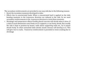
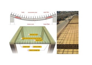
the ladakh protest in leh ladakh 2024 sonam wangchuk.pptx
slabs ppt.pdf
1.
2. •Fig shows a simply
supported slab supported
on two walls on opposite
sides.
•There are only two walls,
and they are parallel to the
Y axis.
•There are no walls parallel
to the X axis.
3. Deflected shape of slab
•We can see that the shape of the
deflected slab is such that, it
forms a part of a cylinder.
•The axis of this cylinder is
parallel to the Y axis. ie., parallel
to the supporting walls.
•The load on the slab is
transferred to the two
supporting walls.
•So this type of slab bends only
in one direction, and is called a
‘One-way slab’.
4. Fig. shows a simply
supported slab
supported on walls
on all the four
sides.
5. Deflected shape of the slab.
•We can see that the shape of
the deflected slab is such that,
it forms a part of a sphere.
•The load on the slab is
transferred to all the four
supporting walls.
•So this type of slab bends in
both X and Y directions, and is
called a ‘Two-way slab’.
6. •The distance between the
walls parallel to the X axis
has been increased.
•The span parallel to the Y
axis is denoted as ly and the
span parallel to the X axis is
denoted by lx
7. •When load is applied, the slab
deflects. In fig., we can see that
the slab deflects in both X and Y
directions.
•The load on the slab is
transferred to all the four walls.
•But the curvature of the slab in
the Y direction (the longer
direction) is lesser than that in
the X direction.
•As ly increases, more and more
load will get transferred in the
other X direction, and it will
begin to act like a One-way slab
8. •So we need a reference point, above which we classify the slab as a one-way slab, and below
which we classify it as a two-way slab.
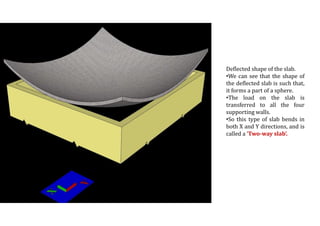
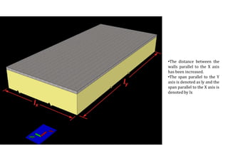
•For this, we take the ratio: [ longer span / shorter span ], which is equal to ly / lx .
•If ly / lx > 2, the slab is a one-way slab.
•Other wise it is a two way slab.
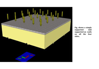
•It should be noted that this is applicable only for slabs supported on all the four sides. Also, the
longer span should be taken as ly, and the shorter span should be taken as lx .
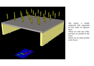
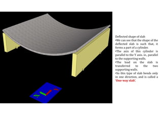
•This method is to be used only on those slabs which are resting on walls on all the four sides. If
there are walls only on the opposite sides, the load transfer will occur in that direction only, and
it will be a one way slab.
9. • One way slab can be compared to a beam:
• We divide the slab into a number of strips as
shown in the fig.
• The strips extend from one support to the other.
Each strip has a width of 1m. Each of these strips
act as individual beams. So each of these beams
will have a width of 1m and a total depth D,
where D is the total depth of the slab.
• Assuming that only 'uniformly distributed load' is
acting on the slab, and that the slab is of uniform
thickness, all these strips are identical. We can
take any one of them for analysis and design.
10. • To design the one way slab, we take any one strip of 1m
width.
• We want the load per unit 'length' of this strip
• This load load per unit 'length' that we require, is same as the
load per unit 'area' of the slab.
• Self weight of the slab in the unit area: - - - - (1)
• Volume of the concrete block in the unit area = 1m x1m x'D'm
= 'D'm3. ('D' should be in meters.)
• So weight of the concrete block in unit area = Dx25kN/m3 =
25DkN/m2
• Self wt. of finishes: - - - - (2)
• Usually it varies from 0.5 to 1.0 kN/m2.
• Live loads: - - - - (3)
• This can be obtained from IS code 875. This load depends
upon the nature of use of the building. (Residential, office,
storage purpose etc.,). Usually it is given in kN/m2
• All the relevant clauses of the code must be considered in
arriving at the appropriate value of the loads to be used in the
design.
• Characteristic load is obtained. We must multiply it by the
load factor to obtain the factored load.
11. Transverse moments in slabs
There is a difference between the bending of a beam and the bending of a strip of
slab.
First let us consider the bending of a beam.
When the beam is subjected to a sagging moment, the portion above the NA is
under compression. Due to this compression, there will be a lateral expansion for
the portion above the NA. This is due to the poisson effect. In the same manner, the
portion below the NA is under tension, and hence there will be a lateral contraction.
So after bending, the cross section of the beam will have a nearly trapezoidal shape
Now let us consider the strip of slab.
In this case, the expansion above the NA and the contraction below the NA is
prevented by the strips on the two sides of the design strip.
So the portion above the NA will experience a lateral compressive reaction from the
adjacent strips, so that the lateral expansion is prevented.
The portion below the NA will experience a lateral tensile reaction from the
adjacent strips, so that the lateral contraction is prevented. These lateral forces will
give rise to secondary moments in the transverse direction as shown in the fig
12. • For slabs, pt = 0.4 to 0.5 kt = 1.25
• Simply supported slabs : (l/d)actual ≤ 20 x 1.25 ⇒ (l/d)actual ≤ 25. So d that we actually provide in
the final slab should be greater than or equal to l/25.
• For continuous slabs, we can write:
• (l/d)actual ≤ 26 x 1.25 ⇒ (l/d)actual ≤ 32.5. So d that we actually provide in the final slab should be
greater than or equal to l/32.5.≈ l/32
• Minimum spacing to be provided between the bars of a slab:
• The clear space provided between parallel reinforcing bars should not be less than the minimum
value specified in cl 26.3.2 of the code.
• 3d
• 300mm
13. The secondary reinforcements are provided in one way slab due to the following reasons
• Resist the secondary moments developed in slabs:
• Effects due to concentrated loads: When a concentrated load is applied on the slab,
bending moments in the transverse direction are induced in the slab. So we want
secondary reinforcements in the transverse direction to resist these moments.
• Shrinkage and temperature effects Freshly placed concrete will shrink when it dries. If
a slab of usual dimensions rests freely on it's supports, it can freely shrink. But usually
the slab is kept in position by beams, walls above supporting walls etc., So it cannot
shrink freely. So when restrained slabs shrink, tensile stresses will develop in it. This
will give rise to cracks. Transverse reinforcement is provided to resist cracking due to
shrinkage