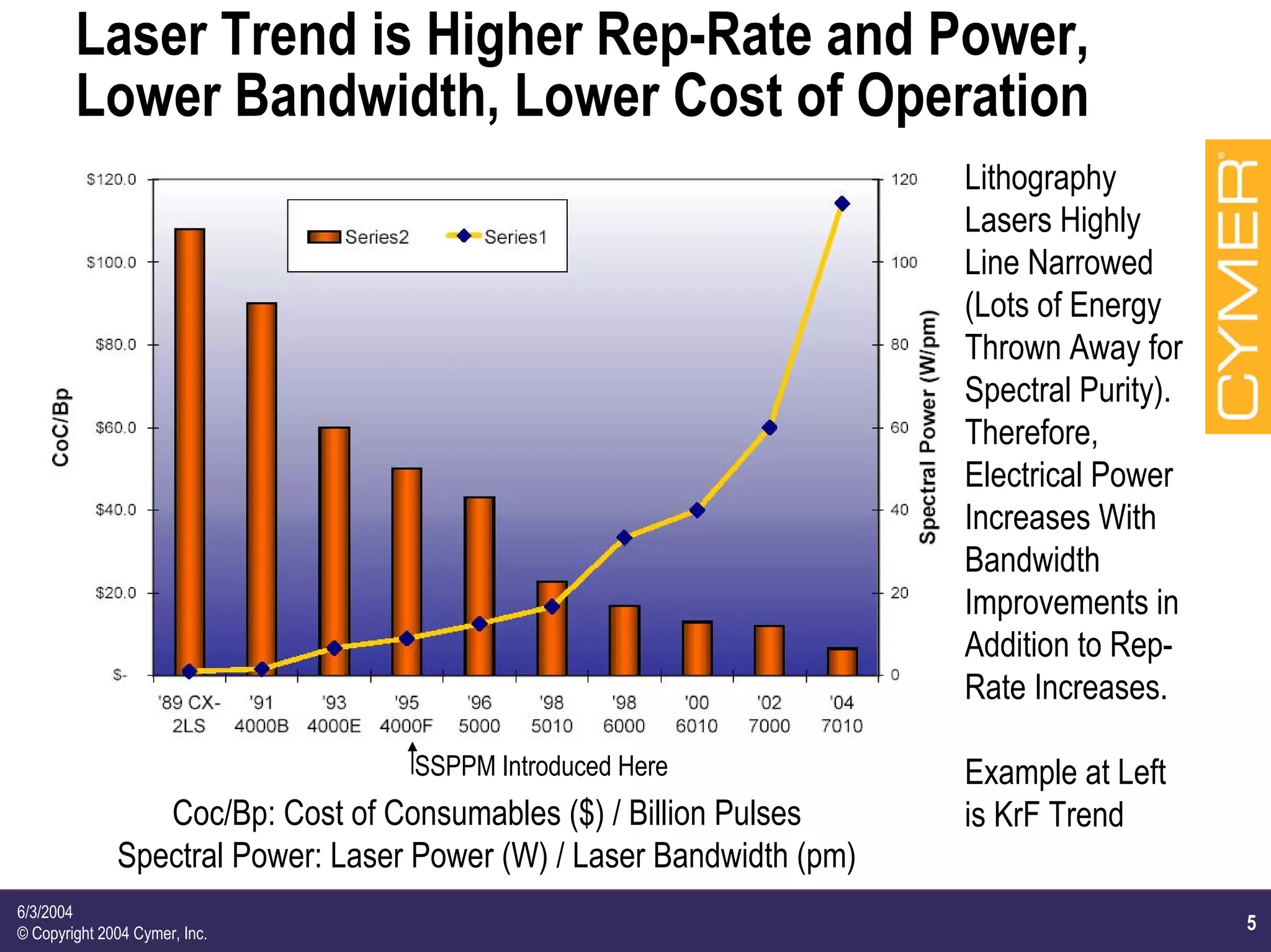
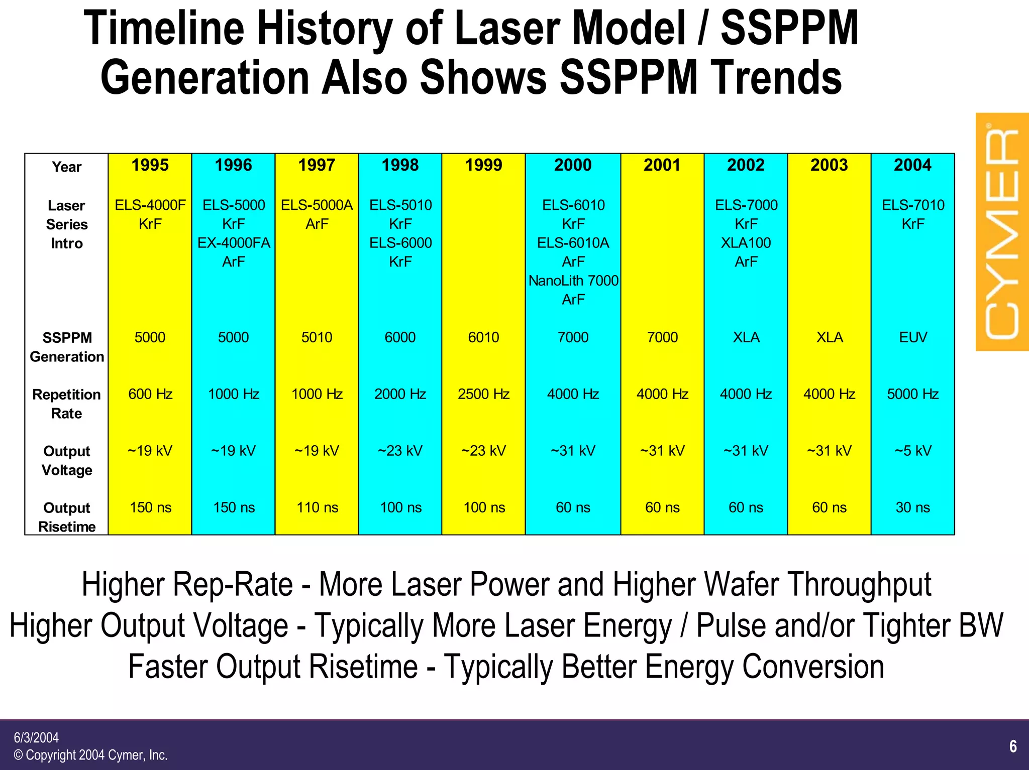
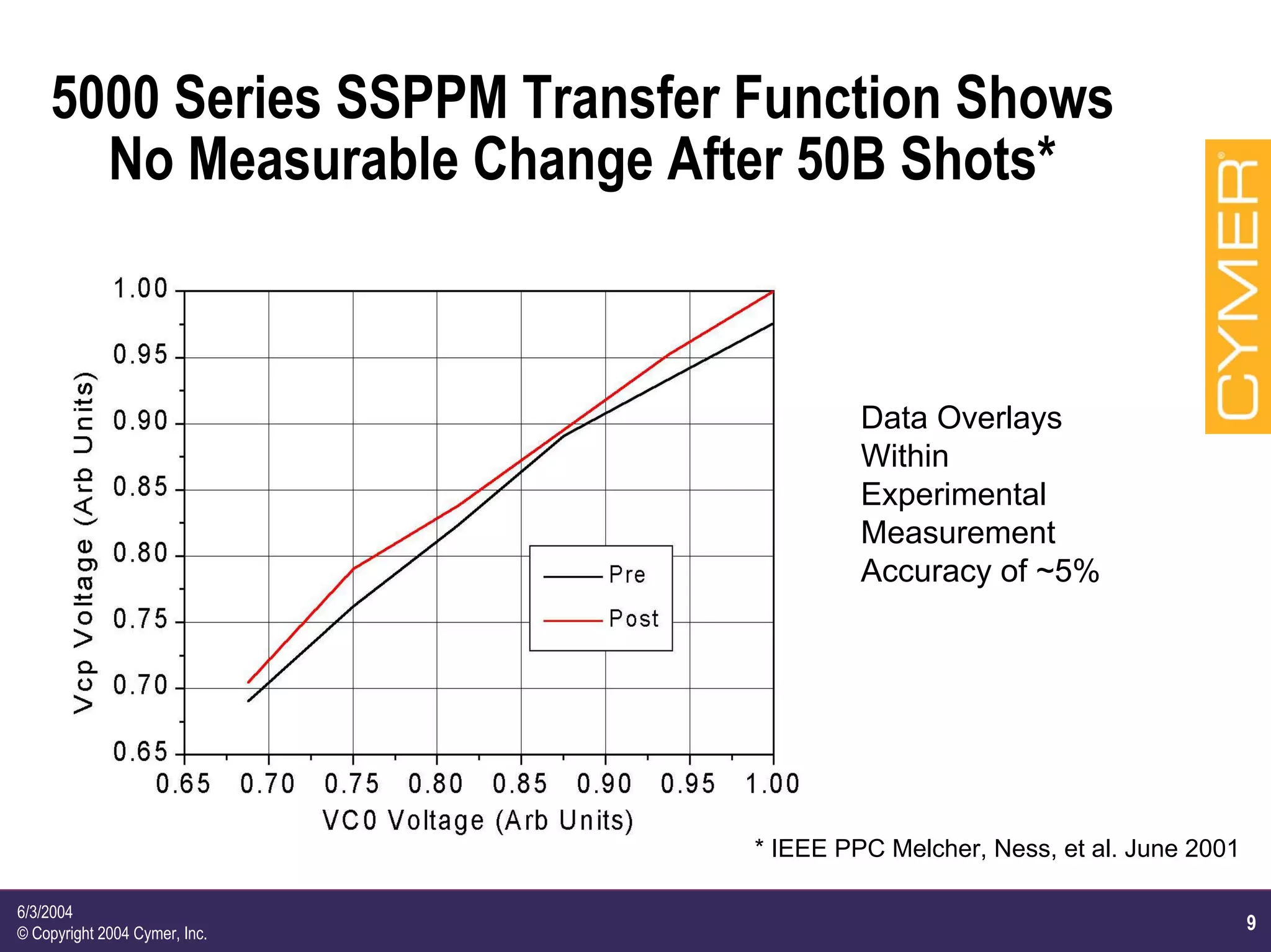
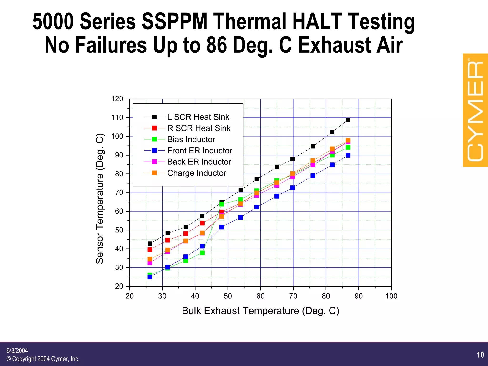
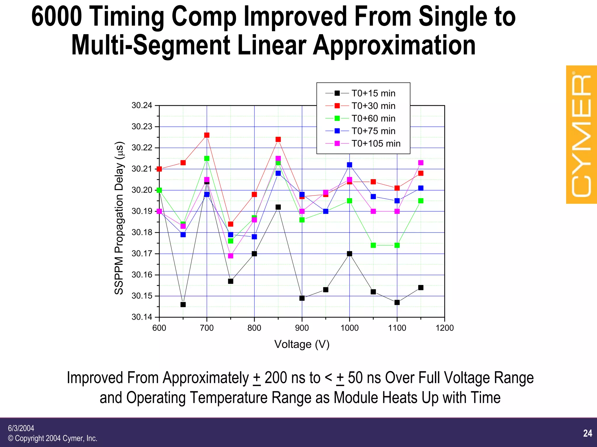
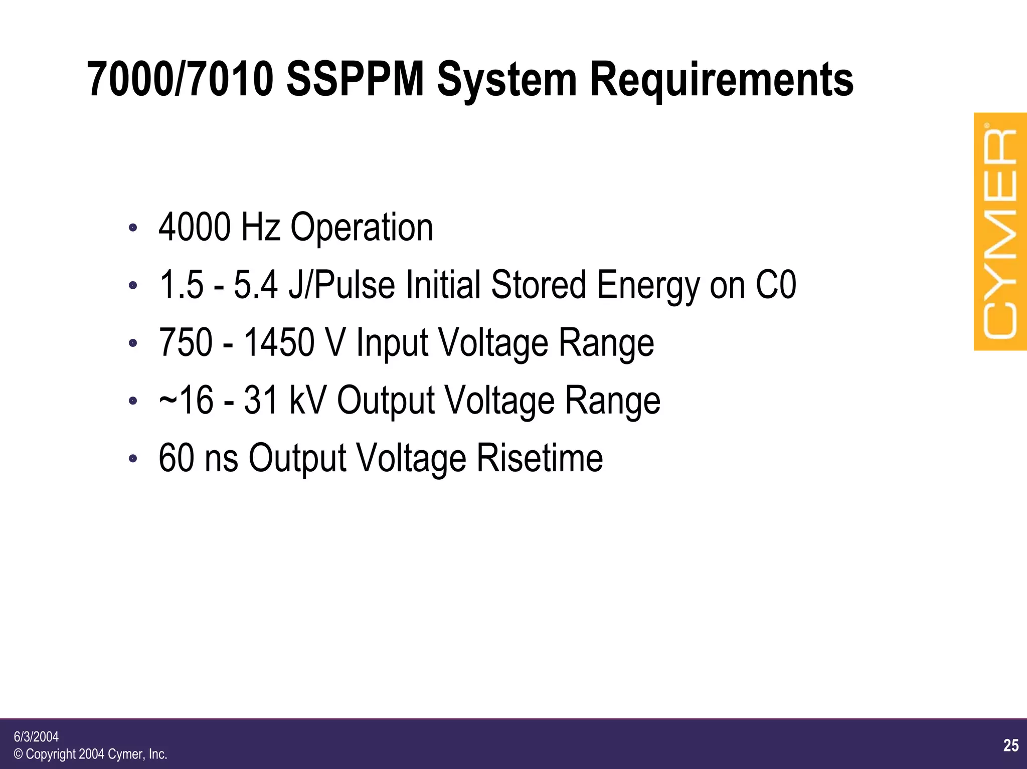
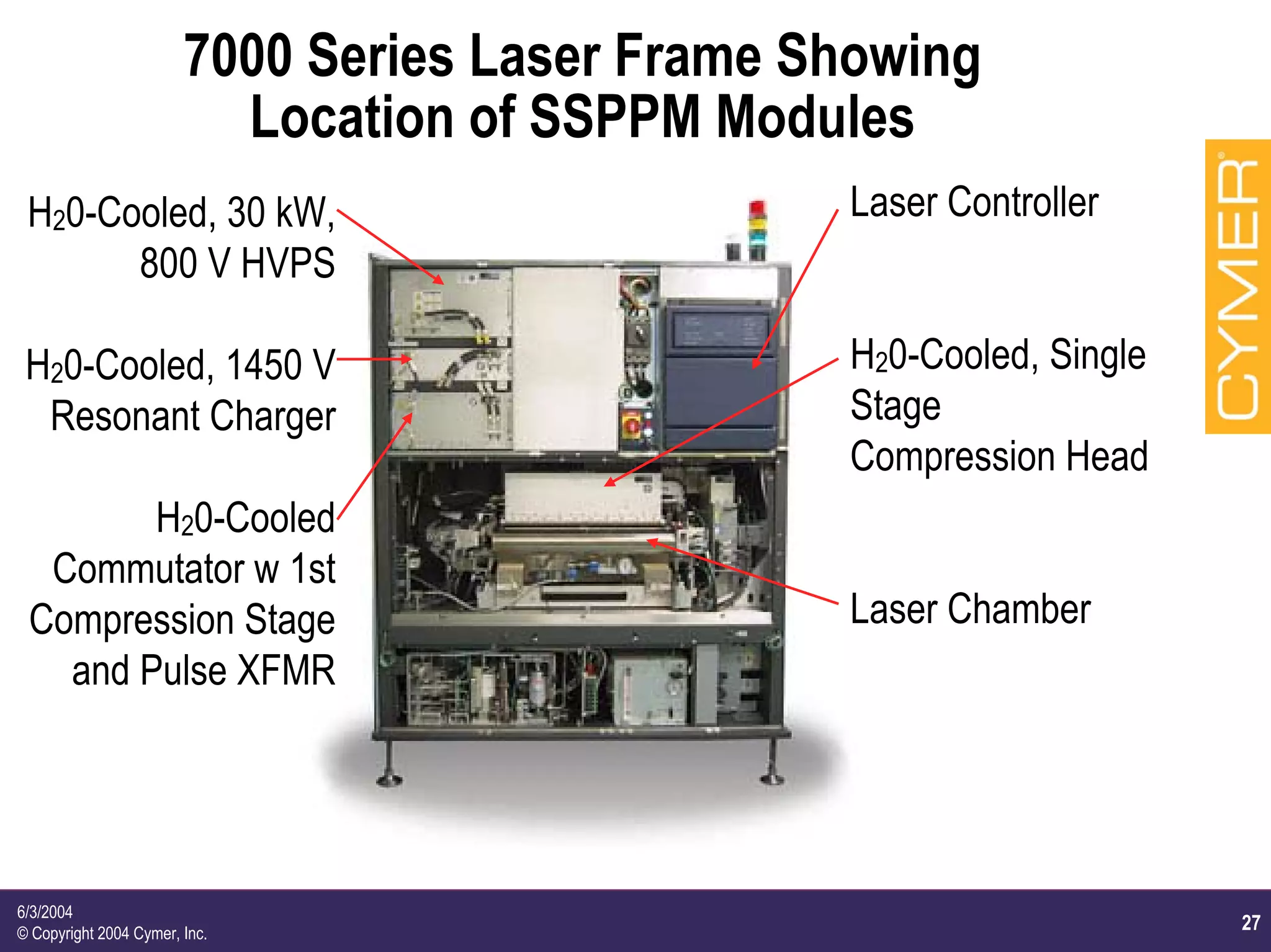
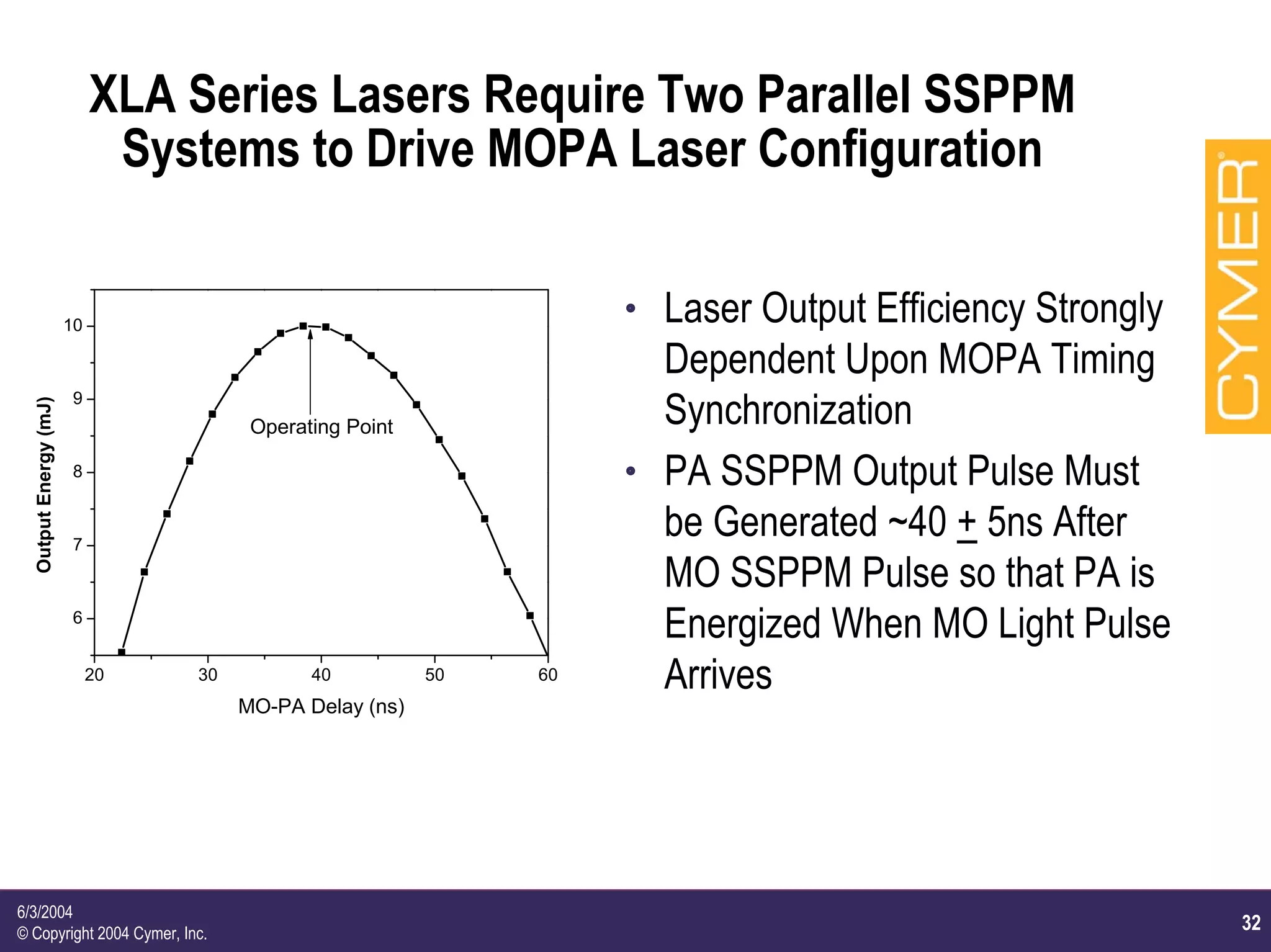
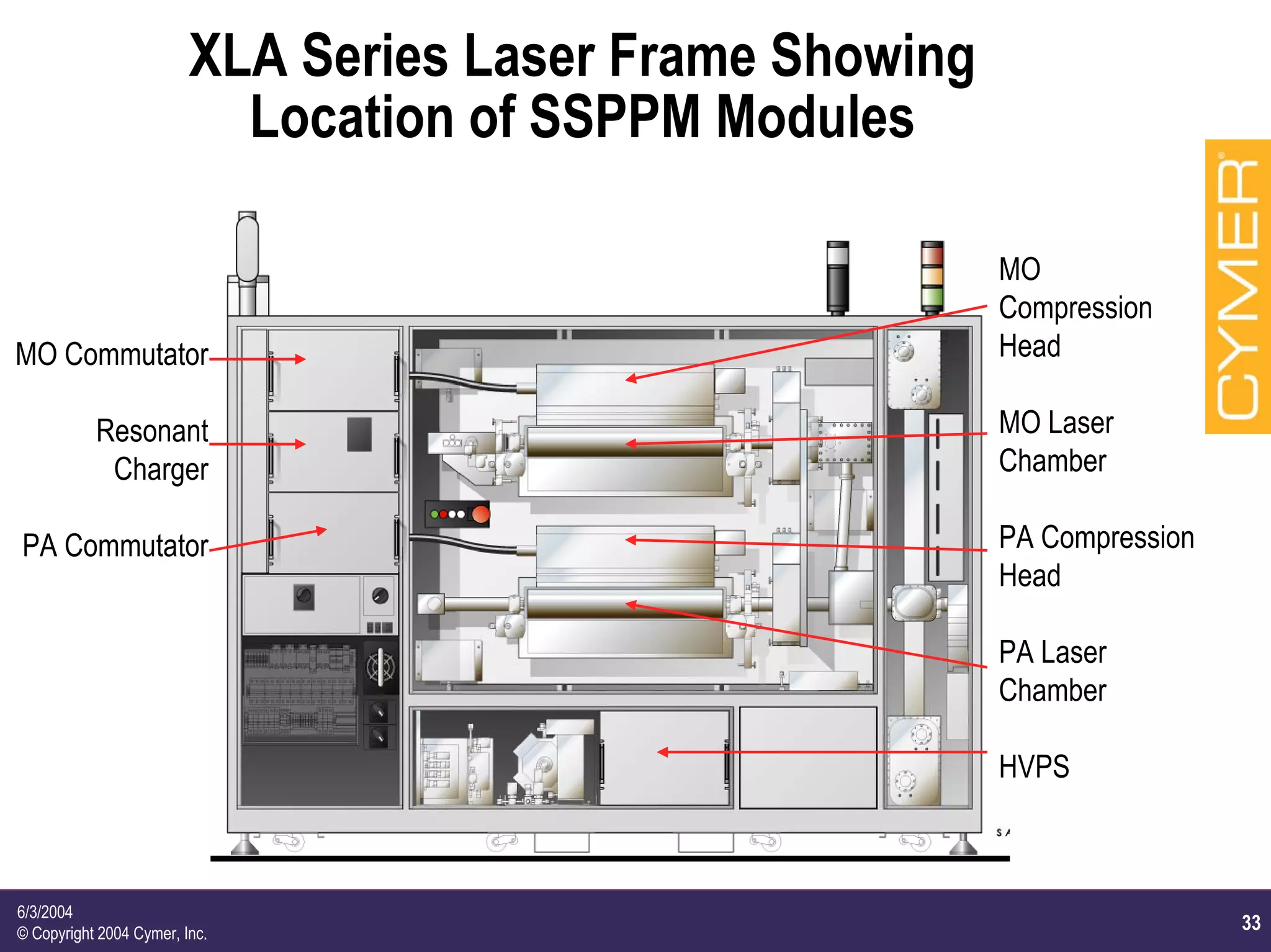
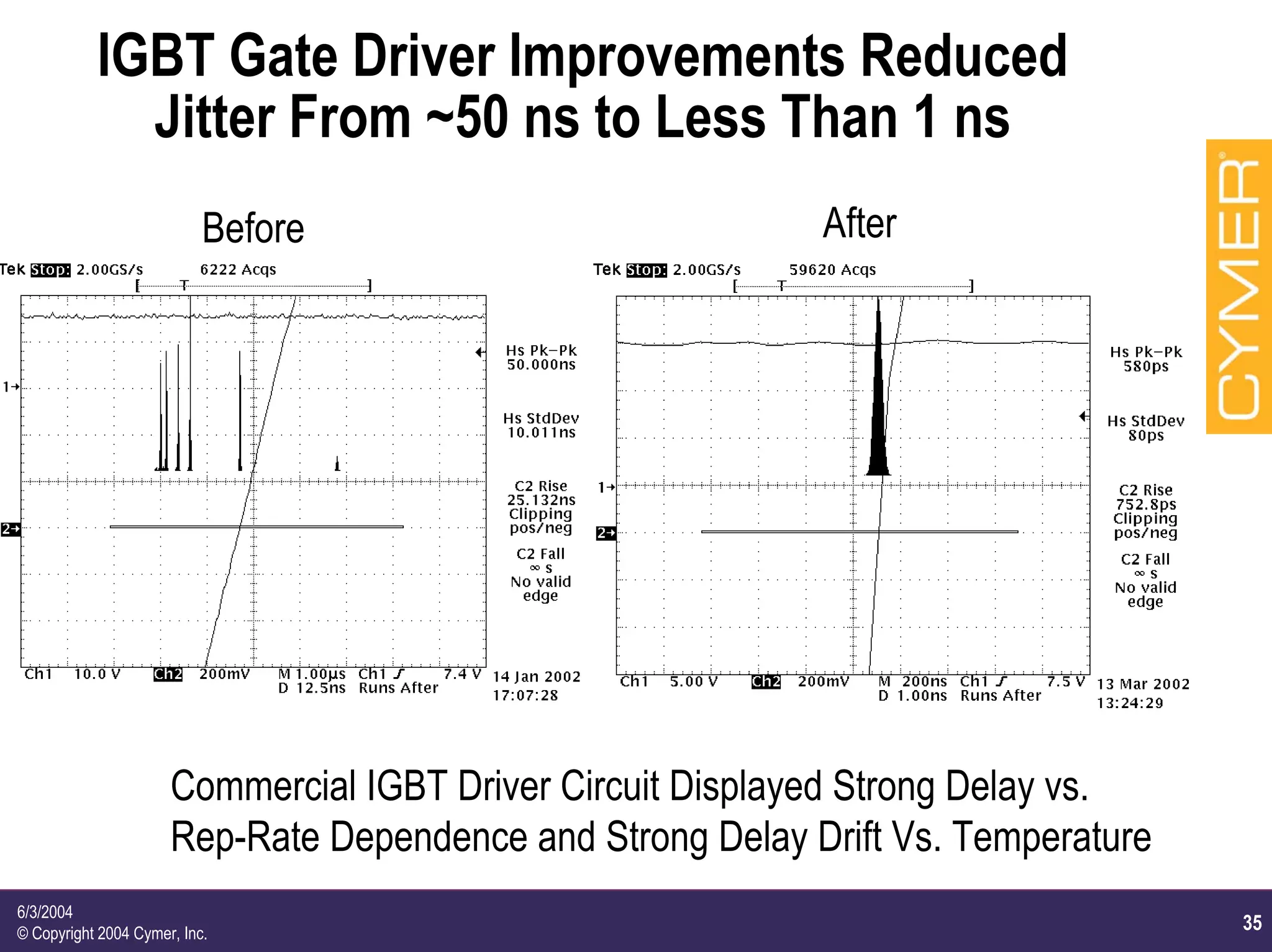
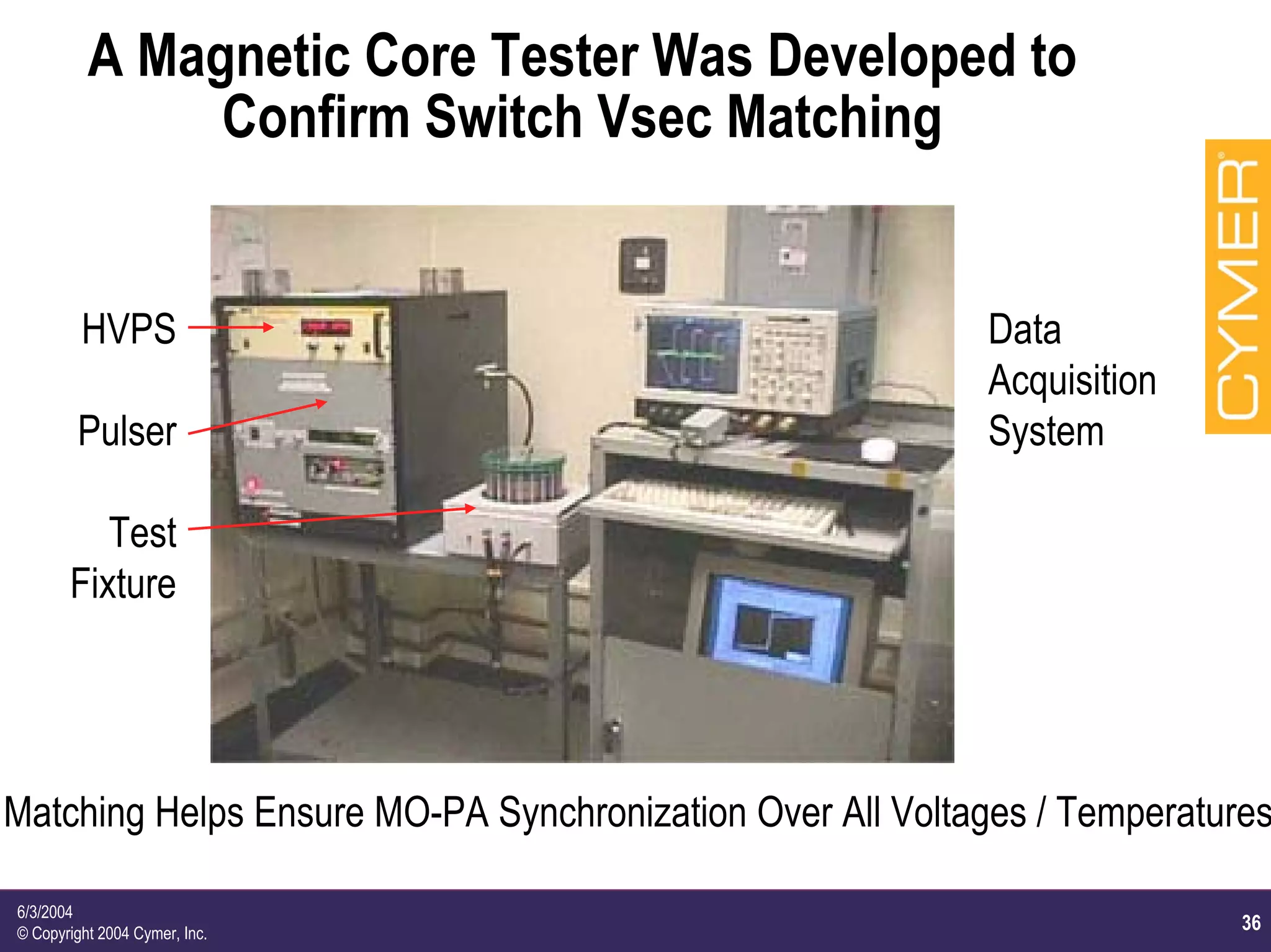
6/3/2004
© Copyright 2004 Cymer, Inc.
A Decade of Solid State Pulsed
Power Development at CYMER Inc.
R. Ness, P. Melcher, G. Ferguson, and C. Huang
CYMER Inc., 17075 Thornmint Court,
San Diego, CA, 92127, USA
2004 Power Modulator Conference, May 23-26, 2004
2
6/3/2004
© Copyright 2004 Cymer, Inc.
Outline
h Background and History of Cymer
h Pulse power requirements for lithography light-sources
h High volume manufacturing requirements issues
h Survey of Cymer’s solid state pulse power
h Past, present and future
h Specifications
h Design
h Lessons learned
3
6/3/2004
© Copyright 2004 Cymer, Inc.
CYMER Background and History
h World's Leading Supplier of Excimer Lasers for
Semiconductor Photolithography
h Founded in 1986 and Headquartered in San Diego,
CA with ~800 Current Worldwide Employees
h Primary Customers are ASML, Nikon, and Canon
but Lasers are Utilized in Virtually Every
Semiconductor Fab (Fabrication) Facility
h 2282 CYMER Lasers Installed Worldwide as of Q1
2004 (Virtually All with Solid State Pulsed Power)
4
6/3/2004
© Copyright 2004 Cymer, Inc.
Solid State Pulsed Power Module (SSPPM)
Technology Introduced at CYMER in Early '90s
h Components developed by Dan Birx Through a DARPA SBIR
Contract
h Significant Advantages for Lithography Laser Over Prior
Technology
h "Infinite" Lifetime Compared to Thyratron Based Units
h Energy Recovery of Pulse Reflected from Laser Load Increases Chamber
Lifetime Significantly (at Least ~70%)
h Less Impact on Semiconductor Fab Operation (Fewer
Repairs/Replacements, No Warm-up Time Needed, etc.)
h No Pre-Fires Causing Missing Pulses and Wafer Level Rework
h Laser Cost of Ownership (CoO) Therefore Significantly Reduced
h First SSPPM Unit Shipped in Production Laser in 1995
h ~3800 SSPPM Module Sets Manufactured Since Then
5
6/3/2004
© Copyright 2004 Cymer, Inc.
Laser Trend is Higher Rep-Rate and Power,
Lower Bandwidth, Lower Cost of Operation
SSPPM Introduced Here
Lithography
Lasers Highly
Line Narrowed
(Lots of Energy
Thrown Away for
Spectral Purity).
Therefore,
Electrical Power
Increases With
Bandwidth
Improvements in
Addition to Rep-
Rate Increases.
Example at Left
is KrF TrendCoc/Bp: Cost of Consumables ($) / Billion Pulses
Spectral Power: Laser Power (W) / Laser Bandwidth (pm)
6
6/3/2004
© Copyright 2004 Cymer, Inc.
Timeline History of Laser Model / SSPPM
Generation Also Shows SSPPM Trends
Year 1995 1996 1997 1998 1999 2000 2001 2002 2003 2004
Laser ELS-4000F ELS-5000 ELS-5000A ELS-5010 ELS-6010 ELS-7000 ELS-7010
Series KrF KrF ArF KrF KrF KrF KrF
Intro EX-4000FA ELS-6000 ELS-6010A XLA100
ArF KrF ArF ArF
NanoLith 7000
ArF
SSPPM 5000 5000 5010 6000 6010 7000 7000 XLA XLA EUV
Generation
Repetition 600 Hz 1000 Hz 1000 Hz 2000 Hz 2500 Hz 4000 Hz 4000 Hz 4000 Hz 4000 Hz 5000 Hz
Rate
Output ~19 kV ~19 kV ~19 kV ~23 kV ~23 kV ~31 kV ~31 kV ~31 kV ~31 kV ~5 kV
Voltage
Output 150 ns 150 ns 110 ns 100 ns 100 ns 60 ns 60 ns 60 ns 60 ns 30 ns
Risetime
Higher Rep-Rate - More Laser Power and Higher Wafer Throughput
Higher Output Voltage - Typically More Laser Energy / Pulse and/or Tighter BW
Faster Output Risetime - Typically Better Energy Conversion
7
6/3/2004
© Copyright 2004 Cymer, Inc.
A Variety of Issues Existed for Successful
Volume Manufacturing of SSPPM Modules
h Design/Change Management: Detailed Documentation was
Developed:
h Part Specifications
h Piece Part, Sub-Assembly, and Assembly Drawings
h Multi-Level Bills of Material (~800 Line Items)
h Assy and Test Procedures for Sub-Assy and Module Levels
h Supply Chain: Procurement Had to Ramp Up With Parts / New
Vendors
h Manufacturing/QA: Manufacturing Staff was Trained
h Testing: Intermediate and Final Test Stand HW was Set Up
h Logistics: Worldwide Spares Distribution / Stocking was Initiated
8
6/3/2004
© Copyright 2004 Cymer, Inc.
Semiconductor Fab Application Requires
Very Long Lifetime / High Reliability
h ~5 Year Life on Fab Tool Implies Infinite SSPPM
Lifetime (at Least 25 to 50B shots)
h Laser Demonstrates > 99% Total Uptime
h 5000 Series SSPPM Tested for Over 50B Shots
(Over 2.5 Years) With No Signs of Degradation
h HALT Testing (Primarily Thermal) Conducted for
Multiple Generations
h Extensive Thermal Testing Done Prior to Design
Release
9
6/3/2004
© Copyright 2004 Cymer, Inc.
5000 Series SSPPM Transfer Function Shows
No Measurable Change After 50B Shots*
* IEEE PPC Melcher, Ness, et al. June 2001
Data Overlays
Within
Experimental
Measurement
Accuracy of ~5%
10
6/3/2004
© Copyright 2004 Cymer, Inc.
5000 Series SSPPM Thermal HALT Testing
No Failures Up to 86 Deg. C Exhaust Air
20 30 40 50 60 70 80 90 100
20
30
40
50
60
70
80
90
100
110
120
L SCR Heat Sink
R SCR Heat Sink
Bias Inductor
Front ER Inductor
Back ER Inductor
Charge Inductor
SensorTemperature(Deg.C)
Bulk Exhaust Temperature (Deg. C)
11
6/3/2004
© Copyright 2004 Cymer, Inc.
SSPPM Operating Voltage Range is Large
Compared to Many Magnetic Pulse Compressors
h Laser Operating Voltage Varies Significantly
Depending Upon Chamber Life and Gas Conditions
h Typical Range of Laser SSPPM Initial Stored Energy
is ~1.5 to 5.5 J per Pulse
h Complicates SSPPM Magnetic Switch Design
h Timing Compensation Required for Consistent
Propagation Delay Over Entire Voltage Range
12
6/3/2004
© Copyright 2004 Cymer, Inc.
Many Other Issues are Also Important For
This Application in Semiconductor Fab
h Packaging: Module Size Minimized Since Fab Floor Space is
Very Expensive
h Serviceability: Weight and Ease of Troubleshooting Relate to
Potential Field Service and Module Replacement
h Cost: Driving Factor Since it Impacts Profit
h Compliance: Need to Avoid Potential Fab Contaminants
h Minimize Fluid Impregnants Typically Used for HV Insulation
h Use Materials Approved for Fab Use
h Safety: Units Must Also Comply With SEMI, UL, TUV Standards
13
6/3/2004
© Copyright 2004 Cymer, Inc.
5000/5010 SSPPM System Requirements
h 1000 Hz Operation
h 1.5 - 4.0 J/Pulse Initial Stored Energy on C0
h 550 - 800 V Input Voltage Range
h ~12 - 19 kV Output Voltage Range
h 150 ns Output Voltage Risetime (5000)
h 110 ns Output Voltage Risetime (5010)
14
6/3/2004
© Copyright 2004 Cymer, Inc.
5000/5010 Series SSPPM
Electrical Schematic Diagram
Compression HeadCommutator
HVPS
Laser Chamber
h Capacitor Charging Power Supply
h Parallel SCR Switching
h 26X (28X in 5010) Inductive Voltage Adder Transformer
h 3 Stages of Magnetic Pulse Compression
h 10 µs Initial Transfer Down to 150 ns
15
6/3/2004
© Copyright 2004 Cymer, Inc.
5000 Series Laser Frame Showing
Location of SSPPM Modules
(Behind Panel)
1000 V,
6 kJ/sec
HVPS
Air-Cooled
Commutator
w 1st
Compression
Stage and
Pulse XFMR
Laser Controller
2 Stage,
H20-Cooled
Compression
Head
Laser Chamber
16
6/3/2004
© Copyright 2004 Cymer, Inc.
5000 Issues - Minor Problems Resolved During
Initial Manufacturing and Production
h Magnetic Core Production Issues
h Instituted Close Monitoring of Magnetic Core Parameters
to Avoid Unacceptable Components
h Compression Head Cooling
h Added Cold Plate to CH Housing to Cool Switch Cores
and Minimize Loss of ∆B Due to Temp
h HV Cable Connector Problems
h Identified Errors in Commercial Connector Design
17
6/3/2004
© Copyright 2004 Cymer, Inc.
5000 Timing Compensation - Customer
Requires Tight Control of Throughput Delay*
h Stepper/Scanner Manufacturers Require Sync Out
Signal for Their Own Diagnostics
h Trigger-to-Laser Light Must be Constant in Spite of
SSPPM Operation at Different Voltages as Laser
Chamber Ages
h Solution: Sample Final Charging Voltage and
Insert Appropriate Proportional Delay in Low Level
Electronics Prior to SCR Trigger
"Timing Compensation for an Excimer Laser Solid-State Pulsed Power Module (SSPPM)", with D. Johns, et al,
IEEE Transactions on Plasma Science, Volume 28, Number 5, October 2000.
18
6/3/2004
© Copyright 2004 Cymer, Inc.
6000/6010 SSPPM System Requirements
h 2000 Hz Operation (6000)
h 2500 Hz Operation (6010)
h 1.5 - 5.4 J/Pulse Initial Stored Energy on C0
h 600 - 1150 V Input Voltage Range
h ~12 - 23 kV Output Voltage Range
h 100 ns Output Voltage Risetime
19
6/3/2004
© Copyright 2004 Cymer, Inc.
6000/6010 Series SSPPM
Electrical Schematic Diagram
Commutator Compression Head Laser ChamberHVPS
h Capacitor Charging Power Supply
h Parallel IGBT Switching
h 23X Inductive Voltage Adder Transformer
h 2 Stages of Magnetic Pulse Compression
h 5 µs Initial Transfer Down to 100 ns
20
6/3/2004
© Copyright 2004 Cymer, Inc.
6000 Series Laser Frame Showing
Location of SSPPM Modules
(Behind Panel)
1200 V, 14 kJ/sec,
Air-Cooled HVPS
Air-Cooled
Commutator
w 1st Compression
Stage and
Pulse XFMR
Laser Controller
Air-Cooled,
Single Stage Compression
Head
Laser Chamber
21
6/3/2004
© Copyright 2004 Cymer, Inc.
6000 Series SSPPM Uses 2 Stages of Magnetic
Pulse Compression (MPC) Vs. Prior 3 Stage Design
h Maturity of IGBT Technology Allowed Replacement
of SCR and Enabled Faster Commutation Time (C0-
C1 Transfer)
h Faster Commutation Time and Improvement to MPC
Designs Allowed Elimination of One Stage of Pulse
Compression
h Advantages:
h Improved SSPPM Efficiency
h Better Residual Voltage Snubbing
h Improved Manufacturability and Serviceability
22
6/3/2004
© Copyright 2004 Cymer, Inc.
6000 UL/TUV Compliance
Testing Performed at CYMER
h Module Level Certification by NRTLs (Nationally
Recognized Testing Labs)
h Tested to UL 3101-1 and EN 61010-1 Standards
h Includes Detailed Analysis of:
h Construction (Creepage and Clearance)
h Material (Flammability, Electrical Properties, etc.)
h Environmental
h Failure Modes
h Single-Point Failure
h Fault Handling
h Electrical and Thermal
h Isolation and Grounding
23
6/3/2004
© Copyright 2004 Cymer, Inc.
6000 Air/Water Heat Exchanger
h Environmental Control Important to Long-Term
Reliability of Module
h Internal and External Resistance to Direct Water
Cooling
h Compromise w/ Air-to-Water HX
h Advantages:
h Ability to Control Critical Components
h Reduced Need to Cooling Fluid Bath
h Minimize Heat Load to Fab Air Exhaust
24
6/3/2004
© Copyright 2004 Cymer, Inc.
6000 Timing Comp Improved From Single to
Multi-Segment Linear Approximation
600 700 800 900 1000 1100 1200
30.14
30.15
30.16
30.17
30.18
30.19
30.20
30.21
30.22
30.23
30.24
T0+15 min
T0+30 min
T0+60 min
T0+75 min
T0+105 min
SSPPMPropagationDelay(µs)
Voltage (V)
Improved From Approximately + 200 ns to < + 50 ns Over Full Voltage Range
and Operating Temperature Range as Module Heats Up with Time
25
6/3/2004
© Copyright 2004 Cymer, Inc.
7000/7010 SSPPM System Requirements
h 4000 Hz Operation
h 1.5 - 5.4 J/Pulse Initial Stored Energy on C0
h 750 - 1450 V Input Voltage Range
h ~16 - 31 kV Output Voltage Range
h 60 ns Output Voltage Risetime
26
6/3/2004
© Copyright 2004 Cymer, Inc.
7000/7010 Series SSPPM
Electrical Schematic Diagram
HVPS Resonant Charger Commutator Laser ChamberComp
Head
h Resonant Charging Power Supply
h Parallel IGBT Switching
h 25X Inductive Voltage Adder Transformer
h 2 Stages of Magnetic Pulse Compression
h 4 µs Initial Transfer Down to 60 ns
27
6/3/2004
© Copyright 2004 Cymer, Inc.
7000 Series Laser Frame Showing
Location of SSPPM Modules
H20-Cooled, 30 kW,
800 V HVPS
H20-Cooled, 1450 V
Resonant Charger
H20-Cooled
Commutator w 1st
Compression Stage
and Pulse XFMR
Laser Controller
H20-Cooled, Single
Stage
Compression Head
Laser Chamber
28
6/3/2004
© Copyright 2004 Cymer, Inc.
Resonant Charger Technology Replaced Cap
Charging Power Supply for 7000 Series SSPPM
h As Rep-Rate Increases, Inter-Pulse Time Decreases
h Significant Part of Time Required by Controller to
Calculate Voltage for Next Pulse in Constant Energy Mode
h Additional Time Required for Energy Recovery
h As a Result, Time Allowed for Charging Decreasing Faster
Than Rep-Rate Increase - Cap Charger Not Effective
h Solution - Resonant Charging and Simpler HVPS
h Pulse Charging can be Done Very Fast
h HVPS Can Still Deliver Constant Power Flow to Filter Capacitor
Resulting in More Constant AC Power Draw with Fewer
Harmonics
29
6/3/2004
© Copyright 2004 Cymer, Inc.
Water Cooling Implemented for 7000 Series
SSPPM Thermal Management
h Water Cooling Required to Remove Thermal Heat Load
h Implementation Features
h Cold Plate in Commutator for Cooling Semiconductors and
1st Stage Reactor Housing
h Water Tubing Supplied to Cool Output Reactor Housing
h Inductive Isolation of High Voltage Potential
h No Joints Internal to Module
h No Possibility of Leaks Inside Module
30
6/3/2004
© Copyright 2004 Cymer, Inc.
Cooling Water Tubing to Output Magnetic
Switch Housing Inductively Isolated
Solid Tubing Run Inside Chassis Avoids Joints and Leak Potential
Copper Tubing Also Provides Bias Current Return Path
31
6/3/2004
© Copyright 2004 Cymer, Inc.
Laser Design Paradigm Occurs in 2002 at CYMER
as Laser Power and BW Requirements Get Tougher
h Laser Power Traditionally Increased by Rep-Rate Increase
h However, Chamber Blower Power Increasing with Cube of
Rep-Rate (All Else Constant)
h Chamber Acoustics and Tougher BW Complicating Issues
h Optics Issues and Module Lifetimes Also Not Acceptable
h Solution - Two Chamber MOPA Laser
h Low Power Master Oscillator (MO) Which Produces Tight BW
h High Gain Power Amplifier (PA) Which Boosts Output Power
32
6/3/2004
© Copyright 2004 Cymer, Inc.
XLA Series Lasers Require Two Parallel SSPPM
Systems to Drive MOPA Laser Configuration
h Laser Output Efficiency Strongly
Dependent Upon MOPA Timing
Synchronization
h PA SSPPM Output Pulse Must
be Generated ~40 + 5ns After
MO SSPPM Pulse so that PA is
Energized When MO Light Pulse
Arrives20 30 40 50 60
6
7
8
9
10
OutputEnergy(mJ)
MO-PA Delay (ns)
Operating Point
33
6/3/2004
© Copyright 2004 Cymer, Inc.
XLA Series Laser Frame Showing
Location of SSPPM Modules
MO Commutator
Resonant
Charger
PA Commutator
MO
Compression
Head
MO Laser
Chamber
PA Compression
Head
PA Laser
Chamber
HVPS
34
6/3/2004
© Copyright 2004 Cymer, Inc.
XLA SSPPM Electrical Schematic Diagram
HVPS Resonant Charger Commutators Comp
Heads
Laser
Chambers
Common Resonant Charger Drives 2 Parallel SSPPMs for Master
Oscillator and Power Amplifier
35
6/3/2004
© Copyright 2004 Cymer, Inc.
IGBT Gate Driver Improvements Reduced
Jitter From ~50 ns to Less Than 1 ns
AfterBefore
Commercial IGBT Driver Circuit Displayed Strong Delay vs.
Rep-Rate Dependence and Strong Delay Drift Vs. Temperature
36
6/3/2004
© Copyright 2004 Cymer, Inc.
A Magnetic Core Tester Was Developed to
Confirm Switch Vsec Matching
HVPS
Pulser
Test
Fixture
Data
Acquisition
System
Matching Helps Ensure MO-PA Synchronization Over All Voltages / Temperatures
37
6/3/2004
© Copyright 2004 Cymer, Inc.
Cores Are Procured in Matched Sets
Within Range of Target Bsat
V*t=0.18838+0.81162*Bm
(Correlation Coefficient R=0.92)
NormalizedVolt-secondofReactor
Normalized Average Bm of Magnetic Cores
38
6/3/2004
© Copyright 2004 Cymer, Inc.
Kaiser Systems Resonant Charger Pulse-to-Pulse Regulation
Difference Between Max-Min Out of 10 Bursts
1
11
21
31
41
51
61
71
81
91
750
850
950
1050
1150
0
0.01
0.02
0.03
0.04
0.05
0.06
0.07
0.08
0.09
MAX-MIN (%
PULSECOUNT
VOLTAGE
S/N 710018 SPREAD BY PULSE
39
6/3/2004
© Copyright 2004 Cymer, Inc.
XLA Timing Synchronization Held to Less
Than + 2.0 ns Between MO and PA SSPPMs
0
0.5
1
P uls e Index
∆t
MOPA
Error,ns,σ
S igma
0 10 20
P robability, %
0 50 100 150 200 250
-2.5
-2
-1.5
-1
-0.5
0
0.5
1
1.5
2
∆t
MOPA
Error,ns
Chamber S ynch Error, Inernal Energy Control, 4 kHz
Average
Min
Max
Laser
Controller
Handles Long
Term Timing
Changes Due
to Thermal
Drift and/or
Voltage
Changes
40
6/3/2004
© Copyright 2004 Cymer, Inc.
SSPPM Systems Also Being Developed to
Support EUV Lithography Light Sources
Electrodes
Insulator
Pinch
h Dense Plasma Focus Device Produces 13.5 nm Light
h SSPPM Design Conceptually Very Similar to Laser Designs
h Energy Recovery to Reduce Electrode Erosion / Improve Efficiency
h HV Power Supply and Resonant Charging
h Parallel IGBTs and Several Stages Magnetic Pulse Compression
h Inductive Voltage Adder Transformer
41
6/3/2004
© Copyright 2004 Cymer, Inc.
EUV DPF SSPPM Requirements
h 5000 Hz Operation
h 15 - 21 J/Pulse Initial Stored Energy on C0
h 1200 - 1400 V Input Voltage Range
h 4 - 5 kV Output Voltage Range
h ~30 ns Output Voltage Risetime into DPF Load
42
6/3/2004
© Copyright 2004 Cymer, Inc.
EUV DPF SSPPM
Electrical Schematic Diagram
h Resonant Charging Power Supply
h Parallel IGBT Switching
h 4X Inductive Voltage Adder Transformer
h 2 Stages of Magnetic Pulse Compression
h 4 µs Initial Transfer Down to ~30 ns Risetime on DPF Load
HVPS Resonant Charger SSPPM DPF Load
43
6/3/2004
© Copyright 2004 Cymer, Inc.
Typical EUV DPF Output Waveforms Show
Normal Pulse and Energy Recovery
-100 -50 0 50 100 150 200 250 300 350
-3
-2
-1
0
1
2
3
4
5
6
Time (ns)
-0.6
-0.4
-0.2
0.0
0.2
0.4
0.6
0.8
1.0
1.2
Voltage(kV)
EUVEmission(Normalized)
12.8J Input
2.7J Recovered
BLACK: C2 Voltage
RED: Anode Voltage
BLUE: EUV Emission
44
6/3/2004
© Copyright 2004 Cymer, Inc.
EUV DPF SSPPM is Designed into a
Single, Coaxial Module
Magnetic Switch
Bias Circuitry
Series Diodes and
Triggers/Snubbers
IGBT Deck
C0 Capacitor Deck
C1 Capacitor Deck
Pulse Transformer
C2 Capacitor
Decks (3)
45
6/3/2004
© Copyright 2004 Cymer, Inc.
Thermal Management Design is Critical at
~100 kW Average Power Levels
h Water-Cooled Cold Plates Designed for
Semiconductors (IGBTs and Series Diodes)
h Mandrel and Housing Hardware Also Developed
to Remove Heat from Magnetic Cores
h Integral Water Cooling Channels
h LS1 Charging Inductor or "Saturable Assist"
h LS2 Magnetic Switch
h Pulse Transformer Cores
h LS3 (Output) Magnetic Switch
46
6/3/2004
© Copyright 2004 Cymer, Inc.
EUV DPF Output Magnetic Switch Peak
Temperature Reduced by ~Half
Fin
Magnetic CoreCore Mandrel
O.D.I.D.
Peak Temperature = ~160 Deg. CPeak Temperature = ~320 Deg. C
Baseline Design with Single
1.0" Core and Water Cooling
to Core Mandrel
New Design with Water Cooling and
0.060" Fin Inserted Between Two 0.5"
Cores and Improved Thermal Contact
Between Core/Mandrel
47
6/3/2004
© Copyright 2004 Cymer, Inc.
Future Development - Expected Trends
h Lasers and EUV Light Sources Will Continue to
Require Higher Average Power and Higher Rep-
Rates (Potentially up to 10 kHz)
h Higher (>30 kV) Output Voltages Likely Necessary
h Thermal Management Will Become Even More
Critical and More Complicated
h All Other Requirements Maintained (if Not Improved)
h Reliability and Lifetime
h Cost
h Packaging and Serviceability
h Compliance and Safety
48
6/3/2004
© Copyright 2004 Cymer, Inc.
Summary
h Commercial Pulsed Power Applications Do Exist!!
h Pulsed Power Hardware Can be Reliable
h Pulsed Power Hardware Can Have a Long
Lifetime (10's to 100's of B of Shots)
49
6/3/2004
© Copyright 2004 Cymer, Inc.
Acknowledgements
h The Authors Would Like to Acknowledge:
h Dan Birx for Transferring the SSPPM Technology to CYMER
(and Training us Well Enough to Carry On)
h Brett Smith, Robert Saethre, and David Johns for
Engineering Various Designs
h Bill Partlo for Guiding SSPPM Development Towards
Designs Optimized for Laser and Light Source Performance
h Terry Houston for Assembling, Modifying, Troubleshooting,
and Testing All of the Prototype Modules
h Kaiser Systems and Universal Voltronics for Developing
Power Supply and Charging Modules

Decade of pulsed power development presentation

  • 1.
    6/3/2004 © Copyright 2004Cymer, Inc. A Decade of Solid State Pulsed Power Development at CYMER Inc. R. Ness, P. Melcher, G. Ferguson, and C. Huang CYMER Inc., 17075 Thornmint Court, San Diego, CA, 92127, USA 2004 Power Modulator Conference, May 23-26, 2004
  • 2.
    2 6/3/2004 © Copyright 2004Cymer, Inc. Outline h Background and History of Cymer h Pulse power requirements for lithography light-sources h High volume manufacturing requirements issues h Survey of Cymer’s solid state pulse power h Past, present and future h Specifications h Design h Lessons learned
  • 3.
    3 6/3/2004 © Copyright 2004Cymer, Inc. CYMER Background and History h World's Leading Supplier of Excimer Lasers for Semiconductor Photolithography h Founded in 1986 and Headquartered in San Diego, CA with ~800 Current Worldwide Employees h Primary Customers are ASML, Nikon, and Canon but Lasers are Utilized in Virtually Every Semiconductor Fab (Fabrication) Facility h 2282 CYMER Lasers Installed Worldwide as of Q1 2004 (Virtually All with Solid State Pulsed Power)
  • 4.
    4 6/3/2004 © Copyright 2004Cymer, Inc. Solid State Pulsed Power Module (SSPPM) Technology Introduced at CYMER in Early '90s h Components developed by Dan Birx Through a DARPA SBIR Contract h Significant Advantages for Lithography Laser Over Prior Technology h "Infinite" Lifetime Compared to Thyratron Based Units h Energy Recovery of Pulse Reflected from Laser Load Increases Chamber Lifetime Significantly (at Least ~70%) h Less Impact on Semiconductor Fab Operation (Fewer Repairs/Replacements, No Warm-up Time Needed, etc.) h No Pre-Fires Causing Missing Pulses and Wafer Level Rework h Laser Cost of Ownership (CoO) Therefore Significantly Reduced h First SSPPM Unit Shipped in Production Laser in 1995 h ~3800 SSPPM Module Sets Manufactured Since Then
  • 5.
    5 6/3/2004 © Copyright 2004Cymer, Inc. Laser Trend is Higher Rep-Rate and Power, Lower Bandwidth, Lower Cost of Operation SSPPM Introduced Here Lithography Lasers Highly Line Narrowed (Lots of Energy Thrown Away for Spectral Purity). Therefore, Electrical Power Increases With Bandwidth Improvements in Addition to Rep- Rate Increases. Example at Left is KrF TrendCoc/Bp: Cost of Consumables ($) / Billion Pulses Spectral Power: Laser Power (W) / Laser Bandwidth (pm)
  • 6.
    6 6/3/2004 © Copyright 2004Cymer, Inc. Timeline History of Laser Model / SSPPM Generation Also Shows SSPPM Trends Year 1995 1996 1997 1998 1999 2000 2001 2002 2003 2004 Laser ELS-4000F ELS-5000 ELS-5000A ELS-5010 ELS-6010 ELS-7000 ELS-7010 Series KrF KrF ArF KrF KrF KrF KrF Intro EX-4000FA ELS-6000 ELS-6010A XLA100 ArF KrF ArF ArF NanoLith 7000 ArF SSPPM 5000 5000 5010 6000 6010 7000 7000 XLA XLA EUV Generation Repetition 600 Hz 1000 Hz 1000 Hz 2000 Hz 2500 Hz 4000 Hz 4000 Hz 4000 Hz 4000 Hz 5000 Hz Rate Output ~19 kV ~19 kV ~19 kV ~23 kV ~23 kV ~31 kV ~31 kV ~31 kV ~31 kV ~5 kV Voltage Output 150 ns 150 ns 110 ns 100 ns 100 ns 60 ns 60 ns 60 ns 60 ns 30 ns Risetime Higher Rep-Rate - More Laser Power and Higher Wafer Throughput Higher Output Voltage - Typically More Laser Energy / Pulse and/or Tighter BW Faster Output Risetime - Typically Better Energy Conversion
  • 7.
    7 6/3/2004 © Copyright 2004Cymer, Inc. A Variety of Issues Existed for Successful Volume Manufacturing of SSPPM Modules h Design/Change Management: Detailed Documentation was Developed: h Part Specifications h Piece Part, Sub-Assembly, and Assembly Drawings h Multi-Level Bills of Material (~800 Line Items) h Assy and Test Procedures for Sub-Assy and Module Levels h Supply Chain: Procurement Had to Ramp Up With Parts / New Vendors h Manufacturing/QA: Manufacturing Staff was Trained h Testing: Intermediate and Final Test Stand HW was Set Up h Logistics: Worldwide Spares Distribution / Stocking was Initiated
  • 8.
    8 6/3/2004 © Copyright 2004Cymer, Inc. Semiconductor Fab Application Requires Very Long Lifetime / High Reliability h ~5 Year Life on Fab Tool Implies Infinite SSPPM Lifetime (at Least 25 to 50B shots) h Laser Demonstrates > 99% Total Uptime h 5000 Series SSPPM Tested for Over 50B Shots (Over 2.5 Years) With No Signs of Degradation h HALT Testing (Primarily Thermal) Conducted for Multiple Generations h Extensive Thermal Testing Done Prior to Design Release
  • 9.
    9 6/3/2004 © Copyright 2004Cymer, Inc. 5000 Series SSPPM Transfer Function Shows No Measurable Change After 50B Shots* * IEEE PPC Melcher, Ness, et al. June 2001 Data Overlays Within Experimental Measurement Accuracy of ~5%
  • 10.
    10 6/3/2004 © Copyright 2004Cymer, Inc. 5000 Series SSPPM Thermal HALT Testing No Failures Up to 86 Deg. C Exhaust Air 20 30 40 50 60 70 80 90 100 20 30 40 50 60 70 80 90 100 110 120 L SCR Heat Sink R SCR Heat Sink Bias Inductor Front ER Inductor Back ER Inductor Charge Inductor SensorTemperature(Deg.C) Bulk Exhaust Temperature (Deg. C)
  • 11.
    11 6/3/2004 © Copyright 2004Cymer, Inc. SSPPM Operating Voltage Range is Large Compared to Many Magnetic Pulse Compressors h Laser Operating Voltage Varies Significantly Depending Upon Chamber Life and Gas Conditions h Typical Range of Laser SSPPM Initial Stored Energy is ~1.5 to 5.5 J per Pulse h Complicates SSPPM Magnetic Switch Design h Timing Compensation Required for Consistent Propagation Delay Over Entire Voltage Range
  • 12.
    12 6/3/2004 © Copyright 2004Cymer, Inc. Many Other Issues are Also Important For This Application in Semiconductor Fab h Packaging: Module Size Minimized Since Fab Floor Space is Very Expensive h Serviceability: Weight and Ease of Troubleshooting Relate to Potential Field Service and Module Replacement h Cost: Driving Factor Since it Impacts Profit h Compliance: Need to Avoid Potential Fab Contaminants h Minimize Fluid Impregnants Typically Used for HV Insulation h Use Materials Approved for Fab Use h Safety: Units Must Also Comply With SEMI, UL, TUV Standards
  • 13.
    13 6/3/2004 © Copyright 2004Cymer, Inc. 5000/5010 SSPPM System Requirements h 1000 Hz Operation h 1.5 - 4.0 J/Pulse Initial Stored Energy on C0 h 550 - 800 V Input Voltage Range h ~12 - 19 kV Output Voltage Range h 150 ns Output Voltage Risetime (5000) h 110 ns Output Voltage Risetime (5010)
  • 14.
    14 6/3/2004 © Copyright 2004Cymer, Inc. 5000/5010 Series SSPPM Electrical Schematic Diagram Compression HeadCommutator HVPS Laser Chamber h Capacitor Charging Power Supply h Parallel SCR Switching h 26X (28X in 5010) Inductive Voltage Adder Transformer h 3 Stages of Magnetic Pulse Compression h 10 µs Initial Transfer Down to 150 ns
  • 15.
    15 6/3/2004 © Copyright 2004Cymer, Inc. 5000 Series Laser Frame Showing Location of SSPPM Modules (Behind Panel) 1000 V, 6 kJ/sec HVPS Air-Cooled Commutator w 1st Compression Stage and Pulse XFMR Laser Controller 2 Stage, H20-Cooled Compression Head Laser Chamber
  • 16.
    16 6/3/2004 © Copyright 2004Cymer, Inc. 5000 Issues - Minor Problems Resolved During Initial Manufacturing and Production h Magnetic Core Production Issues h Instituted Close Monitoring of Magnetic Core Parameters to Avoid Unacceptable Components h Compression Head Cooling h Added Cold Plate to CH Housing to Cool Switch Cores and Minimize Loss of ∆B Due to Temp h HV Cable Connector Problems h Identified Errors in Commercial Connector Design
  • 17.
    17 6/3/2004 © Copyright 2004Cymer, Inc. 5000 Timing Compensation - Customer Requires Tight Control of Throughput Delay* h Stepper/Scanner Manufacturers Require Sync Out Signal for Their Own Diagnostics h Trigger-to-Laser Light Must be Constant in Spite of SSPPM Operation at Different Voltages as Laser Chamber Ages h Solution: Sample Final Charging Voltage and Insert Appropriate Proportional Delay in Low Level Electronics Prior to SCR Trigger "Timing Compensation for an Excimer Laser Solid-State Pulsed Power Module (SSPPM)", with D. Johns, et al, IEEE Transactions on Plasma Science, Volume 28, Number 5, October 2000.
  • 18.
    18 6/3/2004 © Copyright 2004Cymer, Inc. 6000/6010 SSPPM System Requirements h 2000 Hz Operation (6000) h 2500 Hz Operation (6010) h 1.5 - 5.4 J/Pulse Initial Stored Energy on C0 h 600 - 1150 V Input Voltage Range h ~12 - 23 kV Output Voltage Range h 100 ns Output Voltage Risetime
  • 19.
    19 6/3/2004 © Copyright 2004Cymer, Inc. 6000/6010 Series SSPPM Electrical Schematic Diagram Commutator Compression Head Laser ChamberHVPS h Capacitor Charging Power Supply h Parallel IGBT Switching h 23X Inductive Voltage Adder Transformer h 2 Stages of Magnetic Pulse Compression h 5 µs Initial Transfer Down to 100 ns
  • 20.
    20 6/3/2004 © Copyright 2004Cymer, Inc. 6000 Series Laser Frame Showing Location of SSPPM Modules (Behind Panel) 1200 V, 14 kJ/sec, Air-Cooled HVPS Air-Cooled Commutator w 1st Compression Stage and Pulse XFMR Laser Controller Air-Cooled, Single Stage Compression Head Laser Chamber
  • 21.
    21 6/3/2004 © Copyright 2004Cymer, Inc. 6000 Series SSPPM Uses 2 Stages of Magnetic Pulse Compression (MPC) Vs. Prior 3 Stage Design h Maturity of IGBT Technology Allowed Replacement of SCR and Enabled Faster Commutation Time (C0- C1 Transfer) h Faster Commutation Time and Improvement to MPC Designs Allowed Elimination of One Stage of Pulse Compression h Advantages: h Improved SSPPM Efficiency h Better Residual Voltage Snubbing h Improved Manufacturability and Serviceability
  • 22.
    22 6/3/2004 © Copyright 2004Cymer, Inc. 6000 UL/TUV Compliance Testing Performed at CYMER h Module Level Certification by NRTLs (Nationally Recognized Testing Labs) h Tested to UL 3101-1 and EN 61010-1 Standards h Includes Detailed Analysis of: h Construction (Creepage and Clearance) h Material (Flammability, Electrical Properties, etc.) h Environmental h Failure Modes h Single-Point Failure h Fault Handling h Electrical and Thermal h Isolation and Grounding
  • 23.
    23 6/3/2004 © Copyright 2004Cymer, Inc. 6000 Air/Water Heat Exchanger h Environmental Control Important to Long-Term Reliability of Module h Internal and External Resistance to Direct Water Cooling h Compromise w/ Air-to-Water HX h Advantages: h Ability to Control Critical Components h Reduced Need to Cooling Fluid Bath h Minimize Heat Load to Fab Air Exhaust
  • 24.
    24 6/3/2004 © Copyright 2004Cymer, Inc. 6000 Timing Comp Improved From Single to Multi-Segment Linear Approximation 600 700 800 900 1000 1100 1200 30.14 30.15 30.16 30.17 30.18 30.19 30.20 30.21 30.22 30.23 30.24 T0+15 min T0+30 min T0+60 min T0+75 min T0+105 min SSPPMPropagationDelay(µs) Voltage (V) Improved From Approximately + 200 ns to < + 50 ns Over Full Voltage Range and Operating Temperature Range as Module Heats Up with Time
  • 25.
    25 6/3/2004 © Copyright 2004Cymer, Inc. 7000/7010 SSPPM System Requirements h 4000 Hz Operation h 1.5 - 5.4 J/Pulse Initial Stored Energy on C0 h 750 - 1450 V Input Voltage Range h ~16 - 31 kV Output Voltage Range h 60 ns Output Voltage Risetime
  • 26.
    26 6/3/2004 © Copyright 2004Cymer, Inc. 7000/7010 Series SSPPM Electrical Schematic Diagram HVPS Resonant Charger Commutator Laser ChamberComp Head h Resonant Charging Power Supply h Parallel IGBT Switching h 25X Inductive Voltage Adder Transformer h 2 Stages of Magnetic Pulse Compression h 4 µs Initial Transfer Down to 60 ns
  • 27.
    27 6/3/2004 © Copyright 2004Cymer, Inc. 7000 Series Laser Frame Showing Location of SSPPM Modules H20-Cooled, 30 kW, 800 V HVPS H20-Cooled, 1450 V Resonant Charger H20-Cooled Commutator w 1st Compression Stage and Pulse XFMR Laser Controller H20-Cooled, Single Stage Compression Head Laser Chamber
  • 28.
    28 6/3/2004 © Copyright 2004Cymer, Inc. Resonant Charger Technology Replaced Cap Charging Power Supply for 7000 Series SSPPM h As Rep-Rate Increases, Inter-Pulse Time Decreases h Significant Part of Time Required by Controller to Calculate Voltage for Next Pulse in Constant Energy Mode h Additional Time Required for Energy Recovery h As a Result, Time Allowed for Charging Decreasing Faster Than Rep-Rate Increase - Cap Charger Not Effective h Solution - Resonant Charging and Simpler HVPS h Pulse Charging can be Done Very Fast h HVPS Can Still Deliver Constant Power Flow to Filter Capacitor Resulting in More Constant AC Power Draw with Fewer Harmonics
  • 29.
    29 6/3/2004 © Copyright 2004Cymer, Inc. Water Cooling Implemented for 7000 Series SSPPM Thermal Management h Water Cooling Required to Remove Thermal Heat Load h Implementation Features h Cold Plate in Commutator for Cooling Semiconductors and 1st Stage Reactor Housing h Water Tubing Supplied to Cool Output Reactor Housing h Inductive Isolation of High Voltage Potential h No Joints Internal to Module h No Possibility of Leaks Inside Module
  • 30.
    30 6/3/2004 © Copyright 2004Cymer, Inc. Cooling Water Tubing to Output Magnetic Switch Housing Inductively Isolated Solid Tubing Run Inside Chassis Avoids Joints and Leak Potential Copper Tubing Also Provides Bias Current Return Path
  • 31.
    31 6/3/2004 © Copyright 2004Cymer, Inc. Laser Design Paradigm Occurs in 2002 at CYMER as Laser Power and BW Requirements Get Tougher h Laser Power Traditionally Increased by Rep-Rate Increase h However, Chamber Blower Power Increasing with Cube of Rep-Rate (All Else Constant) h Chamber Acoustics and Tougher BW Complicating Issues h Optics Issues and Module Lifetimes Also Not Acceptable h Solution - Two Chamber MOPA Laser h Low Power Master Oscillator (MO) Which Produces Tight BW h High Gain Power Amplifier (PA) Which Boosts Output Power
  • 32.
    32 6/3/2004 © Copyright 2004Cymer, Inc. XLA Series Lasers Require Two Parallel SSPPM Systems to Drive MOPA Laser Configuration h Laser Output Efficiency Strongly Dependent Upon MOPA Timing Synchronization h PA SSPPM Output Pulse Must be Generated ~40 + 5ns After MO SSPPM Pulse so that PA is Energized When MO Light Pulse Arrives20 30 40 50 60 6 7 8 9 10 OutputEnergy(mJ) MO-PA Delay (ns) Operating Point
  • 33.
    33 6/3/2004 © Copyright 2004Cymer, Inc. XLA Series Laser Frame Showing Location of SSPPM Modules MO Commutator Resonant Charger PA Commutator MO Compression Head MO Laser Chamber PA Compression Head PA Laser Chamber HVPS
  • 34.
    34 6/3/2004 © Copyright 2004Cymer, Inc. XLA SSPPM Electrical Schematic Diagram HVPS Resonant Charger Commutators Comp Heads Laser Chambers Common Resonant Charger Drives 2 Parallel SSPPMs for Master Oscillator and Power Amplifier
  • 35.
    35 6/3/2004 © Copyright 2004Cymer, Inc. IGBT Gate Driver Improvements Reduced Jitter From ~50 ns to Less Than 1 ns AfterBefore Commercial IGBT Driver Circuit Displayed Strong Delay vs. Rep-Rate Dependence and Strong Delay Drift Vs. Temperature
  • 36.
    36 6/3/2004 © Copyright 2004Cymer, Inc. A Magnetic Core Tester Was Developed to Confirm Switch Vsec Matching HVPS Pulser Test Fixture Data Acquisition System Matching Helps Ensure MO-PA Synchronization Over All Voltages / Temperatures
  • 37.
    37 6/3/2004 © Copyright 2004Cymer, Inc. Cores Are Procured in Matched Sets Within Range of Target Bsat V*t=0.18838+0.81162*Bm (Correlation Coefficient R=0.92) NormalizedVolt-secondofReactor Normalized Average Bm of Magnetic Cores
  • 38.
    38 6/3/2004 © Copyright 2004Cymer, Inc. Kaiser Systems Resonant Charger Pulse-to-Pulse Regulation Difference Between Max-Min Out of 10 Bursts 1 11 21 31 41 51 61 71 81 91 750 850 950 1050 1150 0 0.01 0.02 0.03 0.04 0.05 0.06 0.07 0.08 0.09 MAX-MIN (% PULSECOUNT VOLTAGE S/N 710018 SPREAD BY PULSE
  • 39.
    39 6/3/2004 © Copyright 2004Cymer, Inc. XLA Timing Synchronization Held to Less Than + 2.0 ns Between MO and PA SSPPMs 0 0.5 1 P uls e Index ∆t MOPA Error,ns,σ S igma 0 10 20 P robability, % 0 50 100 150 200 250 -2.5 -2 -1.5 -1 -0.5 0 0.5 1 1.5 2 ∆t MOPA Error,ns Chamber S ynch Error, Inernal Energy Control, 4 kHz Average Min Max Laser Controller Handles Long Term Timing Changes Due to Thermal Drift and/or Voltage Changes
  • 40.
    40 6/3/2004 © Copyright 2004Cymer, Inc. SSPPM Systems Also Being Developed to Support EUV Lithography Light Sources Electrodes Insulator Pinch h Dense Plasma Focus Device Produces 13.5 nm Light h SSPPM Design Conceptually Very Similar to Laser Designs h Energy Recovery to Reduce Electrode Erosion / Improve Efficiency h HV Power Supply and Resonant Charging h Parallel IGBTs and Several Stages Magnetic Pulse Compression h Inductive Voltage Adder Transformer
  • 41.
    41 6/3/2004 © Copyright 2004Cymer, Inc. EUV DPF SSPPM Requirements h 5000 Hz Operation h 15 - 21 J/Pulse Initial Stored Energy on C0 h 1200 - 1400 V Input Voltage Range h 4 - 5 kV Output Voltage Range h ~30 ns Output Voltage Risetime into DPF Load
  • 42.
    42 6/3/2004 © Copyright 2004Cymer, Inc. EUV DPF SSPPM Electrical Schematic Diagram h Resonant Charging Power Supply h Parallel IGBT Switching h 4X Inductive Voltage Adder Transformer h 2 Stages of Magnetic Pulse Compression h 4 µs Initial Transfer Down to ~30 ns Risetime on DPF Load HVPS Resonant Charger SSPPM DPF Load
  • 43.
    43 6/3/2004 © Copyright 2004Cymer, Inc. Typical EUV DPF Output Waveforms Show Normal Pulse and Energy Recovery -100 -50 0 50 100 150 200 250 300 350 -3 -2 -1 0 1 2 3 4 5 6 Time (ns) -0.6 -0.4 -0.2 0.0 0.2 0.4 0.6 0.8 1.0 1.2 Voltage(kV) EUVEmission(Normalized) 12.8J Input 2.7J Recovered BLACK: C2 Voltage RED: Anode Voltage BLUE: EUV Emission
  • 44.
    44 6/3/2004 © Copyright 2004Cymer, Inc. EUV DPF SSPPM is Designed into a Single, Coaxial Module Magnetic Switch Bias Circuitry Series Diodes and Triggers/Snubbers IGBT Deck C0 Capacitor Deck C1 Capacitor Deck Pulse Transformer C2 Capacitor Decks (3)
  • 45.
    45 6/3/2004 © Copyright 2004Cymer, Inc. Thermal Management Design is Critical at ~100 kW Average Power Levels h Water-Cooled Cold Plates Designed for Semiconductors (IGBTs and Series Diodes) h Mandrel and Housing Hardware Also Developed to Remove Heat from Magnetic Cores h Integral Water Cooling Channels h LS1 Charging Inductor or "Saturable Assist" h LS2 Magnetic Switch h Pulse Transformer Cores h LS3 (Output) Magnetic Switch
  • 46.
    46 6/3/2004 © Copyright 2004Cymer, Inc. EUV DPF Output Magnetic Switch Peak Temperature Reduced by ~Half Fin Magnetic CoreCore Mandrel O.D.I.D. Peak Temperature = ~160 Deg. CPeak Temperature = ~320 Deg. C Baseline Design with Single 1.0" Core and Water Cooling to Core Mandrel New Design with Water Cooling and 0.060" Fin Inserted Between Two 0.5" Cores and Improved Thermal Contact Between Core/Mandrel
  • 47.
    47 6/3/2004 © Copyright 2004Cymer, Inc. Future Development - Expected Trends h Lasers and EUV Light Sources Will Continue to Require Higher Average Power and Higher Rep- Rates (Potentially up to 10 kHz) h Higher (>30 kV) Output Voltages Likely Necessary h Thermal Management Will Become Even More Critical and More Complicated h All Other Requirements Maintained (if Not Improved) h Reliability and Lifetime h Cost h Packaging and Serviceability h Compliance and Safety
  • 48.
    48 6/3/2004 © Copyright 2004Cymer, Inc. Summary h Commercial Pulsed Power Applications Do Exist!! h Pulsed Power Hardware Can be Reliable h Pulsed Power Hardware Can Have a Long Lifetime (10's to 100's of B of Shots)
  • 49.
    49 6/3/2004 © Copyright 2004Cymer, Inc. Acknowledgements h The Authors Would Like to Acknowledge: h Dan Birx for Transferring the SSPPM Technology to CYMER (and Training us Well Enough to Carry On) h Brett Smith, Robert Saethre, and David Johns for Engineering Various Designs h Bill Partlo for Guiding SSPPM Development Towards Designs Optimized for Laser and Light Source Performance h Terry Houston for Assembling, Modifying, Troubleshooting, and Testing All of the Prototype Modules h Kaiser Systems and Universal Voltronics for Developing Power Supply and Charging Modules