Download to read offline
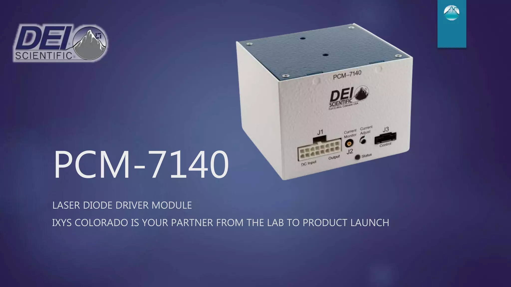
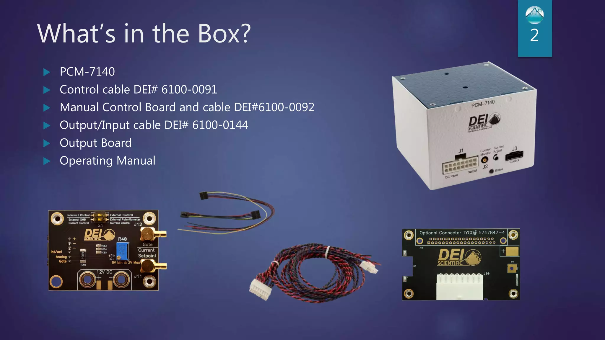

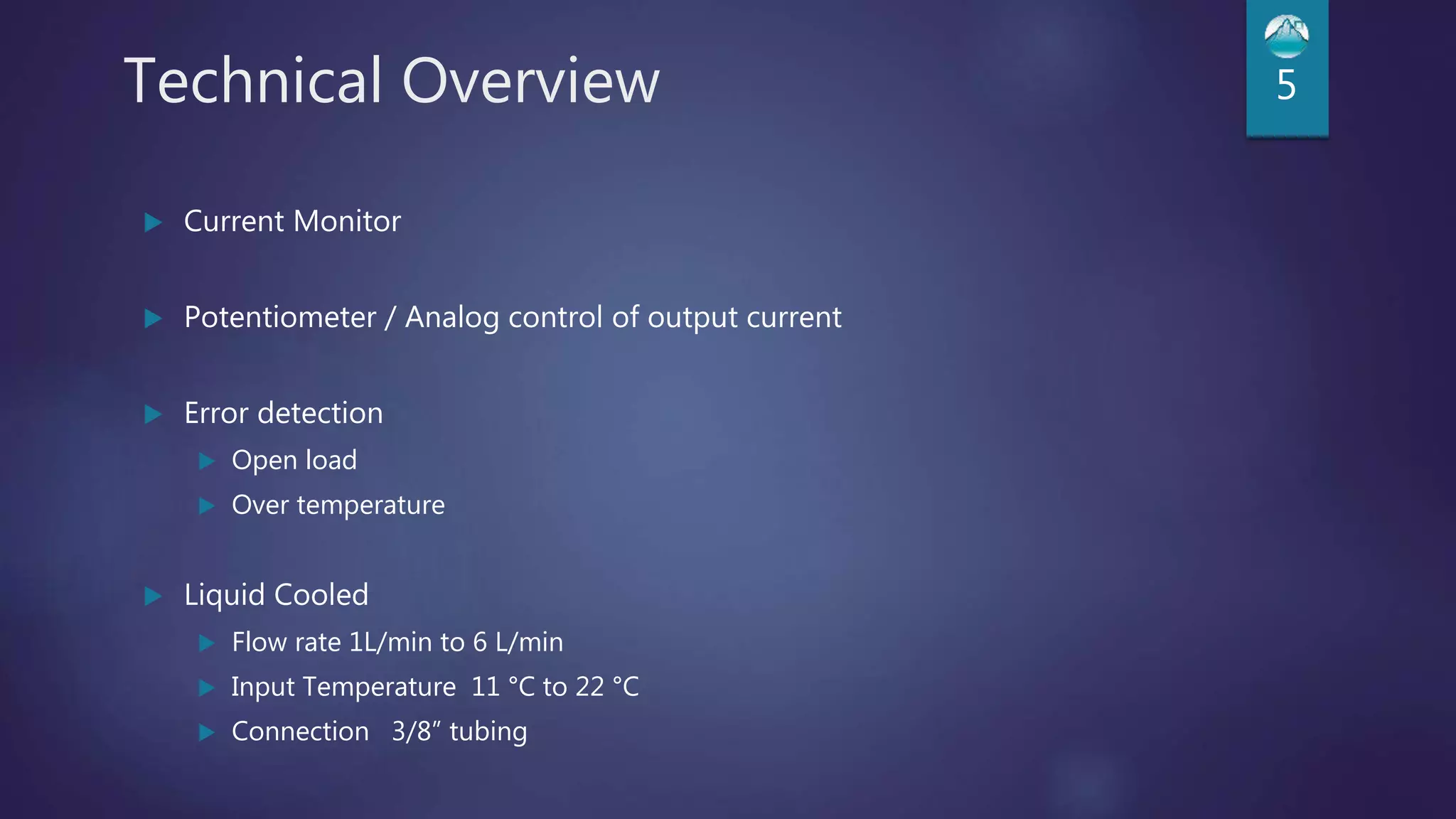
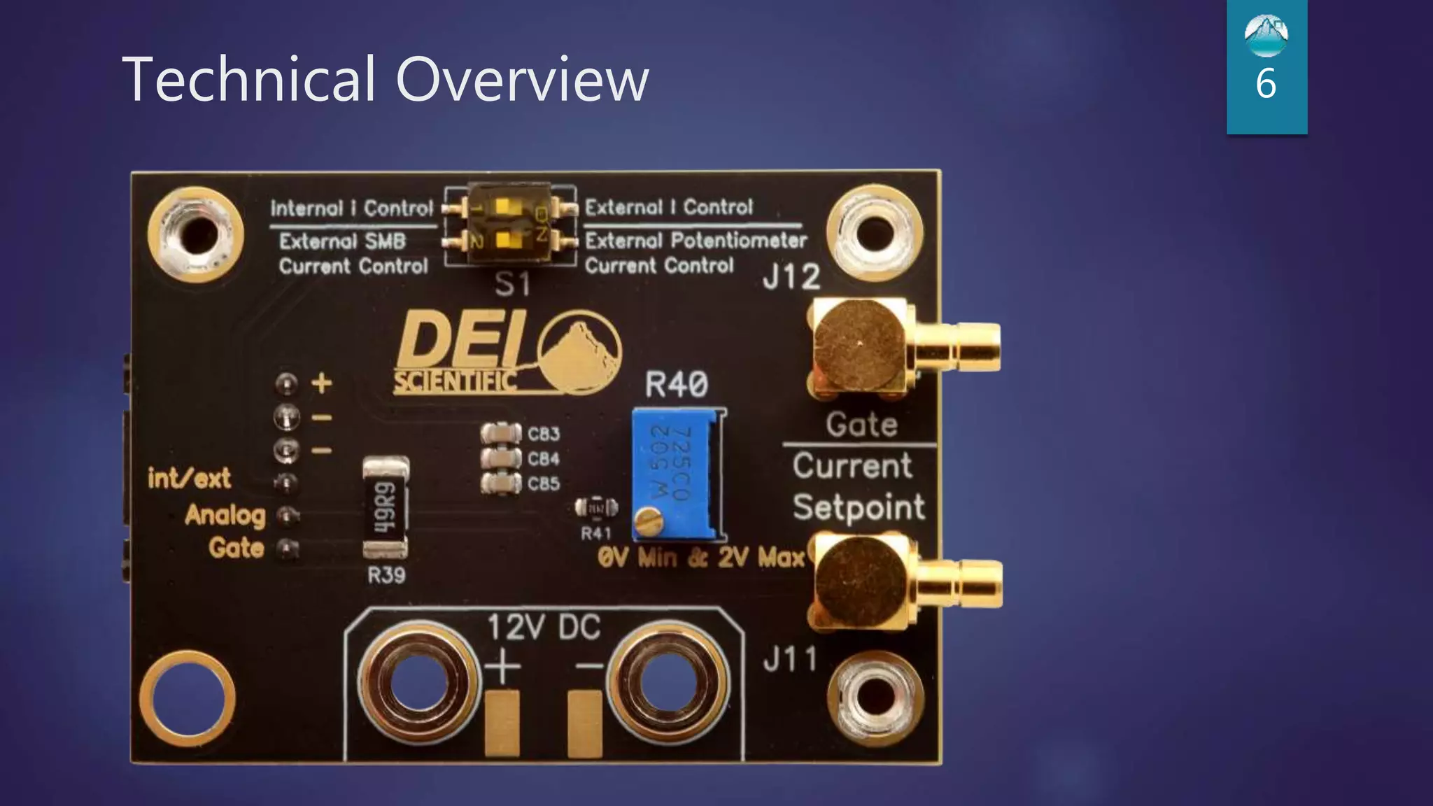
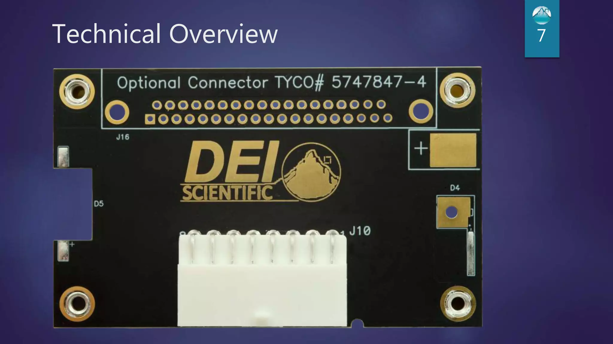
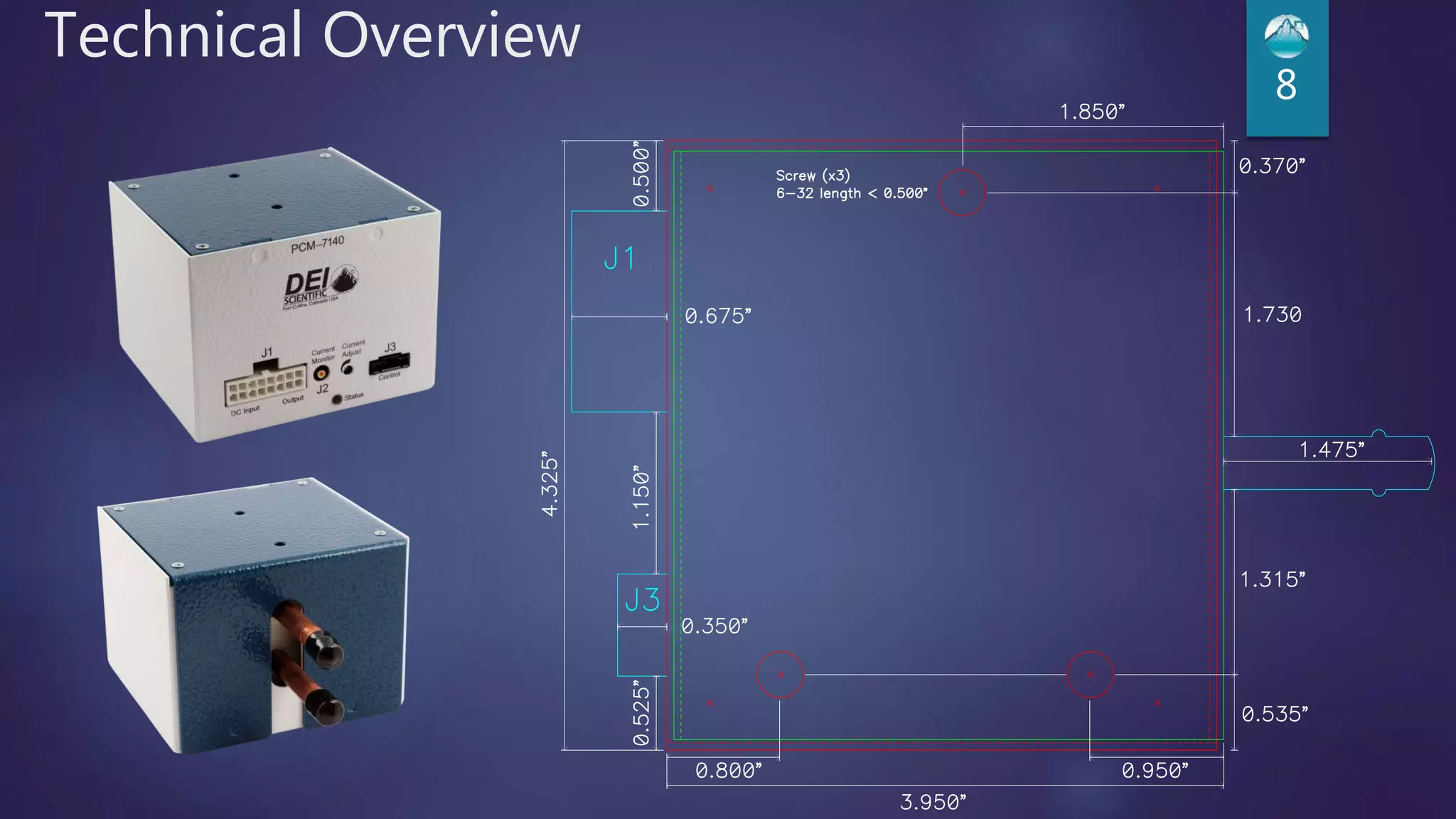
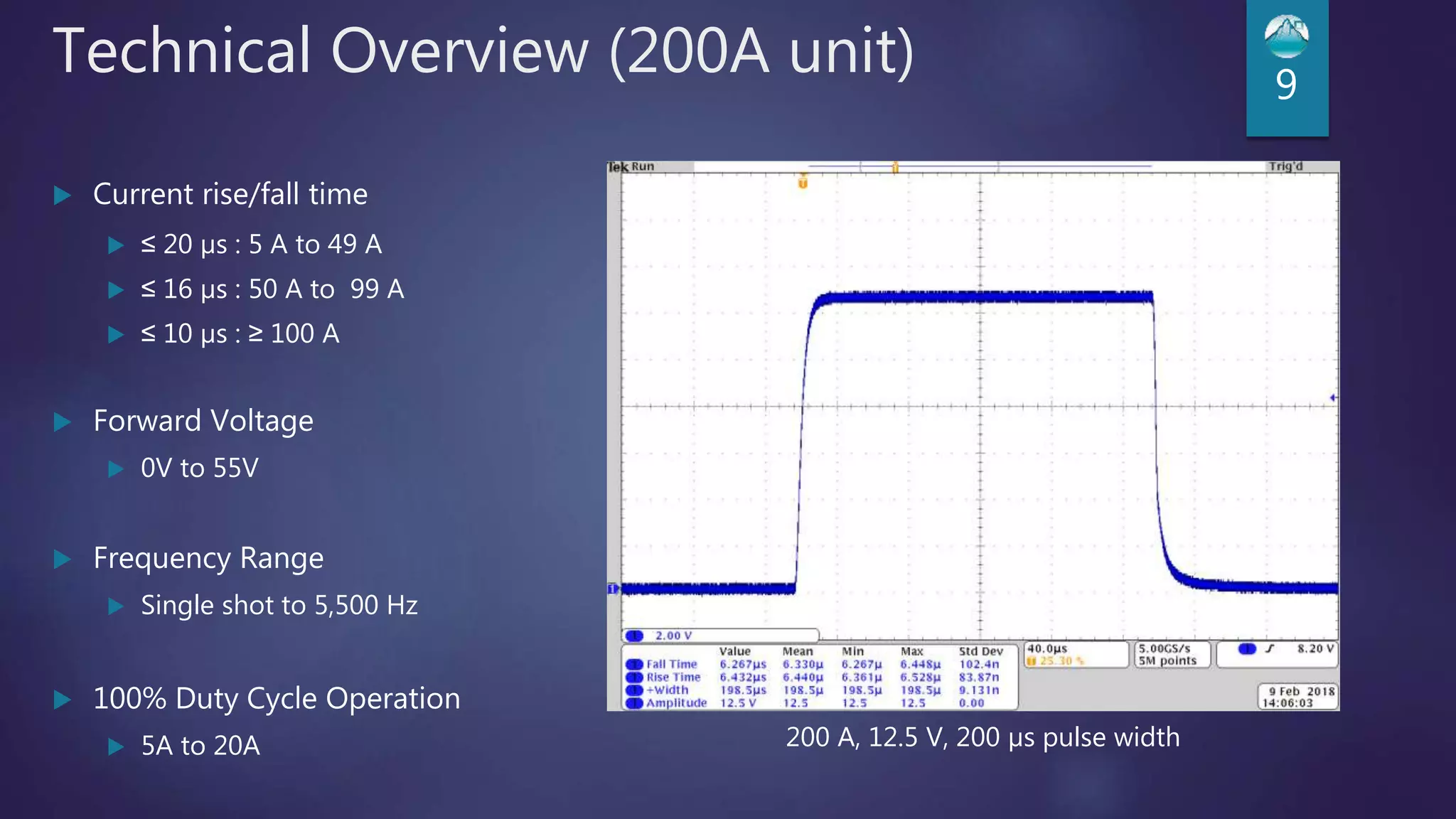
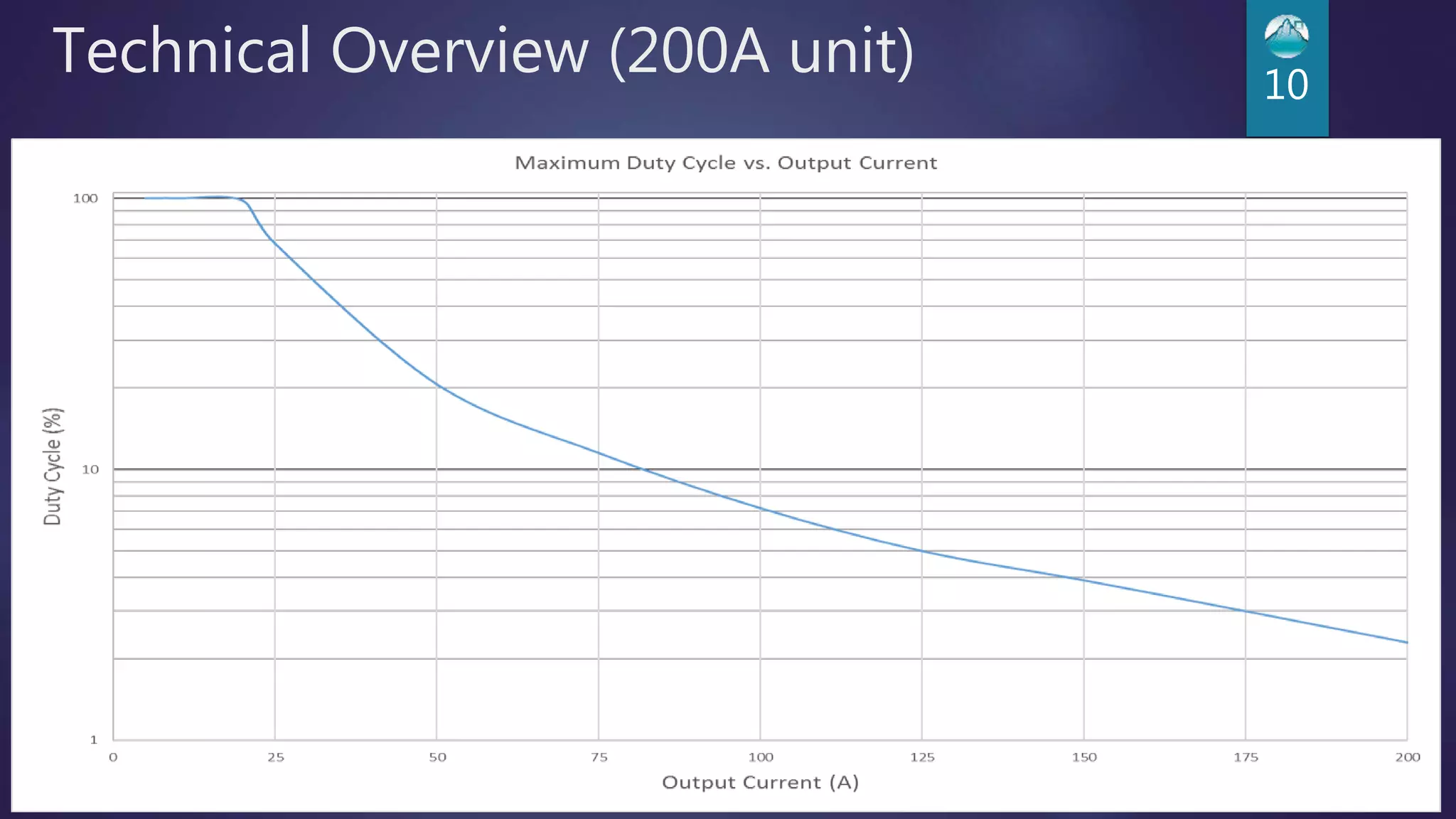
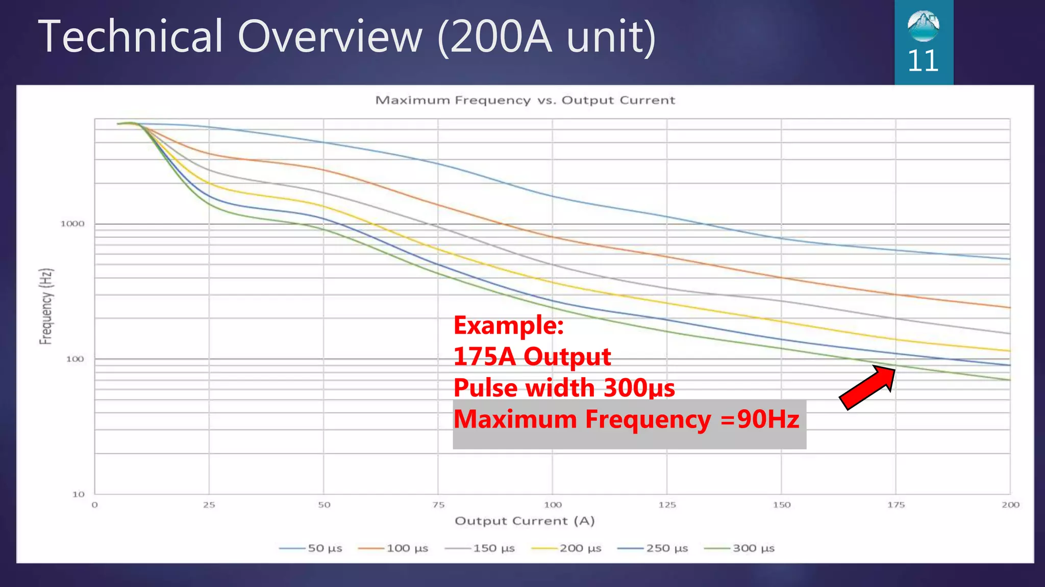
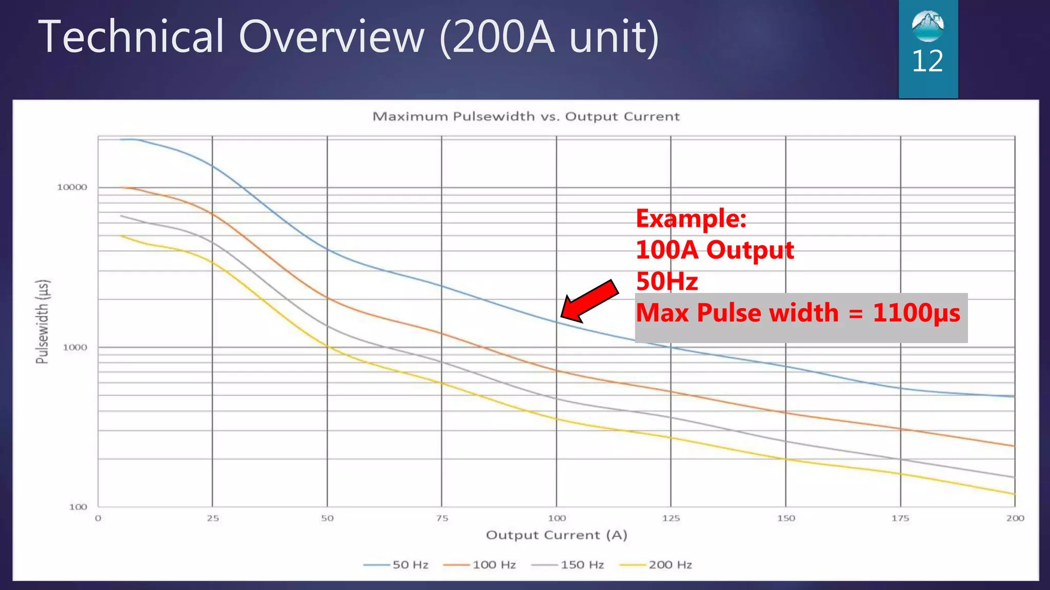
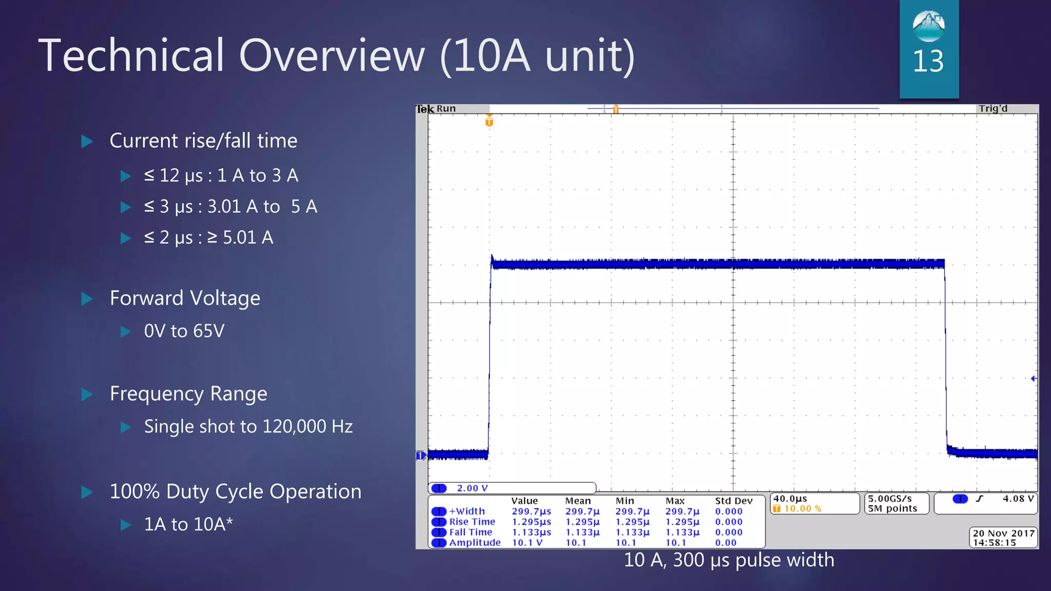

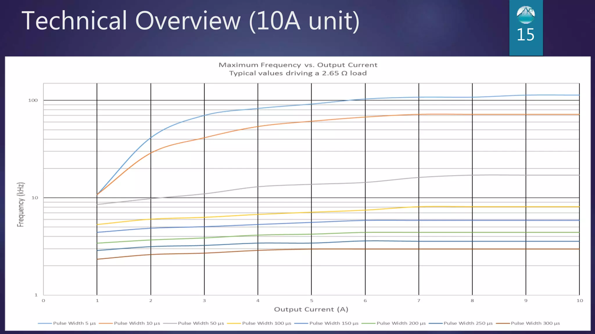
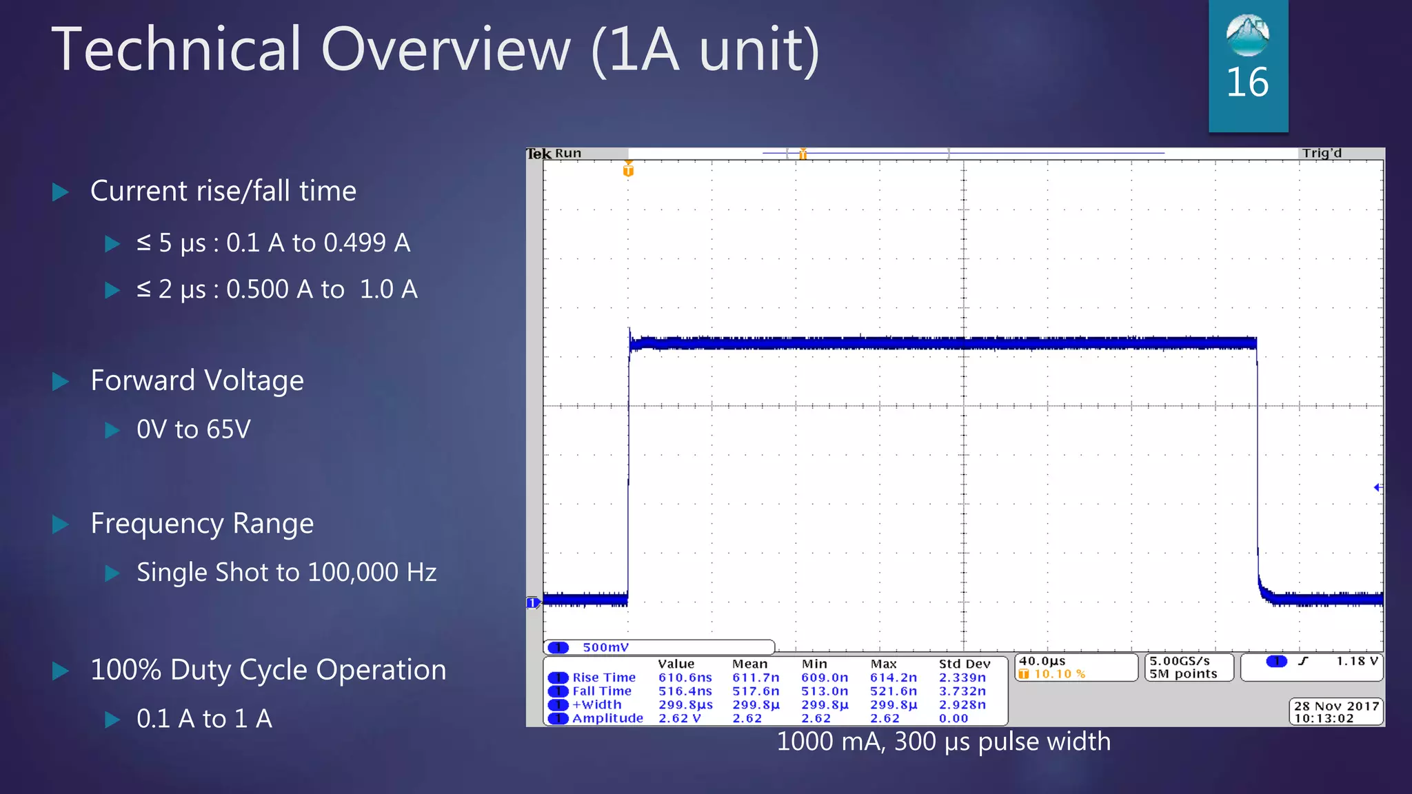
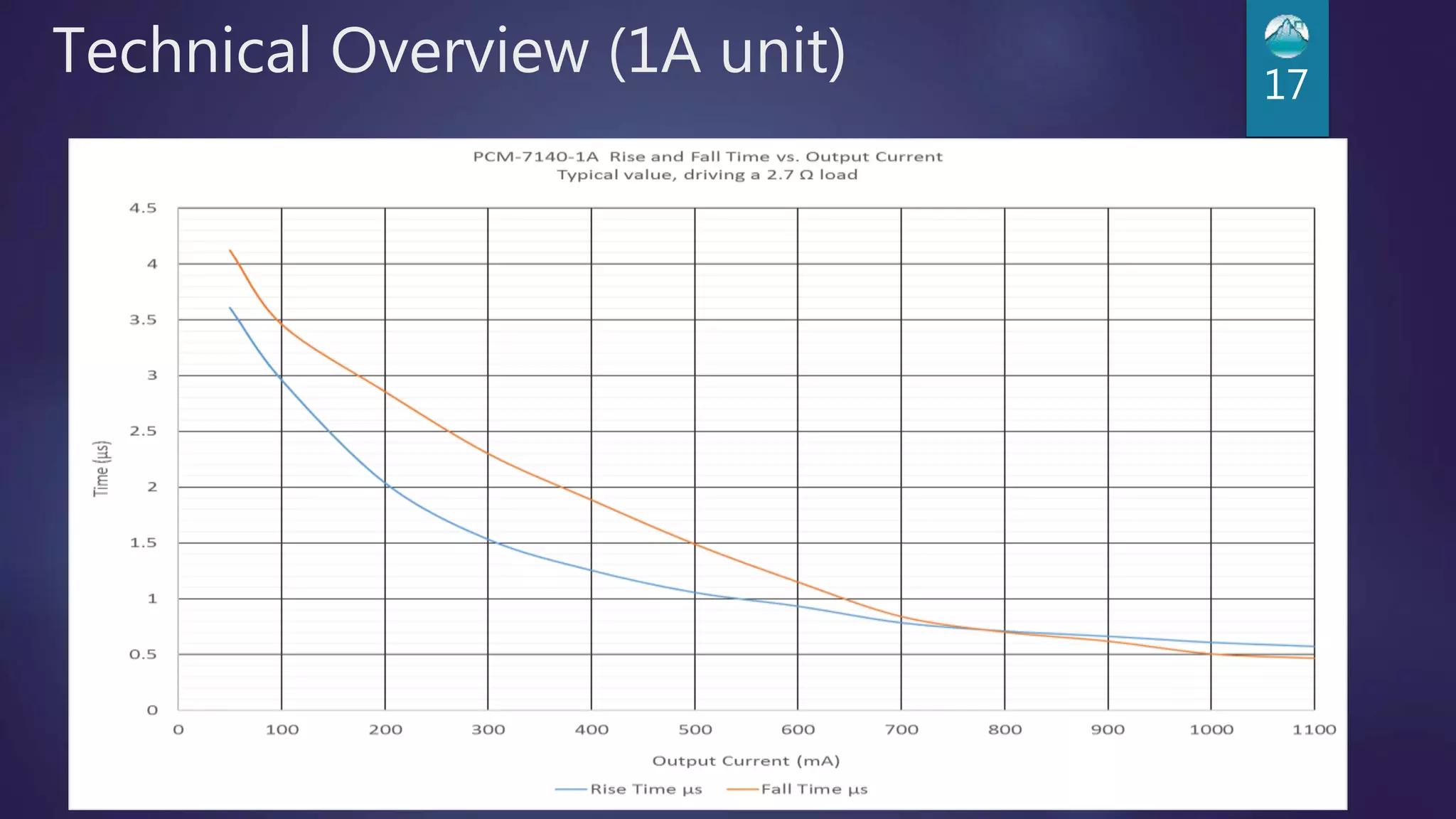
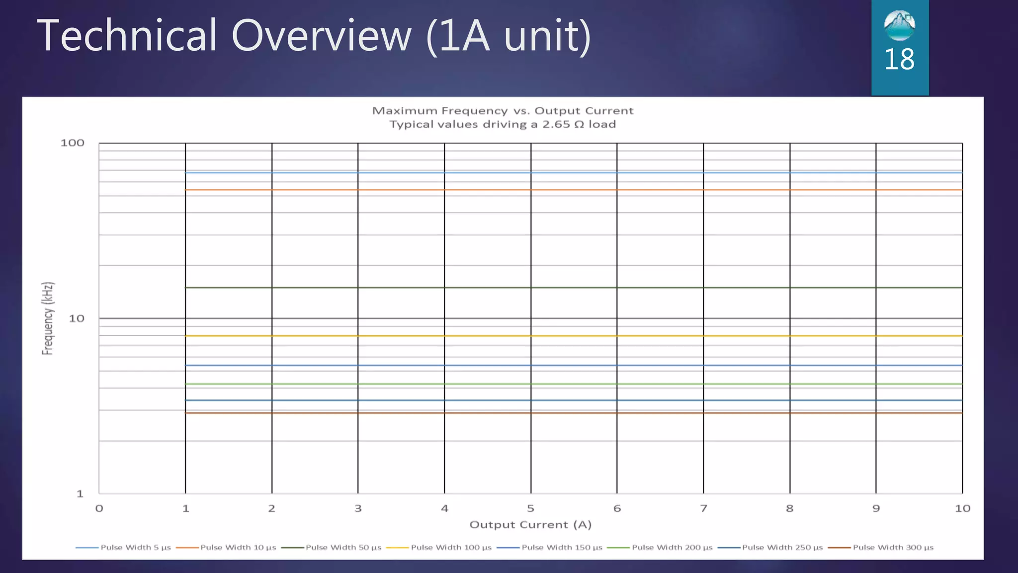
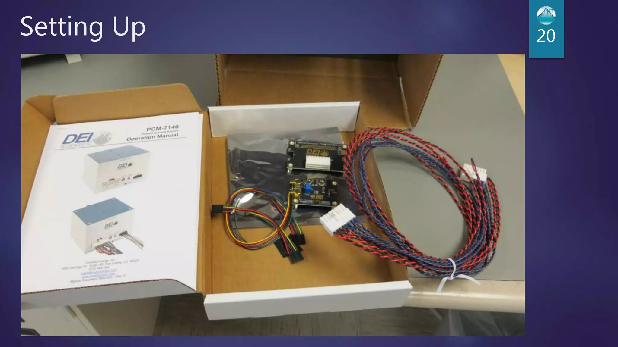
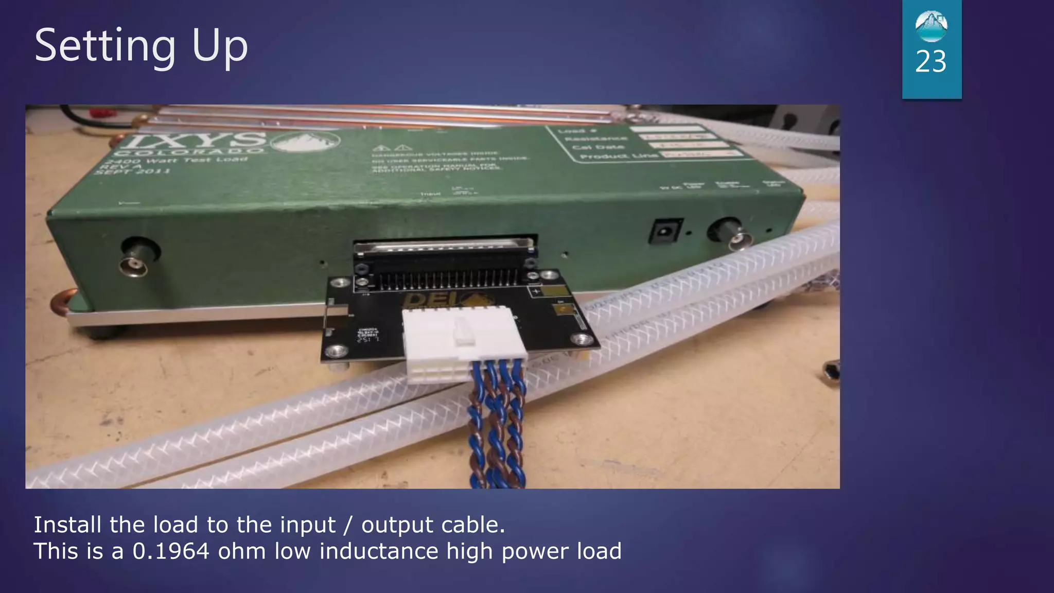
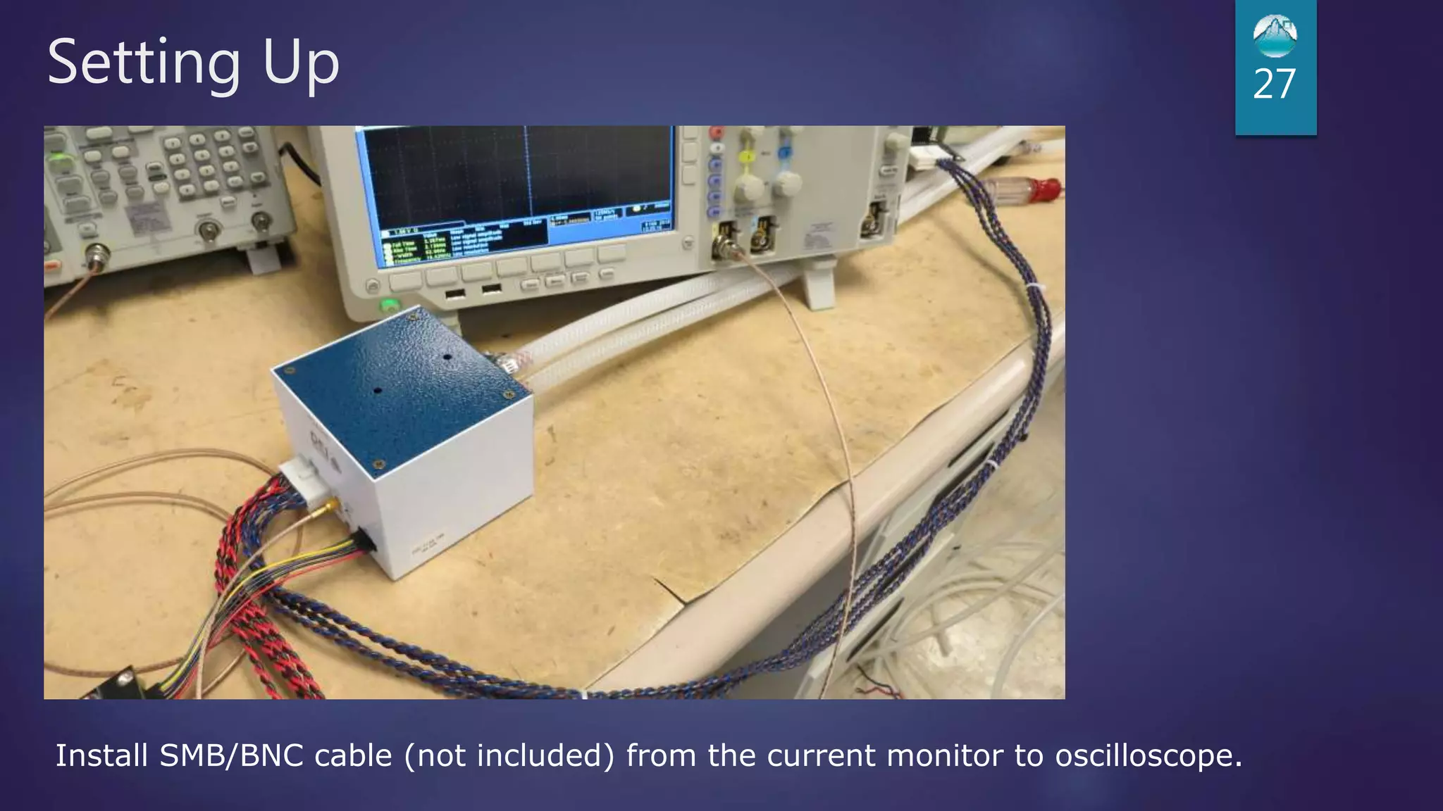
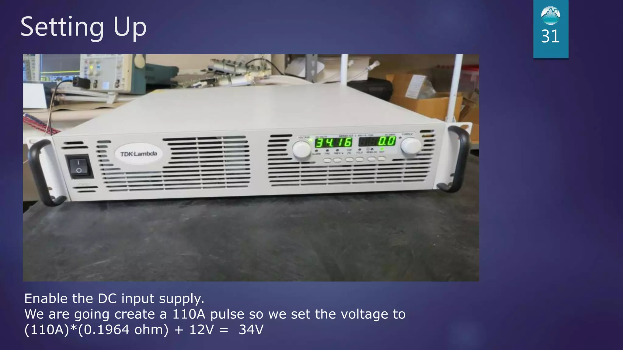
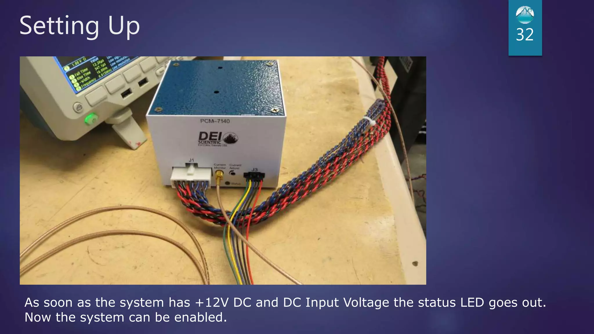
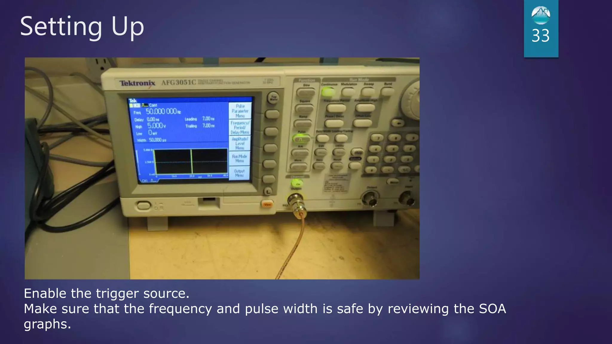
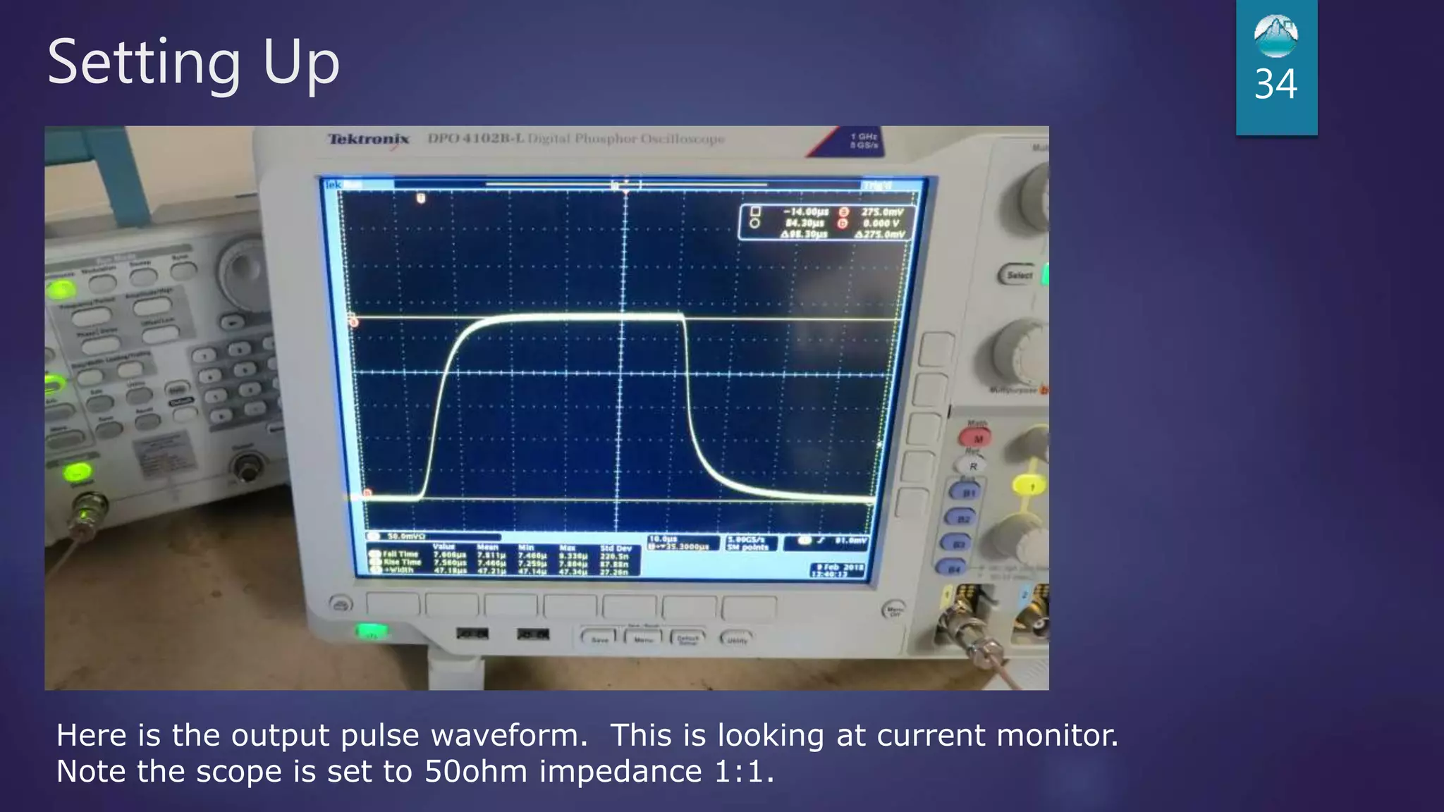
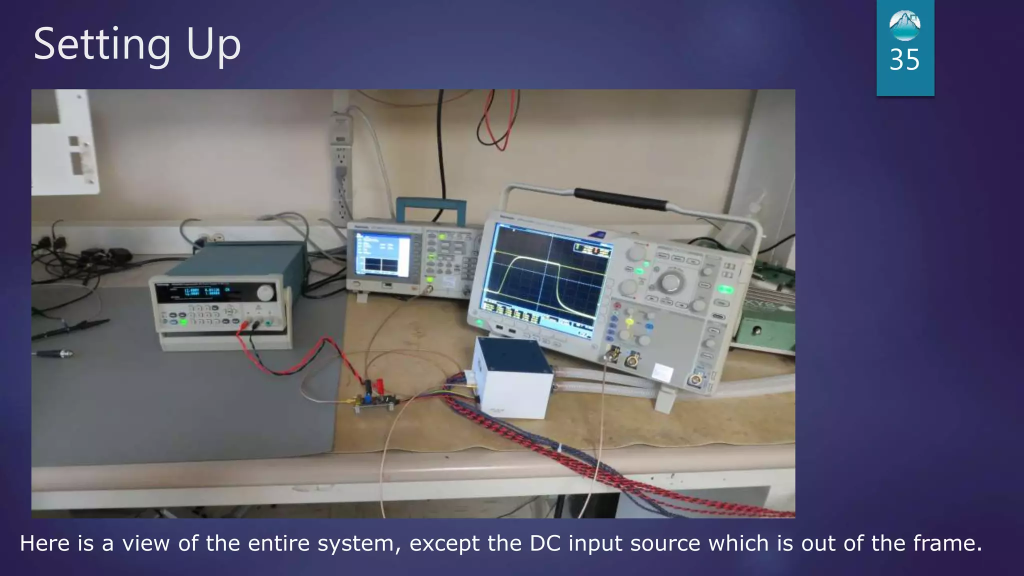

The pcm-7140 laser diode driver module by IXYS Colorado includes a control cable, manual, and various output boards for different current ranges (0.1a to 200a) with fast rise and fall times. It features a liquid cooling system, error detection for open load and over-temperature conditions, and is designed for high frequency and duty cycle operations. The document outlines setup instructions, troubleshooting steps, and example scenarios for effective operation.


![Coded Agents – with UiPath SDK + LangGraph [Virtual Hands-on Workshop]](https://cdn.slidesharecdn.com/ss_thumbnails/codedagentsdeck-251215155422-5497c599-thumbnail.jpg?width=640&height=640&fit=bounds)


