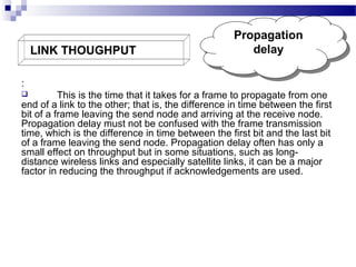
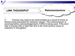
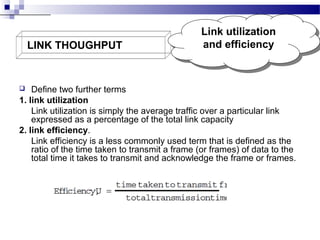
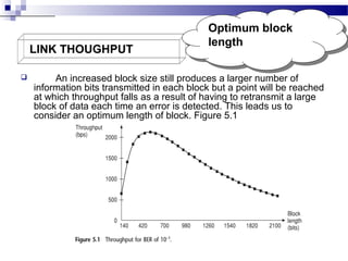
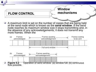
3. LINK THOUGHPUT
Frame
Frame
overheads
overheads
The major factors that cause throughput to be less than the
transmission rate are listed below as follows:
Frame overheads
Propagation delay
Acknowledgements
Retransmissions
Processing time
Link utilization and efficiency
Effect of errors on throughput
Effect of ARQ on throughput
Optimum block length
4. LINK THOUGHPUT
Frame
Frame
overheads
overheads
:
Not all of the contents of a frame are information bits. Typically,
in addition to information bits, a frame also contains a header and a
trailer. The header contains control information such as an address
and sequence numbers. The trailer normally contains error-checking
bits which are often called a frame check sequence. A frame might
typically contain 256 bytes of which 251 are information bits, thus
leading to a 2% reduction in potential throughput even before the frame
is transmitted.
5. LINK THOUGHPUT
Propagation
Propagation
delay
delay
:
This is the time that it takes for a frame to propagate from one
end of a link to the other; that is, the difference in time between the first
bit of a frame leaving the send node and arriving at the receive node.
Propagation delay must not be confused with the frame transmission
time, which is the difference in time between the first bit and the last bit
of a frame leaving the send node. Propagation delay often has only a
small effect on throughput but in some situations, such as longdistance wireless links and especially satellite links, it can be a major
factor in reducing the throughput if acknowledgements are used.
6. LINK THOUGHPUT
Acknowledgemen
Acknowledgemen
ts
ts
:
Normally, some form of ARQ is used and time may be spent
waiting for acknowledgements to reach the send node, particularly if
there is a half duplex link. Since the acknowledgements will normally
be much shorter than the information frames, the transmission time of
the acknowledgements can often be ignored. However, the propagation
delay of an acknowledgement will be the same as that of an
information frame providing they take the same transmission path.
7. LINK THOUGHPUT
Retransmissions
Retransmissions
:
Frames may need to be retransmitted as a result of errors or
frames being discarded for whatever reason. The retransmission is
accompanied by acknowledgements if ARQ is being used. If the error
rate or discard rate is high then this is the most serious cause of
reduction in throughput.
8. LINK THOUGHPUT
Processing time
Processing time
:
Time is spent at the send and receive nodes in processing the
data. This includes detecting (and possibly correcting) errors and also
the implementation of flow control. If wireless links are used there will
be further processing delays associated with the modulation and
demodulation process.
9. LINK THOUGHPUT
Link utilization
Link utilization
and efficiency
and efficiency
Define two further terms
1. link utilization
Link utilization is simply the average traffic over a particular link
expressed as a percentage of the total link capacity
2. link efficiency.
Link efficiency is a less commonly used term that is defined as the
ratio of the time taken to transmit a frame (or frames) of data to the
total time it takes to transmit and acknowledge the frame or frames.
10. LINK THOUGHPUT
Link utilization
Link utilization
and efficiency
and efficiency
Link efficiency will depend on the type of ARQ used. The
efficiency of a link with stop-and-wait ARQ can be determined as
follows. If the time taken to transmit a frame or block of data is tf, the
propagation delay for both frame and acknowledgement is td, the
time taken to transmit an acknowledgement is ta and the total
processing time is tp, then:
In many situations the acknowledgement transmission time and
processing times can be ignored, giving:
11. LINK THOUGHPUT
Effect of errors on
Effect of errors on
throughput
throughput
The effect of transmission impairments on a data
communications link is to introduce errors . The number of errors
present in a link is expressed as a BER. If a link has a BER of 0.000
001 (10−6), this means that there is a probability of 0.000 001 that
any bit is in error. Alternatively, we can say that, on average, one in
every 1 000 000 bits will be in error. This may seem a very low error
rate but if bits are transmitted as a block in a frame then the
probability of the frame being in error will be much greater. The
frame error rate, P, can be obtained from the bit error rate, E, as
follows. The probability of a bit being error free is 1 − E and the
probability of a block of length n being error free is (1 − E)n. The
frame error probability is therefore:
12. LINK THOUGHPUT
Effect of ARQ on
Effect of ARQ on
throughput
throughput
:
If a frame is transmitted m times then the probability of this
occurring is the probability of transmitting m − 1 consecutive
erroneous frames followed by a single correctly received frame. This
is given by:
A problem which arises is that the number of times, m, that a frame
is transmitted will vary according to some form of probability
distribution. Since the determination of the value of m is not
particularly simple, the value is just presented here without any
analysis. For a full analysis see Bertsekas and Gallager (1992). If
stop-and-wait ARQ is used then the average number of times that a
frame is transmitted is given by:
13. LINK THOUGHPUT
1.
2.
3.
Effect of ARQ on
Effect of ARQ on
throughput
throughput
If go-back-n ARQ is used then an error detected in a frame causes
that frame, along with all other unacknowledged frames, to be retransmitted.
Frames are retransmitted only when a frame is rejected at the receiver for
being erroneous. In practice, there may be other reasons for frames being
retransmitted.
The rejection of frame i by the receiver is followed by the transmitter sending
frames i + 1, i + 2, . . . , i + n − 1 and then retransmitting the original frame i.
This may not always be the case since there may be fewer than n − 1
frames waiting to be transmitted after frame I .
The resulting analysis, which is also carried out in Bertsekas and Gallager
(1992), gives the number of times that a frame is likely to be transmitted as:
14. LINK THOUGHPUT
Optimum block
Optimum block
length
length
An increased block size still produces a larger number of
information bits transmitted in each block but a point will be reached
at which throughput falls as a result of having to retransmit a large
block of data each time an error is detected. This leads us to
consider an optimum length of block. Figure 5.1
15. FLOW CONTROL
Window
Window
mechanisms
mechanisms
A maximum limit is set on the number of copies that are being held
at the send node which is known as the send window. If the send
node reaches its maximum window size it stops transmitting and, in
the absence of any acknowledgements, it does not transmit any
more frames. When the
Figure 5.2
Operation of send window: (a) window full; (b) continuous
flow possible.
16. FLOW CONTROL
Effect of windows
Effect of windows
on throughput
on throughput
The throughput of a frame-oriented link using stop-andwait ARQ
depends upon the number of information bits, k, the frame
transmission time, tf, and the propagation delay, td, according to the
expression:
17. LINK MANAGEMENT
This process seems almost trivial at first sight but the situation becomes more
complex if a failure occurs on a link or at a node. A problem arises when frames have
been accepted for transmission over a link but have not reached a receive node before
a failure occurs. Link management procedures need to be able to cope with such
failures.
Figure 5.4
Link set-up and disconnection.
18. HIGH–LEVEL DATA LINK CONTROL (HDLC) PROTOCOL
The protocol allows for a variety of different types of link, the two
nodes at either end of the link being referred to as stations. To satisfy
the requirements of different types of link the protocol distinguishes
between three modes of operation (although only two of them are
normally used) and two types of link configuration:
1.Unbalanced
configuration:
2.Balanced configuration:
19. HIGH–LEVEL DATA LINK CONTROL (HDLC) PROTOCOL
Unbalanced
Unbalanced
configuration
configuration
This is the situation in which a single primary station has
control over the operation of one or more secondary stations. Frames
transmitted by the primary are called commands and those by the
secondary responses. A typical example of this type of configuration is
a multidrop link in which a single computer is connected to a number
of DTEs which are under its control. This mode of working is called
normal response mode ( NRM).
20. HIGH–LEVEL DATA LINK CONTROL (HDLC) PROTOCOL
Balanced
Balanced
configuration
configuration
This refers to a point-to-point link in which the nodes at each
end of the link have equal status, each capable of issuing a command.
HDLC calls these combined stations and they can transmit both
commands and responses. This mode of working is called
asynchronous balanced mode ( ABM ).
21. HIGH–LEVEL DATA LINK CONTROL (HDLC) PROTOCOL
HDLC frame structure
HDLC uses synchronous transmission with data being
transmitted in frames. All frames have the common format shown in
Figure 5.5. The address and control fields are known collectively as a
header and the error-checking bits are called the frame check
sequence (FCS) or trailer.
22. .
POINT-TO POINT PROTOCOL
PPP frame
PPP frame
structure.
structure.
The frame header contains 1-byte address and control fields along with
an additional 2-byte protocol field. PPP does not assign individual station
addresses and the address field contains the binary sequence 11111111.
The control field contains the binary sequence 00000011. The protocol field
contains 2 bytes that identify the protocol encapsulated in the information
field of the frame. In addition to IP, PPP supports other protocols, including
Novell’s Internetwork Packet Exchange ( IPX) and IBM’s Synchronous
Network Architecture (SNA). The FCS performs an identical function to that
in an HDLC frame.
Figure 5.10
PPP frame structure.
23. .
POINT-TO POINT PROTOCOL
PPP uses a Link Control Protocol ( LCP) to establish, configure
and test the data link connection that goes through four distinct
phases: Three classes of LCP frames exist. Link-establishment
frames are used to establish and configure a link; link-termination
frames are used to terminate a link; and link maintenance frames
are used to manage and debug a link.