1. THE TRANSPORT LAYER
The Transport Layer: The Transport Service, Elements of Transport Protocols, Congestion
Control,The internet transport protocols: UDP, TCP, Performance problems in computer
networks, Networkperformance measurement.
THE TRANSPORT SERVICE
Services Provided to the Upper Layers
The ultimate goal of the transport layer is to provide efficient, reliable, and cost-effective data
transmission service to its users, normally processes in the application layer. To achieve this, the
transport layer makes use of the services provided by the network layer. The software and/or
hardware within the transport layer that does the work is called the transport entity. The transport
entity can be located in the operating system kernel, in a library package bound into network
applications, in a separate user process, or even on the network interface card. The first two options
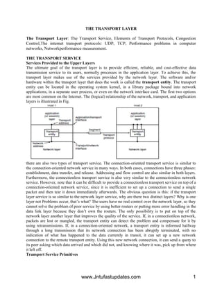
are most common on the Internet. The (logical) relationship of the network, transport, and application
layers is illustrated in Fig.
there are also two types of transport service. The connection-oriented transport service is similar to
the connection-oriented network service in many ways. In both cases, connections have three phases:
establishment, data transfer, and release. Addressing and flow control are also similar in both layers.
Furthermore, the connectionless transport service is also very similar to the connectionless network
service. However, note that it can be difficult to provide a connectionless transport service on top of a
connection-oriented network service, since it is inefficient to set up a connection to send a single
packet and then tear it down immediately afterwards. The obvious question is this: if the transport
layer service is so similar to the network layer service, why are there two distinct layers? Why is one
layer not Problems occur, that’s what? The users have no real control over the network layer, so they
cannot solve the problem of poor service by using better routers or putting more error handling in the
data link layer because they don’t own the routers. The only possibility is to put on top of the
network layer another layer that improves the quality of the service. If, in a connectionless network,
packets are lost or mangled, the transport entity can detect the problem and compensate for it by
using retransmissions. If, in a connection-oriented network, a transport entity is informed halfway
through a long transmission that its network connection has been abruptly terminated, with no
indication of what has happened to the data currently in transit, it can set up a new network
connection to the remote transport entity. Using this new network connection, it can send a query to
its peer asking which data arrived and which did not, and knowing where it was, pick up from where
it left off.
Transport Service Primitives
www.Jntufastupdates.com 1
2. To allow users to access the transport service, the transport layer must provide some operations to
application programs, that is, a transport service interface. Each transport service has its own
interface. In this section, we will first examine a simple (hypothetical) transport service and its
interface to see the bare essentials. In the following section, we will look at a real example. The
transport service is similar to the network service, but there are also some important differences. The
main difference is that the network service is intended to model the service offered by real networks,
warts and all. Real networks can lose packets, so the network service is generally unreliable.
A
quick note on terminology is now in order. For lack of a better term, we will use the term segment
for messages sent from transport entity to transport entity.TCP, UDP and other Internet protocols use
this term. Some older protocols used the ungainly name TPDU (Transport Protocol Data Unit).
That term is not used much anymore now but you may see it in older papers and books the network
entity similarly processes the packet header and then passes the contents of the packet payload up to
the transport entity. This nesting is illustrated in Fig. 6-3
Connection Establishment
Establishing a connection sounds easy, but it is actually surprisingly tricky. At first glance, it would
seem sufficient for one transport entity to just send a CONNECTION REQUEST segment to the
destination and wait for a CONNECTION ACCEPTED reply. The problem occurs when the network
can lose, delay, corrupt, and duplicate packets. This behaviour causes serious complications. Imagine
a network that is so congested that acknowledgements hardly ever get back in time and each packet
times out and is retransmitted two or three times. Suppose that the network uses datagrams inside and
that every packet follows a different route. Some of the packets might get stuck in a traffic jam inside
the network and take a long time to arrive. That is, they may be delayed in the network and pop out
much later, when the sender thought that they had been lost. The worst possible nightmare is as
follows. A user establishes a connection with a bank, sends messages telling the bank to transfer a
large amount of money to the account of a not-entirely-trustworthy person. Unfortunately, the
packets decide to take the scenic route to the destination and go off exploring a remote corner of the
network. The sender then times out and sends them all again. This time the packets take the shortest
route and are delivered quickly so the sender releases the connection.
Packet lifetime can be restricted to a known maximum using one (or more) of the following
techniques:
1. Restricted network design.
www.Jntufastupdates.com 2
3. 2. Putting a hop counter in each packet.
3. Time stamping each packet.
The first technique includes any method that prevents packets from looping, combined with some
way of bounding delay including congestion over the (now known) longest possible path. It is
difficult, given that internets may range from a single city to international in scope. The second
method consists of having the hop count initialized to some appropriate value and decremented each
time the packet is forwarded. The network protocol simply discards any packet whose hop counter
becomes zero. The third method requires each packet to bear the time it was created, with the routers
agreeing to discard any packet older than some agreed-upon time. This latter method requires the
router clocks to be synchronized, which itself is a nontrivial task, and in practice a hop counter is a
close enough approximation to age.
TCP uses this three-way handshake to establish connections. Within a connection, a timestamp is
used to extend the 32-bit sequence number so that it will not wrap within the maximum packet
lifetime, even for gigabit-per-second connections. This mechanism is a fix to TCP that was needed as
it was used on faster and faster links. It is described in RFC 1323 and called PAWS (Protection
Against Wrapped Sequence numbers). Across connections, for the initial sequence numbers and
before PAWS can come into play, TCP originally use the clock-based scheme just described.
However, this turned out to have security vulnerability. The clock made it easy for an attacker to
predict the next initial sequence number and send packets that tricked the three-way handshake and
established a forged connection. To close this hole, pseudorandom initial sequence numbers are used
for connections in practice.
the
initial sequence numbers not repeat for an interval even though they appear random to an observer.
Otherwise, delayed duplicates can wreak havoc.
Connection Release
Releasing a connection is easier than establishing one. Nevertheless, there are more pitfalls than one
might expect here. As we mentioned earlier, there are two styles of terminating a connection:
asymmetric release and symmetric release Asymmetric release is the way the telephone system
works: when one party hangs up, the connection is broken. Symmetric release treats the connection
as two separate unidirectional connections and requires each one to be released separately.
www.Jntufastupdates.com 3
4. Asymmetric release is abrupt and may result in data loss. Consider the scenario of Fig. After the
connection is established, host 1 sends a segment that arrives properly at host 2. Then host 1 sends
another segment. Unfortunately, host 2 issues a DISCONNECT before the second segment arrives.
The result is that the connection is released and data are lost.
Crash Recovery
If hosts and routers are subject to crashes or connections are long-lived (e.g., large software or media
downloads) recovery from these crashes becomes an issue. If the transport entity is entirely within
the hosts, recovery from network
and router crashes is straightforward. The transport entities expect lost segments all the time and
know how to cope with them by using retransmissions. A more troublesome problem is how to
recover from host crashes. In particular, it may be desirable for clients to be able to continue working
when servers crash and quickly reboot. To illustrate the difficulty, let us assume that one host, the
client, is sending a long file to another host, the file server, using a simple Stop-and-wait protocol.
The transport layer on the server just passes the incoming segments to the transport user, one by one.
Partway through the transmission, the server crashes. When it comes back up, its tables are
reinitialized, so it no longer knows precisely where it was. In an attempt to recover its previous
status, the server might send a broadcast segment to all other hosts, announcing that it has just
crashed and requesting that its clients inform it of the status of all open connections. Each client can
be in one of two states: one segment outstanding, S1, or no segments outstanding, S0. Based on only
this state information, the client must decide whether to retransmit the most recent segment.
UDP Protocol
UDP provides connectionless, unreliable, datagram service. Connectionless service means that there
is no logical connection between the two ends exchanging messages. Each message is an independent
entity encapsulated in a datagram.
www.Jntufastupdates.com 4
5. UDP does not see any relation (connection) between consequent datagram coming from the same
source and going to the same destination.
UDP has an advantage: it is message-oriented. It gives boundaries to the messages exchanged. An
application program may be designed to use UDP if it is sending small messages and the simplicity
and speed is more important for the application than reliability.
User Datagram
UDP packets, called user datagram, have a fixed-size header of 8 bytes made of four fields, each of 2
bytes (16 bits).
. The 16 bits can define a total length of 0 to 65,535 bytes. However, the total length needs to be less
because a UDP user datagram is stored in an IP datagram with the total length of 65,535 bytes. The
last field can carry the optional checksum
UDP Services
Process-to-Process Communication
UDP provides process-to-process communication using socket addresses, a combination of IP
addresses and port numbers.
Connectionless Services
As mentioned previously, UDP provides a connection less service. This means that each user
datagram sent by UDP is an independent datagram. There is no relationship between the different
user data grams even if they are coming from the same source process and going to the same
destination program.
Flow Control
UDP is a very simple protocol. There is no flow control, and hence no window mechanism. The
receiver may overflow with incoming messages.
Error Control
There is no error control mechanism in UDP except for the checksum. This means that the sender
does not know if a message has been lost or duplicated.
Checksum
UDP checksum calculation includes three sections: a pseudo header, the UDP header, and the data
coming from the application layer. The pseudo header is the part of the header of the IP packet in
www.Jntufastupdates.com 5
6. which the user datagram is to be encapsulated with some fields filled with 0s
UDP Applications
UDP Features
Connectionless Service
As we mentioned previously,
UDP is a connectionless protocol. Each UDP packet is independent from other packets sent by
the same application program. This feature can be considered as an advantage or disadvanta8e
depending on the application requirements.
UDP does not provide error control; it provides an unreliable service. Most applications expect
reliable service from a transport-layer protocol. Although a reliable service is desirable.
Typical Applications
The following shows some typical applications that can benefit more from the services of UDP
UDP is suitable for a process that requires simple request-response communication with little
concern for flow and error control
UDP is suitable for a process with internal flow- and error-control mechanisms. For example, the
Trivial File Transfer Protocol (TFIP)
UDP is a suitable transport protocol for multicasting. Multicasting capability is embedded in the
UDP software
UDP is used for management processes such as SNMP
UDP is used for some route updating protocols such as Routing Information Protocol (RIP)
UDP is normally used for interactive real-time applications that cannot tolerate uneven delay
between sections of a received message
TRANSMISSION CONTROL PROTOCOL
Transmission Control Protocol (TCP) is a connection-oriented, reliable protocol. TCP explicitly
defines connection establishment, data transfer, and connection teardown phases to provide a
connection-oriented service.
TCP Services
Process-to-Process Communication
As with UDP, TCP provides process-to-process communication using port numbers. We have
already given some of the port numbers used by TCP.
Stream Delivery Service
In UDP, a process sends messages with predefined boundaries to UDP for delivery. UDP adds its
own header to each of these messages and delivers it to IP for transmission.
TCP, on the other hand, allows the sending process to deliver data as a stream of bytes and allows the
receiving process to obtain data as a stream of bytes.
www.Jntufastupdates.com 6
7. TCP creates an environment in which the two processes seem to be connected by an imaginary
"tube" that carries their bytes across the Internet.
www.Jntufastupdates.com 7
8. Sending and Receiving Buffers
Because the sending and the receiving processes may not necessarily write or read data at the same
rate, TCP needs buffers for storage.
There are two buffers, the sending buffer and the receiving buffer, one for each direction.
At the sender, the buffer has three types of chambers. The white section contains empty
chambers that can be filled by the sending process (producer).
The colored area holds bytes that have been sent but not yet acknowledged.
The TCP sender keeps these bytes in the buffer until it receives an acknowledgment. The shaded
area contains bytes to be sent by the sending TCP.
The operation of the buffer at the receiver is simpler. The circular buffer is divided into two
areas (shown as white and colored).
The white area contains empty chambers to be filled by bytes received from the network.
The colored sections contain received bytes that can be read by the receiving process. When a
byte is read by the receiving process, the chamber is recycled and added to the pool of empty
chambers.
Segments
Although buffering handles the disparity between the speed of the producing and consuming
Processes, we need one more step before we can send data.
The network layer, as a service provider for TCP, needs to send data in packets, not as a stream
of bytes. At the transport layer, TCP groups a number of bytes together into a packet called a
segment.
The segments are encapsulated in an IP datagram and transmitted. This entire operation is
transparent to the receiving process.
Format
The segment consists of a header of 20 to 60 bytes, followed by data from the application
program.The header is 20 bytes if there are no options and up to 60 bytes if it contains options.
www.Jntufastupdates.com 8
9. Source port address This is a 16-bit field that defines the port number of the application program in
the host that is sending the segment.
Destination port address This is a 16-bit field that defines the port number of the application
program in the host that is receiving the segment.
Sequence number This 32-bit field defines the number assigned to the first byte of data contained in
this segment.
Acknowledgment number This 32-bit field defines the byte number that the receiver of the segment
is expecting to receive from the other party.
Header length This 4-bit field indicates the number of 4-byte words in the TCP header. The length
of the header can be between 20 and 60 bytes.
A TCP Connection
TCP is connection-oriented. a connection-oriented transport protocol establishes a logical path
between the source and destination.
All of the segments belonging to a message are then sent over this logical path.
TCP operates at a higher level. TCP uses the services of IP to deliver individual segments to the
receiver, but it controls the connection itself.
In TCP, connection-oriented transmission requires three phases: connection establishment, data
transfer, and connection termination.
www.Jntufastupdates.com 9
10. Connection Establishment
TCP transmits data in full-duplex mode. When two TCPs in two machines are connected, they are
able to send segments to each other simultaneously.
Three- Way Handshaking
The connection establishment in TCP is called three-way handshaking. an application program,
called the client, wants to make a connection with another application program, called the server,
www.Jntufastupdates.com 10
11. using TCP as the transport-layer protocol The process starts with the server. The server program tells
its TCP that it is ready to accept a connection. This request is called a passive open.
Although the server TCP is ready to accept a connection from any machine in the world, it cannot
make the connection itself.
The client program issues a request for an active open. A client that wishes to connect
to an open server tells its TCP to connect to a particular server.
A SYN segment cannot carry data, but it consumes one sequence number.
A SYN + ACK segment cannot carry data, but it does consume one sequence number.
An ACK segment, if carrying no data, consumes no sequence number.
www.Jntufastupdates.com 11
13. COMPUTER NETWORKS –
APPLICATION LAYER
DOMAIN NAME SYSTEM
This is primarily used for mapping host and e-mail destinations to IP addresses but can also be used
other purposes. DNS is defined in RFCs 1034 and 1035.
Working:-
To map a name onto an IP address, an application program calls a library procedure called Resolver,
passing it the name as a parameter.
The resolver sends a UDP packet to a local DNS server, which then looks up the name and returns the IP
address to the resolver, which then returns it to the caller.
Armed with the IP address, the program can then establish a TCP connection with the destination, or
send it UDP packets.
1.
2.
3.
The DNS name space.
Resource Records.
Name Servers.
1. THE DNS NAME SPACE:
The Internet is divided into several hundred top level domains, where each domain covers many hosts.
Each domain is partitioned into sub domains, and these are further partitioned as so on. All these domains can
be represented by a tree, in which the leaves represent domains that have no sub domains. A leaf domain may
contain a single host, or it may represent a company and contains thousands of hosts. Each domain is named by
the path upward from it to the root. The components are separated by periods (pronounced “dot”)
Eg: Sun Microsystems Engg. Department = eng.sun.com.
The top domain comes in 2 flavours:-
Generic: com(commercial), edu(educational instructions), mil(the U.S armed forces, government), int
(certain international organizations), net( network providers), org (non profit organizations).
Page 1
www.Jntufastupdates.com 13
14. COMPUTER NETWORKS –
Country: include 1 entry for every country. Domain names can be either absolute (ends with a period
e.g. eng.sum.com) or relative (doesn’t end with a period). Domain names are case sensitive and the
component names can be up to 63 characters long and full path names must not exceed 255 characters.
Insertions of a domain into the tree can be done in 2 days:-
• Under a generic domain ( Eg: cs.yale.edu)
• Under the domain of their country (E.g: cs.yale.ct.us)
2. RESOURCE RECORDS:
Every domain can have a sent of resource records associated with it. For a single host, the most common
resource record is just its IP address. When a resolver gives a domain name to DNS, it gets both the resource
records associated with that name i.e., the real function of DNS is to map domain names into resource records.
A resource record is a 5-tuple and its format is as follows:
Domain Name Time to live Type Class Value
Domain _name : Tells the domain to which this record applies.
Time- to- live : Gives an identification of how stable the record is (High Stable = 86400 i.e. no. of seconds
/day) ( High Volatile = 1 min)
Type: Tells what kind of record this is.
Class: It is IN for the internet information and codes for non internet information
Value: This field can be a number a domain name or an ASCII string
Page 2
www.Jntufastupdates.com 14
15. 2.
COMPUTER NETWORKS –
3. NAME SERVERS:
It contains the entire database and responds to all queries about it. DNS name space is divided up into non-
overlapping zones, in which each zone contains some part of the tree and also contains name servers holding the
authoritative information about that zone.
When a resolver has a query about a domain name, it passes the query to one of the local name servers:
1. If the domain being sought falls under the jurisdiction of name server, it returns the authoritative resource
records (that comes from the authority that manages the record,and is always correct).
If the domain is remote and no information about the requested domain is available locally the name server
sends a query message to the top level name server for the domain requested.
E.g.: A resolver of flits.cs.vle.nl wants to know the IP address of the host Linda.cs.yale.edu
Page 3
www.Jntufastupdates.com 15
16. COMPUTER NETWORKS –
Step 1: Resolver sends a query containing domain name sought the type and the class to local name server,
cs.vu.nl.
Step 2: Suppose local name server knows nothing about it, it asks few others nearby name servers. If none of
them know, it sends a UDP packet to the server for edu-server.net.
Step 3: This server knows nothing about Linda.cs.yale.edu or cs.yale.edu and so it forwards the request to the
name server for yale.edu.
Step 4: This one forwards the request to cs.yale.edu which must have authoritative resource records.
Step 5 to 8: The resource record requested works its way back in steps 5-8 This query method is known as
Recursive Query
3. When a query cannot be satisfied locally, the query fails but the name of the next server along the line to try
is returned.
ELECTRONIC MAIL
1. ARCHITECTURE AND SERVICES:
E-mail systems consist of two subsystems. They are:-
(1). User Agents, which allow people to read and send e-mail
(2). Message Transfer Agents, which move messages from source to destination
E-mail systems support 5 basic functions:-
a. Composition
b. Transfer
c. Reporting
d. Displaying
e. Disposition
(a). Composition: It refers to the process of creating messages and answers. Any text editor is used for body of
the message. While the system itself can provide assistance with addressing and numerous header fields
attached to each message.
(b). Reporting: It has to do with telling the originator what happened to the message that is, whether it was
delivered, rejected (or) lost.
(c). Transfer: It refers to moving messages from originator to the recipient.
(d). Displaying: Incoming messages are to be displayed so that people can read their email.
(e). Disposition: It concerns what the recipient dose with the message after receiving it. Possibilities include
throwing it away before reading (or) after reading, saving it and so on.
Most systems allow users to create mailboxes to store incoming e-mail. Commands are needed to create and
destroy mailboxes, inspect the contents of mailboxes, insert and delete messages from mailboxes, and so on.
Page 4
www.Jntufastupdates.com 16
17. COMPUTER NETWORKS –
(1) THE USER AGENT
A user agent is normally a program (sometimes called a mail reader) that accepts a variety of commands for
composing, receiving, and replying to messages, as well as for manipulating mailboxes.
SENDING E-MAIL
To send an e-mail message, a user must provide the message, the destination address, and possibly some
other parameters. The message can be produced with a free-standing text editor, a word processing program, or
possibly with a specialized text editor built into the user agent. The destination address must be in a format that
the user agent can deal with. Many user agents expect addresses of the form .
READING E-MAIL
When a user agent is started up, it looks at the user's mailbox for incoming e-mail before displaying
anything on the screen. Then it may announce the number of messages in the mailbox or display a one-line
summary of each one and wait for a command.
Page 5
www.Jntufastupdates.com 17
18. COMPUTER NETWORKS –
(2) MESSAGE FORMATS
RFC 822
Messages consist of a primitive envelope (described in RFC 821), some number of header fields, a blank line,
and then the message body. Each header field (logically) consists of a single line of ASCII text containing the
field name, a colon, and, for most fields, a value.
MIME The Multipurpose Internet Mail Extensions
RFC 822 specified the headers but left the content entirely up to the users. Nowadays, on the worldwide
Internet, this approach is no longer adequate. The problems include sending and receiving
1. Messages in languages with accents (e.g., French and German).
2. Messages in non-Latin alphabets (e.g., Hebrew and Russian).
3. Messages in languages without alphabets (e.g., Chinese and Japanese).
4. Messages not containing text at all (e.g., audio or images).
A solution was proposed in RFC 1341 called MIME (Multipurpose Internet Mail Extensions)
The basic idea of MIME is to continue to use the RFC 822 format, but to add structure to the message
body and define encoding rules for non-ASCII messages. By not deviating from RFC 822, MIME messages can
be sent using the existing mail programs and protocols. All that has to be changed are the sending and receiving
programs, which users can do for themselves.
Page 6
www.Jntufastupdates.com 18
19. COMPUTER NETWORKS –
MESSAGE TRANSFER
The message transfer system is concerned with relaying messages from the originator to the recipient.
The simplest way to do this is to establish a transport connection from the source machine to the destination
machine and then just transfer the message.
SMTP THE SIMPLE MAIL TRANSFER PROTOCOL
SMTP is a simple ASCII protocol. After establishing the TCP connection to port 25, the sending
machine, operating as the client, waits for the receiving machine, operating as the server, to talk first. The server
starts by sending a line of text giving its identity and telling whether it is prepared to receive mail. If it is not,
the client releases the connection and tries again later.
Even though the SMTP protocol is completely well defined, a few problems can still arise.
One problem relates to message length. Some older implementations cannot handle messages
exceeding 64 KB.
Another problem relates to timeouts. If the client and server have different timeouts, one of them may
give up while the other is still busy, unexpectedly terminating the connection.
Finally, in rare situations, infinite mailstorms can be triggered.
For example, if host 1 holds mailing list and host 2 holds mailing list and each list contains an entry
for the other one, then a message sent to either list could generate a never-ending amount of e-mail traffic unless
somebody checks for it.
FINAL DELIVERY
With the advent of people who access the Internet by calling their ISP over a modem, it breaks down.
One solution is to have a message transfer agent on an ISP machine accept e-mail for its customers and store it
in their mailboxes on an ISP machine. Since this agent can be on-line all the time, e-mail can be sent to it 24
hours a day.
Page 7
www.Jntufastupdates.com 19
20. COMPUTER NETWORKS –
POP3
POP3 begins when the user starts the mail reader. The mail reader calls up the ISP (unless there is already a
connection) and establishes a TCP connection with the message transfer agent at port 110. Once the connection
has been established, the POP3 protocol goes through three states in sequence:
1. Authorization.
2. Transactions.
3. Update.
The authorization state deals with having the user log in.
The transaction state deals with the user collecting the e-mails and marking them for deletion from the mailbox.
The update state actually causes the e-mails to be deleted.
www.Jntufastupdates.com 20