1. MOTOROLA SYSTEM SYMPOSIUM 1999
GENERAL BUSINESS INFORMATION
SS7 Link Utilization Formulas to Improve
Network Management and Network Availability
Elliot M. Stewart
Department BC555
Cellular Infrastructure Group/Network Solutions Sector
IL27/3227-AR
QA3176@email.mot.com
ABSTRACT
The Motorola GSM BSS cellular network utilizes SS7 links to communicate with the MSC. Traditional network
monitoring of SS7 link utilization by customers has relied on protocol analyzer equipment, which has several drawbacks.
By defining SS7 link utilization formulas and accessing SS7 link statistics data from the Motorola network equipment, link
utilization data can be calculated and presented to the customer in a direct manner. This approach improves the ability to
better manage SS7 link utilization and avoid outage-inducing overloads. The result is better 5-NINES performance in
both the availability and ease of use of 5-NINES metrics.
1. Introduction
Cellular operators today have the daunting task of
building and profitably maintaining complex mobile
networks. Typical activities of the cellular operator
include network component installation and
commissioning, operation and maintenance (O&M),
radio frequency planning, capacity planning, and fault
management analysis of network problems. A
paramount goal of such activities is to help ensure
network availability with high levels of quality for the
mobile user.
To achieve a cellular network with high availability,
not only must the individual network components have
high availability, but also the communication links that
connect each component. Communication links are
typically provisioned based upon predicted network
traffic levels. However, such factors as accelerated
network growth and severe peak traffic usage can stress
link provisioning estimates. Consequently, over-
utilization of communication links may occur that result
in outages.
2. Background
The GSM digital cellular network system is comprised
of various network components and communication
links. The Motorola GSM Base Station System (BSS) is
comprised of a Base Site Controller (BSC) and one or
more Base Transceiver Stations (BTS). The BSS
network connects to a Mobile Switching Center (MSC)
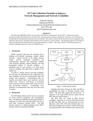
through a Remote Transcoder (RXCDR).
MTL link(s)
BSS
mobiles
Figure 1: GSM network entities
Signaling information between the MSC and BSS is
accomplished by means of Message Transfer Links
(MTL). The MTL links employ the SS7 protocol. A
depiction of the major GSM network entities and the
MTL links are found in Figure 1.
The MTL links are crucial to BSS network
availability. If there are no in service MTL links between
the BSS and MSC, then no call processing can occur.
Operators collect MTL (SS7) link utilization data via a
link protocol analyzer in an effort to monitor link usage.
By monitoring MTL (SS7) utilization data, operators can
MSCPSTN
RXCDR
BSC
BTS BTS
OMC
2. better manage MTL links and avoid outage inducing
overloads. However, link analyzer data collection
procedures are expensive; i.e., time-consuming, labor
intensive, and requires specialized equipment.
3. Overview
This paper details an alternative approach to using a
hardware protocol analyzer in providing MTL (SS7) link
utilization data. This new approach relies on collecting
SS7 link statistics within the BSS network and
combining that raw data into formulas at the Operations
and Maintenance Center (OMC) to provide a measure of
MTL (SS7) link utilization. Thus, the utilization data are
gathered via statistical means from the network without
specialized equipment required.
The remainder of this paper is outlined as follows:
The derivation of the MTL (SS7) link
utilization formulas is documented.
The data collection and presentation of
the MTL (SS7) link utilization
formulas is covered.
The benefits of using formulas over the
hardware protocol analyzer are
enumerated.
4. Derivation of Formulas
At the Motorola GSM BSC site, software processes
implement the Message Transfer Part (MTP) Layer 2 and
Layer 3 of the SS7 protocol, as defined in reference [1],
to support the MTL (SS7) link communication with the
MSC. Internal to the software processes, MTL (SS7)
link statistics are kept in accordance with reference [2].
The goal in the derivation of the link utilization formulas
from statistics is to account for all the traffic being sent
or received on a link for a particular period in order to
calculate a utilization level. Link utilization defined in its
simplest terms as a percentage is:
%100
(sec))
sec
(
time
bytes
ratetransfer
bytes
Equation 1: Link utilization
To account for all traffic on a link, the software
processes must track all bytes transmitted and received,
which are formatted into signaling units. There are three
different SS7 signaling unit formats defined: message
signal units (MSU), link status signal units (LSSU), and
fill-in signal units (FISU). FISUs serve as filler, when no
data or link status messages appear on the link, and thus
are not a contributor to the link utilization calculation.
However, MSUs and LSSUs do contribute to the total
amount of data transmitted or received on a particular
link and need to be counted.
The format of an MSU is shown in Figure 2. Below
each field name is the size of that field in bits, where
eight bits equal one byte or octet.
Flag
CK
SIF
SIO
LI
FIB
FSN
BIB
BSN
Flag
8 16 8n n>=2 8 2 6 1 7 1 7 8
Figure 2: basic format of an MSU [1]
The format of an LSSU is shown in Figure 3. Below
each field name is the size of that field in bits.
Flag
CK
SF
LI
FIB
FSN
BIB
BSN
Flag
8 16 8/16 2 6 1 7 1 7 8
Figure 3: basic format of an LSSU [1]
For the formats shown in Figure 2 and Figure 3, the
fields are defined as:
Flag signaling unit (SU) delimiter
CK check bits
SIF signaling information field
SIO service information octet
LI length indicator
FIB forward indicator bit
FSN forward sequence number
BIB backward indicator bit
BSN backward sequence number
SF status field
At the Motorola GSM BSC statistics are kept, as
defined in reference [2], to count all MSUs, including the
fixed overhead and variable SIF/SIO data part, and
LSSUs. Statistical counts are kept for both the transmit
and receive direction. Additionally, the time the MTL
link is in the in service state is monitored.
Separate statistic counts are maintained for each
individual MTL (SS7) link. A summary of each statistic
and the scope of what it monitors are shown in Table 1.
Note that an octet is another name for a byte-sized field.
3. Statistic Name Definition
mtp_sif_sio_tx Indicates the number of MSU SIF and
SIO octets transmitted over a signaling
link.
mtp_sif_sio_rx Indicates the number of MSU SIF and
SIO octets received over a signaling
link.
mtp_msu_tx Indicates the number of MSUs
transmitted over a signaling link.
mtp_msu_rx Indicates the number of MSUs
received over a signaling link.
sib_tx Indicates the number of status
indication busy (SIB) LSSUs
transmitted over a signaling link.
sib_rx Indicates the number of SIB LSSUs
received over a signaling link.
mtp_link_ins Indicates the duration of time in
milliseconds that a particular signaling
link is in the in service state.
Table 1: MTL (SS7) statistic definitions.
With the statistic definitions and the basic framing of
link utilization in Equation 1, one can finally construct a
formula for MTL (SS7) link utilization. Substituting
generic SS7 related fields into Equation 1 one gets:
In GSM, MTL links exist on E1/T1 spans where the
data transfer rate is 64kbps. In addition, the following
two assumptions are made when defining the MTL (SS7)
link utilization formulas:
1. The opening flag for each SU is the
closing flag of the previous SU [1]
(section 2.3.2)
2. LSSUs use an SF length of 1 (SIB = 1
byte) instead of 2
Using those assumptions, and referring to Figure 2 and
Figure 3, LSSUs will be seven bytes in length. MSUs,
excluding the SIF and SIO part, will be six bytes in
length. Thusly, the formula for MTL (SS7) link
utilization in the transmit direction becomes:
After simplifying terms, the formula then becomes:
Equation 2: MTL (SS7) Link Utilization (TX)
The formula for the receive direction is defined in a
similar manner.
Equation 3: MTL (SS7) Link Utilization (RX)
Note that the formulas are defined from the perspective
of the BSS. So, the transmit (TX) formula provides a
measure of link utilization from the BSS to MSC
direction. The receive (RX) formula provides a measure
of link utilization from the MSC to BSS direction.
There is one drawback to the link utilization formulas.
The statistics defined for the SS7 link are updated in the
higher protocol layers. The SS7 protocol is a framing
protocol and uses bit stuffing to avoid the flag pattern
(01111110) from appearing internal to the rest of the
frame or SU [3]. Any extra bits stuffed into an SU by
the sender are removed by the receiver in the lower
layers. Thus the extra bits are transparent to the upper
protocol layers and are not accounted for in the statistics.
The result is that the formula calculations will likely
show a slightly lower link utilization then actually
experienced, as any stuffed bits increase the utilization of
the link.
The inaccuracy of the link utilization formulas due to
bit stuffing is also a factor for the link protocol analyzers.
Typical link analyzers just provide a total count of bytes
transmitted and received with some giving an additional
breakdown based upon SU type. Thus, the link analyzer
suffers from the same inaccuracy as the link formulas, as
bit stuffing is not accounted in the metrics provided by
the analyzer.
5. Data Collection and Presentation
The Motorola GSM BSS maintains and demarcates
statistic data on an interval basis. Intervals can range
from 5 to 60 minutes in duration, though are typically set
to 30 or 60 minutes in the field. When an interval
expires, statistic values for the past interval are saved
locally at the BSS, and statistic values are reset to zero
to begin updating for the next interval. The procedure of
data generation on an interval basis is done for all
statistics and continues indefinitely.
At the completion of each interval, a transaction
timeserviceinlinktransferdatalink
LSSUsMSUs
%100
__sec1000sec8
sec
64000
7____6__
inslinkmtpmbitsbytebits
bytestxsibtxsiosifmtptxmsumtp
%100
__8
7____6__
inslinkmtp
txsibtxsiosifmtptxmsumtp
%100
__8
7____6__
inslinkmtp
rxsibrxsiosifmtprxmsumtp
4. between the BSS and OMC takes place. The BSS
uploads statistic data for the expired interval to the OMC
for storage in a performance management database
(PMdb). The PMdb allows the retrieval of statistical
data by a reporting mechanism. In addition, the PMdb
can act as a long-term storage, allowing the ability to do
trend analysis on the data.
At the OMC, cellular operators can run reports on
individual statistics or sets of statistics. The OMC has
the ability to combine individual statistics into formulas,
such as the MTL (SS7) link utilization transmit and
receive formulas. Data for each individual MTL (SS7)
link in the network can be observed for stored statistic
intervals within the PMdb. All links can be observed
individually or in groups as well as tabular vs. graphical
presentation. The OMC allows operators to actively
monitor MTL (SS7) link utilization in both transmit and
receive direction.
6. Benefits of Formulas Over Protocol Analyzer
As mentioned previously, the link utilization formulas
shown in Equation 2 and Equation 3 provide an
alternative means to the hardware protocol analyzer for
monitoring the performance of the MTL (SS7) links.
There are several advantages to using the formulas in
place of the hardware protocol analyzer. Those
advantages are enumerated here.
Data Capture
A typical hardware protocol analyzer, such as the
Siemens K1103, can only monitor up to eight MTL
(SS7) links located on four physical spans at one time.
The limitation on the simultaneous number of links an
analyzer can monitor means that an operator can only
obtain data from one or two BSS per analyzer. With
cellular networks typically containing 50 to 100 BSSs
with two to five MTLs per BSS, the analyzer limitation
is severe. The only option to the operator in obtaining
MTL (SS7) link utilization data network-wide is to
purchase multiple analyzers, which is costly, or to visit
each BSS with an analyzer for a short period in a round-
robin fashion.
Conversely, the statistical approach overcomes the
limitation of the analyzer. All the cellular operator has to
do to obtain MTL (SS7) link utilization for the entire
network is to enable the SS7 statistics at each BSS. This
task is accomplished via standard O&M commands
issued from the OMC and can be done once at system
startup or at any time. Statistical data for each MTL
(SS7) link will be generated and sent to the OMC in the
procedure outlined in section 5.
Data Timeframe
Purchasing enough analyzers to monitor all MTL
(SS7) links is impractical, both in terms of the hardware
cost and the personnel required to run the equipment.
As a result, operators use the round-robin method of
obtaining MTL (SS7) link utilization data. By visiting
each BSS separately and collecting data with the
analyzer, the operator is only obtaining a brief snap shot
of utilization. Data will be available for a set of MTL
(SS7) links, but only for the period when the analyzer
was in place. A consequence is that an MTL (SS7) link
may show acceptable levels of utilization at time of
measurement, but may become over-utilized before the
next measurement is done. If such a situation occurred,
an MTL outage may result, adversely affecting system
availability.
On the other hand, obtaining MTL (SS7) link
utilization by means of statistics allows continuous
monitoring. The data captured and presented at the
OMC is continuously gathered from each BSS. With the
PMdb, long term trending and comparison of MTL
(SS7) link performance is possible. The likelihood of
having an MTL (SS7) link become over-utilized without
detection is reduced or eliminated. Thus, the level of
system availability possible is increased.
Network Availability
To initiate MTL (SS7) link utilization monitoring with
the analyzer, the physical span line between the BSS and
MSC must be connected to the unit. Physically inserting
the analyzer may require temporarily disconnecting the
physical spans on which the MTL (SS7) links reside.
Consequently, the network must experience an outage in
order to use the analyzer. An outage will occur each
time the analyzer is connected and disconnected.
Unlike the analyzer, the statistical approach incurs no
outage time to the network. Monitoring is unobtrusive
and does not reduce system availability.
Cost of Implementation
As eluded earlier, the analyzer has inherit costs for the
operator. The operator must purchase one or more units
to monitor MTL (SS7) link utilization. However, that is
not the only cost. The analyzer requires trained
personnel to setup and gather the data as well. There
may even be a travel cost involved for the personnel to
go off-site to gain access to the physical span lines.
The statistical MTL (SS7) link utilization formulas
eliminate all the costs listed previously. There is no
specialized hardware involved. OMC operators can
easily obtain MTL link utilization data via reports.
Additionally, any training on how to operate the protocol
analyzer is no longer required.
5. 7. Conclusion
Cellular operators today are making significant
investments to build and support their networks. In
order to increase profitability, operators are expecting
and demanding that the network equipment they
purchase perform with a high level of availability.
Operators are also pursuing ways to minimize the cost of
running their networks.
The invention of the MTL (SS7) link utilization
formulas address not only the operator concern for high
system availability but also the desire to maintain
reasonable operating costs. The formulas make obsolete
the current way of obtaining link utilization data via
analyzer equipment. Many of the benefits, both in terms
of improving system availability and reducing costs, were
enumerated.
It is important to note that the benefits of
implementing the MTL (SS7) link utilization formulas is
not limited to the Motorola GSM product offering. The
same formulas can be applied to any network supporting
SS7/C7/J7 links.
8. Acknowledgements
The author would like to thank Taufiq Ahmad, David
Maas, Gavin Simpson, and Simon Brusch for their aid in
the derivation of the MTL link utilization formulas.
9. References
[1] CCITT Blue Book, Volume VI – Fascicle VI.7,
Specifications of Signalling System No. 7,
Recommendations Q.700-Q.716.
[2] CCITT Blue Book, Volume VI – Fascicle VI.9,
Specifications of Signalling System No. 7,
Recommendations Q.771-Q.795.
[3] Tanenbaum, A.S., Computer Networks. Second
Edition. Englewood Cliffs, NJ: Prentice-Hall, 1989.
![better manage MTL links and avoid outage inducing
overloads. However, link analyzer data collection
procedures are expensive; i.e., time-consuming, labor
intensive, and requires specialized equipment.
3. Overview
This paper details an alternative approach to using a
hardware protocol analyzer in providing MTL (SS7) link
utilization data. This new approach relies on collecting
SS7 link statistics within the BSS network and
combining that raw data into formulas at the Operations
and Maintenance Center (OMC) to provide a measure of
MTL (SS7) link utilization. Thus, the utilization data are
gathered via statistical means from the network without
specialized equipment required.
The remainder of this paper is outlined as follows:
The derivation of the MTL (SS7) link
utilization formulas is documented.
The data collection and presentation of
the MTL (SS7) link utilization
formulas is covered.
The benefits of using formulas over the
hardware protocol analyzer are
enumerated.
4. Derivation of Formulas
At the Motorola GSM BSC site, software processes
implement the Message Transfer Part (MTP) Layer 2 and
Layer 3 of the SS7 protocol, as defined in reference [1],
to support the MTL (SS7) link communication with the
MSC. Internal to the software processes, MTL (SS7)
link statistics are kept in accordance with reference [2].
The goal in the derivation of the link utilization formulas
from statistics is to account for all the traffic being sent
or received on a link for a particular period in order to
calculate a utilization level. Link utilization defined in its
simplest terms as a percentage is:
%100
(sec))
sec
(
time
bytes
ratetransfer
bytes
Equation 1: Link utilization
To account for all traffic on a link, the software
processes must track all bytes transmitted and received,
which are formatted into signaling units. There are three
different SS7 signaling unit formats defined: message
signal units (MSU), link status signal units (LSSU), and
fill-in signal units (FISU). FISUs serve as filler, when no
data or link status messages appear on the link, and thus
are not a contributor to the link utilization calculation.
However, MSUs and LSSUs do contribute to the total
amount of data transmitted or received on a particular
link and need to be counted.
The format of an MSU is shown in Figure 2. Below
each field name is the size of that field in bits, where
eight bits equal one byte or octet.
Flag
CK
SIF
SIO
LI
FIB
FSN
BIB
BSN
Flag
8 16 8n n>=2 8 2 6 1 7 1 7 8
Figure 2: basic format of an MSU [1]
The format of an LSSU is shown in Figure 3. Below
each field name is the size of that field in bits.
Flag
CK
SF
LI
FIB
FSN
BIB
BSN
Flag
8 16 8/16 2 6 1 7 1 7 8
Figure 3: basic format of an LSSU [1]
For the formats shown in Figure 2 and Figure 3, the
fields are defined as:
Flag signaling unit (SU) delimiter
CK check bits
SIF signaling information field
SIO service information octet
LI length indicator
FIB forward indicator bit
FSN forward sequence number
BIB backward indicator bit
BSN backward sequence number
SF status field
At the Motorola GSM BSC statistics are kept, as
defined in reference [2], to count all MSUs, including the
fixed overhead and variable SIF/SIO data part, and
LSSUs. Statistical counts are kept for both the transmit
and receive direction. Additionally, the time the MTL
link is in the in service state is monitored.
Separate statistic counts are maintained for each
individual MTL (SS7) link. A summary of each statistic
and the scope of what it monitors are shown in Table 1.
Note that an octet is another name for a byte-sized field.](data:image/gif;base64,R0lGODlhAQABAIAAAAAAAP///yH5BAEAAAAALAAAAAABAAEAAAIBRAA7)