Download to read offline
![IOSR Journal of Mechanical and Civil Engineering (IOSR-JMCE)
e-ISSN: 2278-1684,p-ISSN: 2320-334X, Volume 6, Issue 3 (May. - Jun. 2013), PP 63-70
www.iosrjournals.org
www.iosrjournals.org 63 | Page
Experimental Investigation and Analysis of Extrusion of Lead
from Round Section through Triangular Section Converging
Dies: As Applied To Forward Metal Extrusion
Debabrata Rath1
, Dr. Sushanta Tripathy2
1
(Mechanical Engineering Department, CMJ University, India)
2
(School of Mechanical Engineering, KIIT University, India)
Abstract : An experimental investigation has been done on the changes of die angle, area reduction in dies,
loading rate on the final extruded products, extrusion pressures of lead of circular cross sections of different
length. The proposed method is successfully adapted to the extrusion of the equilateral triangular section from
round billet through converging dies of different area reductions. Computation of extrusion pressure at various
area reductions and finite element analysis of different parameters (stress, strain, velocity) both in dry and wet
condition.
Keywords - Converging dies, Extrusion of the equilateral triangular section, Extrusion Pressure
I. Introduction
The extrusion process has been analyzed by various experimental, analytical and numerical methods.
The majority of these techniques have been utilized for determining the extrusion pressure. For many metal
working processes, exact solutions are not available and many attempts have been taken for approximate
methods which could be adopted for estimating the loads necessary to cause plastic deformation. Now it is
becoming essential to pay greater attention to the extrusion of section rod from round stock, as this operation
offers the promise of an economic production route. Despite the advantage of converging dies, only a few
theoretical approaches to the extrusion or drawing processes for 3D shapes have been published. Nagpal and
Altan [1] introduced the concept of dual stream functions to express 3D flow in the die and analyzed the force of
extrusion from round billet to elliptical bars. Basily and Sansome [2] made an upper-bound analysis of drawing
of square sections from round billets by using triangular elements at entry and exit of the die. Yang and Lee [3]
proposed kinematically admissible velocity fields for the extrusion of billets having generalized cross-sections,
where the similarity in the profile of cross-section was assumed to be maintained throughout deformation. They
analyzed the extrusion of polynomial billet with rectilinear and curvilinear sides. Johnson and Kudo [4] have
proposed upper bound for plain strain axis-symmetry extrusion, for extrusion through smooth square dies. in this
case materials was assumed to be rigid, perfectly plastic and work hardening effect being neglected. Hill et al.
[5] proposed the first genuine attempt to develop a general method of analysis of three dimensional metal
deformation problem choosing a class of velocity field that nearly satisfies the statistically requirements, by
using the virtual work principle for the continuum. Prakash and Khan [6] made an upper-bound analysis of
extrusion and drawing through dies of polygonal cross-sections with straight stream lines, where the similarity
in shape was maintained. The upper-bound technique appears to be a useful tool for analyzing 3D metal forming
problems when the objective of such an analysis is limited to prediction of the deformation load and study of
metal flow during the process. P.K. Kar and N.S Das [7] modified this technique of discretizing the deformation
zone into elementary rigid regions to solve problems with dissimilar billet and product sections. However, their
formulation was also limited to problems with flat boundaries and as such; the analysis of extrusion from round
billets is excluded from their formulation. However P.K. Kar and S.K. Sahoo [8] used the reformulated spatial
elementary rigid region (SERR) technique for the analysis of round-to-square extrusion by approximating the
circle into a polygon and successively increasing the number of sides of this approximating polygon until the
extrusion pressure converged by using tapper dies. Narayanasamy et al. [9] proposed an analytical method for
designing the streamlined extrusion have the cosine profile and an upper bound analysis is proposed for the
extrusion of circular section from circular billets.
Hosino and Gunasekara [10] made an upper bound solution for extrusion and drawing of square section
from round billets through converging dies formed by an envelope of straight lines. Boer et al. [11] applied the
upper bound approach to drawing of square rods from round stock, by employing a method of co-ordinate
transformation.
Knoerr et al. [12] have investigated the die fill, defect analysis and prevention, as well as for the
prediction of part properties by using DEFORM FEM software. Kang et al. [13] have performed finite element
simulation of hot extrusion for copper-clad aluminium rod to predict the distributions of temperature, effective](https://image.slidesharecdn.com/i0636370-150115224838-conversion-gate01/75/Experimental-Investigation-and-Analysis-of-Extrusion-of-Lead-from-Round-Section-through-Triangular-Section-Converging-Dies-As-Applied-To-Forward-Metal-Extrusion-1-2048.jpg)
![Experimental investigation and Analysis of Extrusion of Lead from Round section through Triangular
www.iosrjournals.org 64 | Page
stress, and effective strain rate and mean stress for various sheath thickness, die exit diameter and die
temperature and validated with experiments. A.K. Rout and K.P.Maity [14] investigated the optimum pressure
during extrusion of square sections from square billet by using curved dies. In addition to this the principle laid
by Johnson and Mellor[15], the strain in the present case was calculated from the empirical relation.
II. Experimental Investigation
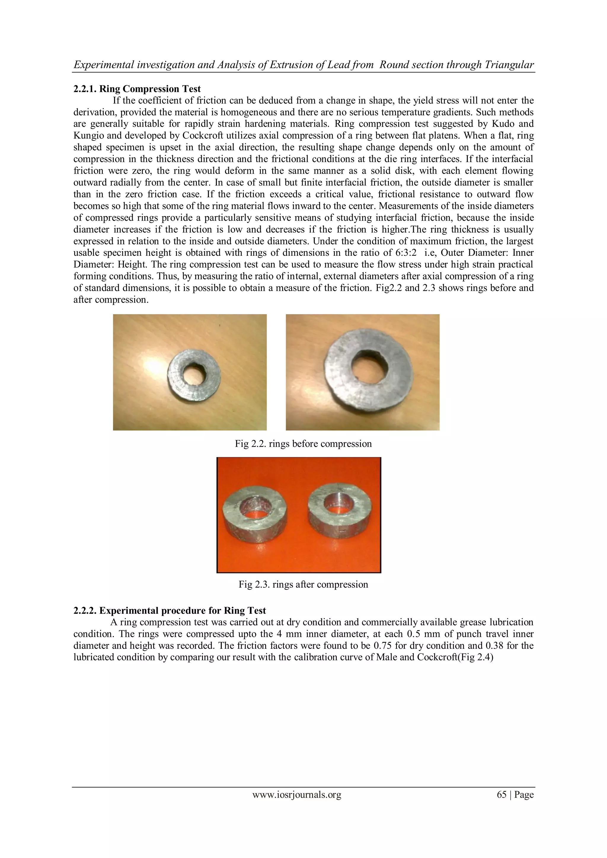
Before applying the theoretically result to any practical situation, their adequacy needs experimental
verification. The objective of present work is to compare theoretically predicted extrusion load with
experimental value. Experiments are performed for TRIANGULAR section using converging die.
Commercially available Lead was chosen as the working material for the experiments (extrusion). Different
shape of same circular entry face and various reduction of triangular exit face were made (60%, 70%, and 90%).
2.1.Determination of Material Behavoiur A serious limitation of the tensile test even for cold working is
that fracture occurs at a moderate strain; so that it is not possible to use this test for determination of yield stress,
after very heavy deformation. The fracture is most easily avoided by adopting some compressive form of test.
The average stress state during testing is similar to that in much bulk deformation process, without introducing
the problems of necking or material orientation. Therefore, in compression test, a large amount of deformation
can be achieved before fracture. By controlling the barreling of the specimen ends and the anvils with lubricants
the strain can be varied under limits.
2.1.1. Experimental procedure of Compression Test
Cylinders with a 50.20mm × 31.77 mm (H/D = 1.5 to 2) were used to obtain the stress-strain curve by a
compression test using UTM (INSTRON 400 KN) at room temperature. The compression rate is maintained
same as that adapted for the experiments. The specimen has oil grooves on both the ends to entrap lubricant
during the compression test. The compression load is recorded at every 0.5 mm of punch travel. After
compressing the specimen to about 10 mm it is taken out of the press, re-machined to cylindrical shape with
original diameter, and tested in compression till the specimen is reduced to about 10mm. The stress-strain
diagram is drawn and the curve is extrapolated beyond a natural strain 0.5. To simulate a rigid plastic material,
the wavy portion is approximated by smooth line (Fig. 2.1). The average flow stress of the used lead is found to
be 25460 KN/m2
.
Fig 2.1.variation of true stress with true strain
2.2.Measurement of Friction Factor The local value of the friction cannot be easily determined.
The coefficient of friction may actually vary through a working pass, as the lubrication deteriorates due to
thinning of the film and extension of their surface. Experimental studies suggests, however that this is negligible
for all well lubricated operations. There is at present no generally accepted method of measuring the value of the
coefficient of friction for given surface and lubricant. Various factors can influence the result, chemical
condition, lubricant film thickness; temperature, speed, environment and degree of deformation should match as
closely as possible the actual conditions of the operation. The friction factor can be measured by the following
methods.
• Direct measurement of friction in metal working.
• Coefficients obtained from correlation of theory.
• Measurements depending upon shape change.](https://image.slidesharecdn.com/i0636370-150115224838-conversion-gate01/75/Experimental-Investigation-and-Analysis-of-Extrusion-of-Lead-from-Round-Section-through-Triangular-Section-Converging-Dies-As-Applied-To-Forward-Metal-Extrusion-2-2048.jpg)
![Experimental investigation and Analysis of Extrusion of Lead from Round section through Triangular
www.iosrjournals.org 66 | Page
Fig 2.4. theoretical calibration curve for standard ring 6:3:2 [21]
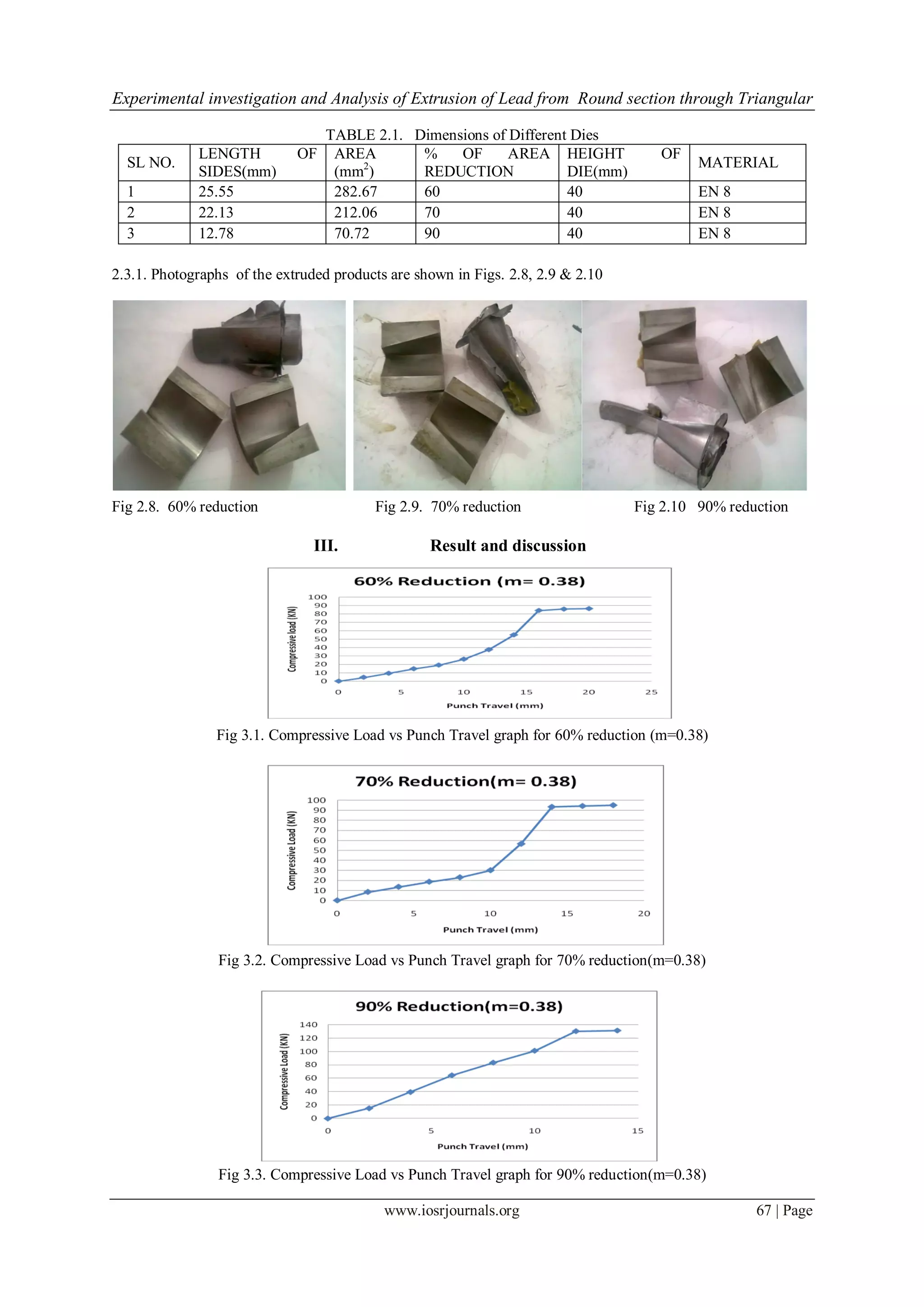
2.3.Design and Manufacturing of Extrusion Die
Fig 2.5. Converging die with 60% reduction
Fig 2.6. Converging die with 70% reduction
Fig 2.7. Converging die with 90% reduction](https://image.slidesharecdn.com/i0636370-150115224838-conversion-gate01/75/Experimental-Investigation-and-Analysis-of-Extrusion-of-Lead-from-Round-Section-through-Triangular-Section-Converging-Dies-As-Applied-To-Forward-Metal-Extrusion-4-2048.jpg)
![Experimental investigation and Analysis of Extrusion of Lead from Round section through Triangular
www.iosrjournals.org 70 | Page
Fig. 4.4 comparison of wet and dry extrusion pressure for extrusion of triangular sections
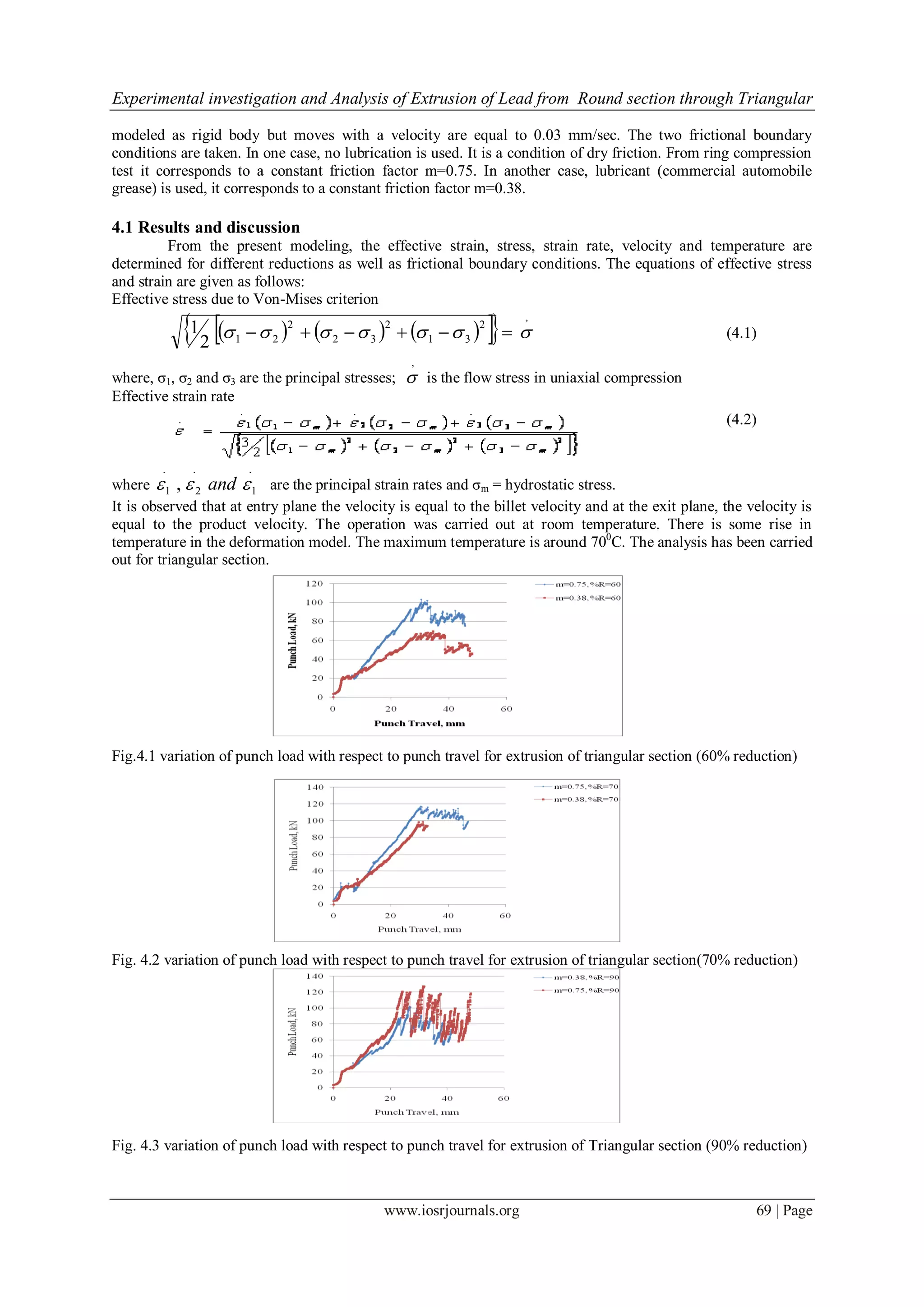
It is indicated that the extrusion pressure increases with increase in reduction and friction factor. It is observed
that the extrusion pressure is higher for dry friction.
V. Conclusion
In this study, a die profile function have been developed for extrusion of triangular section from round
billet using a mathematically converging die profile. Solid CAD models of converging die profiles have been
developed for extrusion of triangular section. FEM modeling have been carried out by using DEFORM-3D
software using tellurium lead as rigid plastic material for extrusion of triangular section from round billet.
Various extrusion parameters have been investigated to determine their effects on extrusion product. It was
found that extrusion pressure increases with increase in reduction and friction factor. Analysis of extrusion at
other different reductions may be carried out to compare the results.
References
[1] V. Nagpal, T. Altan, Analysis of the three-dimensional metal flow in extrusion of shapes. With the use of dual stream function, in:
Proceedings of the Third North American Metal Research Conference, Pittsburgh, PA, 1975, pp. 26–40.
[2] B.B. Basily, D.H. Sansome, Some theoretical considerations for the direct drawing of section rod from round bar, Int. J. Mech. Sci.
18 (1979) 201–209.
[3] D.Y. Yang, C.H. Lee, Analysis of three-dimensional extrusion of sections through curved dies by conformal transformations, Int. J.
Mech. Sci. 20 (1978) 541–552.
[4] W. Johnson, H. Kudo, The Mechanics of Metal Extrusion.(1963)
[5] Hill, Analysis metal working process, mechanics of physical solids flow rule(1963)
[6] R. Prakash, O.H. Khan, An analysis of plastic flow through polygonal converging dies with generalized boundaries of the zone of
plastic deformation, Int. J. Mach.Tool Des. Res. 19(1979)1-9
[7] P.K. Kar, N.S. Das, Upper bound analysis of extrusion of I-section bars from Square, rectangular billets through square dies, Int. J.
Mech. Sci. 39 (8) (1997) 925–934.
[8] S.K. Sahoo, P.K. Kar , K.C. Singh a. A numerical application of the upper-bound technique for round-to-hexagon extrusion through
linearly converging dies, Int. J. Mat. Pro. Tec. 91 (1999) 105–110
[9] Narayanasamy R, Ponalagusamy R, Venkatesan R, Srinivasan P (2006) An upper bound solution to extrusion of circular billet to
circular shape through cosine die. Mater Des 27(5):411– 415. doi:10.1016/j.matdes.2004.11.026
[10] J.S. Gunasekera, S. Hosino, Analysis of extrusion or drawing of polygonal sections through straightly conversing dies, J. Engng.
Ind.Trans. ASME 104 (1982) 38–43.
[11] C.B. Boer, W.R. Schneider, B. Avitzur, An upper bound approach for the direct drawing of square section rod from round bar, in:
Proceedings of the 20th International Machine Tool Design and Research Conference, Birmingham, 1980, pp. 149–155
[12] Knoerr, M. Lee,T.Altan, application of the 2D finite element method to simulation of various forming process, International
Journal of Materials Processing Technology,33(1-2), 1992,pp 31-55
[13] Kang, B-Soo, Min-Kim,B. and Choi, J.C., perform design in extrusion by the FEM and its experimental confirmation, International
Journal of Materials Processing Technology,41(2),1994,pp 237-248.
[14] A. K. Rout and K. P. Maity, Numerical and Experimental study on the three-dimensional extrusion of square section from square
billet through a polynomial shaped curved die, published in an Int. J. of Advanced Manufacturing Technology, Vol-54, Issue 5,
(2011), pp. 495-506.
[15] Johnson W, Experiments in the cold extrusion of rods of non-circular sections, Journals of Mechanics and Physics
Solids,5,1957,pp.267-281.
[16] D.Y. Yang, M.U. Kim, C.H. Lee, A new approach for generalized three-dimensional extrusion of sections from round billets by
conformal transformation, IUTAM Symp. Metal Forming Plasticity, Germany, 1979, pp. 204–221.
[17] Geoffrey W. Rowe, Introduction to the principle of metal working, Chapter-8
[18] V. Gopinathan, Plasticity Theory and its Application in Metal Forming, Chapter 7
[19] Dieter,G.E., Mechanical Metallurgy (Tata McGraw-Hill Publishing company ltd., New Delhi)
[20] DEFORM TM
3D Version 6.1(sp2),User’s manual, Scientific Forming Technologies Corporation,2545 Farmers Drive, Suite 200,
Columbus, Ohio,2008,43235.
[21] Shabaik. A. and Kobayashi. S., Computer application to the viscoplasticity method, Transactions of the ASME, Journal of
Engineering for Industry,89,1967, pp.339-352.](https://image.slidesharecdn.com/i0636370-150115224838-conversion-gate01/75/Experimental-Investigation-and-Analysis-of-Extrusion-of-Lead-from-Round-Section-through-Triangular-Section-Converging-Dies-As-Applied-To-Forward-Metal-Extrusion-8-2048.jpg)

The document presents an experimental investigation into the extrusion of lead from round sections through triangular section converging dies, analyzing die angle changes, area reductions, and loading rates on extruded products. It includes a detailed study of extrusion pressure, finite element analysis, and various experiments to verify theoretical predictions using different die profile configurations. Results indicate that extrusion pressure increases with higher reductions and friction factors, emphasizing the efficiency of the proposed extrusion method.


