
Recommended
Recommended
More Related Content
What's hot
What's hot (20)
Similar to Papers review for Flame Stability
Similar to Papers review for Flame Stability (20)
More from Jameel Tawfiq
More from Jameel Tawfiq (7)
Recently uploaded
Recently uploaded (20)
Papers review for Flame Stability
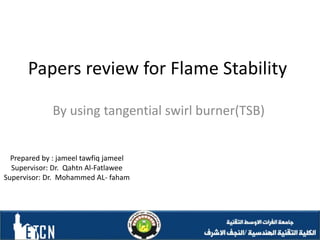
- 1. Papers review for Flame Stability By using tangential swirl burner(TSB) Prepared by : jameel tawfiq jameel Supervisor: Dr. Qahtn Al-Fatlawee Supervisor: Dr. Mohammed AL- faham
- 2. My notes or lines 1. How to get the combustible stability of the flame. 2. As well as reducing polluting emissions to the environment. 3. Work on designing modern combustion burner techniques to avoid combustion problems.
- 3. Experimental Burner Rig Setup A tangential generic swirl burner of a thermal capacity up to 150 kW, figure 3-1, has been used to investigate different flame flashback mechanisms. The system has two circular tangential inlets of 67 mm diameter each. The inlet area can be varied by using different inserts (25-25), (50-50) and (70-70) respectively in order to achieve variable swirl numbers. The system can also be used with three different nozzle configurations varying the exhaust diameter from 62 to 76 mm. Air was provided by a centrifugal fan via flexible hoses and two banks of rotameters to control the air flow rate. Another bank was used for natural gas injection
- 4. The burner baseplate is designed mainly to allow central fuel injection in order to start burner operation. During stable operation, both air and gas are injected tangentially. Premixed gas injectors extend across the inlet ducts to allow adequate mixing. central fuel injectors are extended from the baseplate through the centre of the burner plenum opening just before the nozzle. The approach considers the following assumptions: 1. Isothermal conditions 2. Constant static pressure across the exit 3. Constant density throughout the burner 4. Uniform axial velocity in the exhaust
- 6. Introduction This article reviews the scientific issues associated with operating steady flowing combustors on syngas, such as gas turbines, boilers, and furnaces. A number of important practical problems must be dealt with in developing a combustion system capable of combusting syngas, particularly if the system must also emit low levels of •CO and NOx emissions.
- 7. •Some of these issues are well understood •and utilize well-developed engineering knowledge, such as required line or orifice sizes needed to pass a given fuel flow rate in order to supply the combustor with a given heating rate. There are a number of other issues, however, substantially less well understood, which involve complex interactions between fundamental combustion phenomenon and fluid mechanics. In particular, burners involve complex, poorly understood interactions between swirling flow dynamics, propagation.
- 8. In related fashion, there are a number of operability issues related to operating the combustor in a safe, efficient, and reliable manner. This includes having the combustor reliably hold the flame so that it neither flashes back nor blows out, and burns the fuel in a ‘‘quiet,’’ steady fashion. We briefly review four of the most critical of these operability issues below, all of which are strongly influenced by fuel properties:
- 9. This article addresses: Blowoff , Autoignition Flashback Combustion instability
- 10. tangential swirl burner(TSB) (TSB) system consists from : • Tangential swirl burner system . • Central air / fuel injector pipe . • Stand to fixed the system. • Cylinder gas (LPG). • Compressor air • Thermal camera . • Sensor to avoid flashback.
- 11. Blowoff Blowoff means the flame is being detached from its stable position and physically blown out. The most common reason that can cause flame blowoff is very lean mixtures or robust combustion instabilities. Recently swirl combustors have been Extensively employed with lean premixed combustion to reduce NOx emissions, which are required to operate close to their blow off limits, hence the strong possibility of being subjected to this issue.
- 12. This problem becomes significantly important, especially for aircraft engines. Blow off is a complicated phenomenon that involves interaction between chemical reactions, flame propagation and flow dynamics. Blow off phenomena have been extensively investigated, and a variety of experimental techniques and numerical simulations have been employed to achieve better understanding to prevent its occurrence It is thought that blow off is governed by the equilibrium between chemical kinetics and fluid mechanics. Thus this relation can be described by using a Damköhler number based on a well-stirred reactor which represents the relation between residence time and chemical kinetic time
- 13. Da=τu/τc Where τu : The period that reactants remain in the reaction zone or flow time scale [s] τc : The required time for chemical reaction [s] Thus blow off will occur if the residence time is shorter than the chemical time. The residence time is denoted by the ratio between the characteristic length (recirculation zone), and the characteristic velocity scale, while chemical time scale represents the ratio between thermal diffusivity, and laminar flame speed SL, thus blow off can be correlated with the Damköhler number as follows:
- 14. Where Da : Damköhler number [-] d : characteristic length (recirculation zone length) [m] Ub : average bulk burner exit axial velocity [m/s] α : thermal diffusivity [m2/s] SL : Laminar flame speed [m/s]
- 15. However, determining the characteristic velocity, the characteristic length and hence the residence time is not simple. The characteristic velocity is a function of approaching flow velocity Ub which may change with Reynolds number due to changes in burning gas temperature while the characteristic length is a function of the recirculation zone shape. Additionally, calculations of thermal diffusivity for a fuel of different blends is sophisticated. Hence the evaluation of chemical time scale becomes more complex. This investigation of the chemical kinetic is not sufficient to have a comprehensive understanding about blow off; fluid mechanics must be accounted too.
- 16. Nonetheless, blow off trends of a wide range of fuel compositions can be determined by using the Damköhler number The relation between flame strain and blow off can be used to predict the mechanism of blow off. Whereas flame strain occurs under certain levels of flow velocity gradients and it can withstand limited levels of strain before extinction, this level is denoted by an extinction strain rate Kext which is a function of the fuel composition, chemical time scale and stoichiometry, thus Damköhler number can be written as follows;
- 17. Da=Kext/K Kext : extinction strain rate [1/s] K : flame stretch Many mechanisms can be used to enhance flame resistance to blow off. Swirl burners and bluff-body techniques have been employed in many applications to achieve flame stability. They can work as premixed flame holders, enabling mixing between combustible mixture with hot combustion gases and promote the continuous ignition of reactants
- 18. The flame holding represents a crucial factor in flame stability. Consequently, many studies have demonstrated different characteristics of flame holding and its effect on blowoff limits by using bluff-bodies. Lieuwen, et al. studied the effect of bluff-body geometries. The team pointed out that vortex shedding results from the bluff-body playing an important role in the ratio of gas expansion across the flame and hence the level of flame extinction, and as a consequence the blowoff mechanism. Roy Chowdhury and Cetegen correlated the turbulence level with strain rate; they found that strain rate increased with increasing turbulence, consequently leading to localised extinction zones along the flame surface .
- 19. Chaparro and Cetegen [122] also indicated that blowoff equivalence ratios are affected directly by upstream flow extinction. Due to recent trends from using lean premixed combustion and alternative fuels, introducing hydrogen or high hydrogen blends as alternative fuels have increased significantly. Blowoff and flame extinction limits are directly proportional to the percentage of the hydrogen content of a certain fuel. Many studies have proven that the equivalence ratio at which blowoff occurs can be decreased by increasing hydrogen percentage Working at this conditions enables burners to operate at lower flame temperatures consequently low NOx emissions
- 20. Autoignition Under certain conditions inside the premixer such as high pressure or high temperature, it is possible that the mixture ignites without an external energy source this occurs especially in premixed flows an increase in temperature may be caused by early incidence of chemical reactions of the mixture inside the premixer at high pressure and/or high temperature. This results in considerable amount of heat generation leading to spontaneous ignition. In general, autoignition is defined as the homogeneous ignition of the combustible mixture upstream of the combustion chamber
- 21. Autoignition is a serious issue that can stain the performance of gas turbines and can cause considerable damage to the system. Thus it is crucial to predicting the ignition time of each mixture to achieve more secure operation conditions. Autoignition time delay is defined as the time interval between the injection of the mixture into the combustion chamber and the onset of the flame. This time can be represented using Wolfer equation Where ti : the ignition time delay [ms] P : the pressure [bar] Tm : the initial mixture temperature [K]
- 22. Nevertheless, in addition to the effect of pressure and temperature, fuel composition plays an important role in determining the autoignition time delay. Natural gas or methane is the favourable fuel for stationary gas turbines and has reasonably weak ignition behaviour at low temperatures. However, this behaviour can be affected drastically when adding higher hydrocarbon blends. Recently, hydrogen has proved to be a clean energy carrier, and it can be added to natural gas or methane to enhance some operational requirement, as a consequence of its delay time, wide flammability limits, high energy density and high laminar flame speed.
- 23. However, the percentage of hydrogen addition significantly impact the autoignition mechanisms. The higher the hydrogen concentration, the more the hydrogen chemistry dominates the mixture ignition, whereas the non-linear relationship between logarithmic of ignition delay and equivalence ratio becomes increasingly evident with increasing hydrogen fraction In swirl combustors, strong aerodynamic effects are directly linked to predicting autoignition times. However, weak aerodynamic system designs make them more likely to suffer flashback. Thus, ignition delay times of the fuel used and the local conditions should be taken into consideration when designing the premixer to avoid autoignition
- 24. Flashback Flashback is the upstream flame propagation from the combustion zone to the premixing zone inside the combustor. It occurs when the flame speed exceeds the approaching flow velocity [39]. Flashback is a main operability issue and an inherent instability problem of lean premixed combustion systems which can cause the burner to overheat with considerable damages to the system hardware and increase in pollutant emissions [68, 140, 141] as can be seen from figure 2.5.
- 25. Fuel composition represents an important factor affecting flashback mechanisms. This effect is characteristic of turbulent flame speed ST variations. Thus introducing hydrogen or hydrogen fuels to premixed combustion systems that use swirl combustors have brought many concerns regarding flashback. More reactive gases than a natural gas such as hydrogen can present flame speeds about four times greater than those of natural gas. Swirl lean premixed flames are more likely to be subjected to flashback. Swirling flows are complex and can interact with the flame in these systems causing flame flashback.
- 26. Figure 2-5. System hardware damages due to flashback.
- 27. According to previous literature, there are four types of flashback mechanisms Boundary Layer Flashback This type of flashback was firstly described by. They investigated laminar non-swirling flow flashback, pointing out that the reason of flame flashback in the wall boundary layer is due to the reduction of the approaching flow velocity near the wall in such way that it became lower than the flame speed. Thus, they proposed the so- called “Critical gradient” model. This model defines the flashback limits according to the equilibrium between the wall-parallel boundary layer velocity u(y), where (y) represents the wall - normal coordinate and the flame speed Sf (y) at a distance dq from the wall which represent the quenching distance, as can be seen in figure 2.6.
- 29. Recently Lin, et al. [149] proposed a methodology for correlating the flashback propensity with turbulent flame speeds (ST) for H2 rich gases based on measurement of critical velocity of the flame and flow as follows gc : the critical velocity gradient of the flame [1/s] Le : Lewis number which represents the ratio between thermal diffusivity to mass diffusivity [-] δlo : (un-stretched) laminar flame thickness [m] The critical velocity gradient of the flow is represented by the following equation; gf=0.03955×Ub74⁄×υ-3/4⁄×d1/4
- 30. gf : the flow velocity gradient [1/s] Ub : the bulk velocity at the combustor inlet [m/s] υ : the kinematic velocity of the combustible mixture [m2/s] d : the diameter of combustor inlet [m] Thus, according to these relations, the flame stability depends on the balancing between (gf) and (gc), whereas flashback takes place when (gc) exceeds (gf). Turbulent Core Flashback Turbulent core flashback takes place when the turbulent flame velocity (ST) exceeds the local flow velocity in the core flow .
- 31. Then the flame can propagate upstream in all the zones of the burner that have lower velocities than the turbulent flame speed. Thus one of the fundamental design parameters of new burners is how to ensure that flow fields do not have strong local velocity deficits with axial flow velocities that must be higher than the turbulent flame speed (ST). Turbulent flame velocities depend on chemical kinetics, turbulent structures, length scales and velocity fluctuations. Although, there is vast literature on different techniques and simulations to predict the turbulent flame velocity of various combustion systems, there is still a crucial need to have a more practical and robust methodology for investigating turbulent flame velocity especially for H2-fuels. Consequently, designing combustion systems to have a higher axial flow velocity, hence avoid turbulent core flashback, is still based on practical experience
- 32. Flashback due to Combustion Instabilities and Coherent Structures Combustion or thermo-acoustic instabilities inside the combustion chamber can cause upstream flame propagation both in the turbulent core and boundary layer, consequently flame flashback. These types of instabilities arise when unsteady or periodic heat release couples with one or more acoustic modes of the combustor. It is possible for these oscillations to interfere with the combustion system causing a considerable amount of vibrations which lead to failure or collapse of the combustion system. one of these mechanisms is high pulsation levels, which cause a modulation of the flow field in the burner
- 33. Another cause of instabilities is equivalence ratio perturbations which have a direct effect on a chemical reaction, flame speed and indirectly on the flame area which in turns control the amount of heat release response. Swirling flows and their coherent structures, especially the precessing vortex core (PVC), also represent another source of unsteadiness or fluctuation.
- 34. Flashback due to Combustion Induced Vortex Breakdown (CIVB) Combustion induced vortex breakdown has been identified as one source of sudden flame transition and flashback in swirl combustors. This sudden transition can cause severe system failure due to the risk of overheating of upstream burner positioned components. This type of flashback is substantially different from the previous three flashback types. It occurs primarily in swirl stabilised combustors without a centre body at stable operation due to small changes in the flow field and the interaction of the turbulence and chemistry at the tip of the central recirculation zone [65, 160, 161]. It can occur even if the flow velocity is higher than the turbulent flame speed [162]. The earliest study that denotes this phenomenon was done by Kröner, et al. [66]. The group investigated the flashback limits for swirl burners with cylindrical premixing tubes without using centrebodies
- 35. They found that the quenching effect of chemical reactants plays the dominatn role in flashback limits. Another study [65] found that flame propagation is governed by mutual feedback between chemical reaction and flow. In other words, flashback has high sensitivity to the momentum distribution in the vortex core, whereas the chemical reaction leads to variation in pressure boundary conditions at the inlet of the combustion chamber, consequently, promoting the propagation of the vortex breakdown. The study has proved the possibility of significant flashback resistance mechanisms when introducing axial jets, however, altering swirl levels. The effect of the axial jet has also been investigated by [163] who found that the increase in axial jet diameter leads to thicker vortex cores. Hence the vortex breakdown will be shifted downstream and consequently stabilise the burner operation window.
- 36. They also correlated the phenomenon of stagnation of the recirculation zone with the effect of changing the equivalence ratio of the axial position. Based on their investigations the upstream flame envelope and the stagnation point play the dominatn role in the onset of the CIVB. If the recirculation zone can pass the stagnation point in the upstream direction, the volume expansion upstream of the recirculation zone generates positive azimuthal vorticity consequently positive axial velocity. Thus stable flame prevents the occurrence of the CIVB. However, upon further upstream flame propagation (a further increase of equivalence ratio) baroclinic torque will increase, thus the high possibility of CIVB occurrence increases as well.
- 37. Kröner, et al. [66] proposed a new correlation to define flashback limits. This correlation stated that flame quenching occurs at a critical value of the quench parameter (Cquench) which represents the ratio between the characteristic chemical time scale (τc) and flow or mixing time (τu)
- 38. The end
Editor's Notes
- Hybrid الهجين