
Recommended
Recommended
More Related Content
What's hot
What's hot (18)
Similar to Co2 gas flotation of waste activated sludge using weak vacuum pressure with thermal treatment
Similar to Co2 gas flotation of waste activated sludge using weak vacuum pressure with thermal treatment (20)
Recently uploaded
Recently uploaded (20)
Co2 gas flotation of waste activated sludge using weak vacuum pressure with thermal treatment
- 1. CO2 GAS FLOTATION OF WASTE ACTIVATED SLUDGE USING WEAK VACUUM PRESSURE WITH THERMAL TREATMENT M. El_zahar*, M. Salih** and K. Fujisaki* * Department of Civil Eng., Kyushu Institute of Tech., 1-1 Sensuicho, Tobataku, Kitakyushu, 804-8550, JAPAN ** Department of Civil Eng., Faculty of Eng., University of Suez Canal, Port Fouad, Port Said, EGYPT ABSTRACT An experimental model was prepared to confirm the usefulness of dissolved CO2 gas flotation of waste activated sludge. The target of this research is to develop a high efficiency flotation system using low vacuum pressure with thermal treatment. The water solubility of CO2 gas is 20-30 times larger than that of air. Using this unique property of CO2 gas, we have tried the CO2 pressurized gas flotation of waste activated sludge and succeeded to large extent. Using small amount of vacuum pressure, CO2 flotation with thermal treatment was executed. By this method the flotation efficiency was improved; furthermore, the volume of waste activated sludge was decreased and the final moisture content of the waste activated sludge was also decreased. To generate the micro bubbles, the vacuum pressure can be set at too small values compared with that of the conventional methods of vacuum flotation. Using low vacuum pressure, CO2 bubbling was examined experimentally. Some additional thermal treatment also enhanced its efficiency and was effective to decrease the final moisture content of the waste activated sludge. Thus, the possibility of using this idea for treatment plants was achieved. KEYWORDS Carbon dioxide; dissolved gas flotation; thermal treatment; vacuum flotation, waste activated sludge INTRODUCTION The conventional vacuum flotation methods consist of saturating the wastewater with air either directly in an aeration tank or by permitting air to enter on the suction side of a wastewater pump. Then, a partial vacuum pressure is applied, which causes the dissolved air to come out of the solution as minute bubbles. The generated micro bubbles rise to the surface with the attached solid particles to form floated scum blanket (George et al., 1991). Because the usefulness of CO2 gas flotation of waste activated sludge had been partly confirmed by one of authors (Fujisaki et al., 1997), we used CO2 gas instead of air as a saturating gas for the sludge. Then, a partial vacuum pressure is applied for a short time to help the micro bubbles generation. To improve the flotation efficiency, some thermal treatment is added using circulation of hot water around the flotation cell indirectly. The main target of this paper is to develop a high efficiency flotation process by adding the thermal treatment to the combined process of vacuum and pressurized CO2 gas flotation of waste activated sludge. EXPERIMENT AND MODEL DESCRIPTION All samples used for experiments were waste activated sludge taken from the municipal sewage treatment plant that is located in Kitakyushu city. Its moisture content was 0.9960~0.9985. The SVI was about 200 ml/g and the pH value of all experiments ranged between 6.4~7.1 depending on the internal temperature of the waste activated sludge. The samples were exposed to air to insure full aeration for the sludge. As shown in Fig.1, the experimental model consists of two parts. The first part was used to
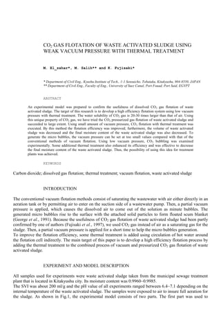
- 2. dissolve CO2 gas into the waste activated sludge using the gas and liquid circulation method (El_zahar et al., 2000). The inner diameter of the pressurised tank was 10 cm. It was found that, a range of gauge pressure between 40~80 kPa is enough to dissolve CO2 with using liquid circulation method (Fujisaki, 1997; El_zahar et al., 2000). The second part, the flotation cell was a closed acrylic pipe of a 6.4 cm inner diameter and 100 cm length. The flotation cell has three openings for adding the sludge, exposing to the vacuum pressure, and measuring the gauge pressure. Furthermore, the flotation cell was surrounded by cylindrical water jacket to control the temperature out of the sludge using circulation method. The typical procedure, for one run, 4 litres of waste activated sludge are used and a flow rate of CO2 gas for sludge saturation equals 2 lit. /min. For generation of the fine micro bubbles of CO2 gas, the waste activated sludge was bubbled for 6 minutes and, in each run, the bubbling pressure was kept constant as shown in Table 1. The bubbled waste activated sludge was then transmitted to the flotation cell, and a vacuum pressure was exposed to the specimen for 90 seconds. The micro bubbles that attach to the waste activated sludge solid particles, rise to the surface to form floated scum blanket of the floated sludge. Some thermal treatment was added by using hot circulated water around the sludge to 40 and 50o C. The pressure difference brought the micro bubbles to go out of the solution. Fig.1 Experimental Model Fig.2 CO2 gas solubility versus pressure Figure 2 shows the relation between the saturating pressure and the CO2 gas solubility which is plotted according to Henry`s law. As shown in Fig. 2, if we set a definite value of bubbling pressure of CO2 gas with the sludge and then release this value to atmospheric pressure, then we can estimate the amount of CO2 micro bubbles generated. In order to get more effective CO2 micro bubbles, we tried a new method in which the sludge was exposed into a small value of vacuum pressure instead of just release the pressurized sludge into the atmospheric pressure. This method would give more effective CO2 micro bubbles. Moreover, it could increase velocity and efficiency of the flotation process. The ratio between CO2 gas A and the solids of the waste activated sludge S by weight which is called gas solid ratio was, A/S =0.04. Table 1 shows the experimental conditions for all runs of experiments, in which Bp is the used bubbling pressure; Ho is the initial flotation height for every run and Temp. is the temperature degree used for thermal treatment. Sludge Gauge scale Separated liquor Separated sludge CO2 gas Floated sludge Separated Liquor H D Ho Circulated water zone Water basin Gauge scale (a) 100 cm (b) (P) Vacuum pressure H* (a) Flotation cell (b) Pressurized tank (P) Pump 0 1 2 3 4 5 6 0 1 2 3 4 CO2 gas solubility in water (cc/cc) 0 o C 10 o C 20 o C 30 o C 40 o C 60 o C Pressure (kgf/cm2 )
- 3. Table 1 Experimental Conditions Exp. No. Bp Ho Vp Temp. (kPa) (cm) (kPa) (o C) 1, 2, 3 80, 60, 40 73, 75, 71 -4.0 50 4, 5, 6 80, 60, 40 72, 69, 70 -4.0 40 7, 8, 9 80, 60, 40 70, 69, 69 -4.0 No* 10, 11, 12 80, 60, 40 70, 69, 69 -2.0 50 13, 14, 15 80, 60, 40 70, 70, 69 -2.0 40 16, 17, 18 80, 60, 40 69, 69, 69 -2.0 No* 19, 20, 21 80, 60, 40 70, 70, 69 0.0 50 22, 23, 24 80, 60, 40 70, 70, 70 0.0 40 25, 26, 27 80, 60, 40 70, 69, 70 0.0 No* Where, kPa = 0.01 kgf/cm2 * No means flotation at room temperature (around 20o C) RESULTS AND DISCUSSION Figure 3 shows the effect of time of exposure for vacuum pressure on flotation process. It is a simple flotation curve shows the relationship between time in minutes on x-axis and the ratio between the flotation height and initial height of sludge at any time t. At first we checked exposure time of vacuum pressure, 3 min. and 1.5 min. (90 sec.). As shown in Fig. 3 the initial flotation speed was almost same but for the final concentration of the sludge, 90 seconds case gave higher results. The reason was that the long vacuum period produced extra number of CO2 micro bubbles. These micro bubbles had risen quickly to the surface. Fig.3 Effect of vacuum time on flotation process 0 10 20 30 40 50 60 70 80 90 0 10 20 30 40 50 Time (min.) (H/ Ho) % Vac. time = 3 min. Vac. time = 1.5 min. Vacuum pressure = -4 kPa, Temp. = 50o C
- 4. Furthermore, they were not able to attach to the solid particles, which resulted in a decrease of flotation efficiency. On the other hand, case of 90 seconds produced sufficient number of micro bubbles with suitable speed to float the sludge solid particles. Compared with the flotation results that had been gotten in the last papers (Fujisaki, 1999; El_zahar et al., 2000). It had been observed that, small value of vacuum pressure (-2 or -4 kPa) was effective to produce uniformly distributed CO2 micro bubbles, that resulted in stable, fast and uniform flotation with no settling at all. As shown in Fig. 4 and Table 2, after only 15 minutes from start of the flotation, the separated liquor zone grew to 60-80 % of its initial height Ho. Furthermore, the percentage of H15/H40 ranged from 78-97 %. Fig.4 Examples of vacuum flotation process curves with thermal treatment This phenomenon means that the required full flotation period can be reduced to very short time compared with conventional methods of flotation of waste activated sludge. The thermal treatment is effective to decrease the moisture content of the separated waste activated sludge specially in case of using 50o C temperature of treatment. The moisture content ranged between 96.3-97.8 %. Moreover, the waste activated sludge was concentrated by 7-10 times as shown in Table 2 in which Cs shows the volume reduction ratio of sludge after flotation. These results were obtained using small vacuum pressure of –4 kPa only for 90 seconds, i.e. the energy saving will be possible in the practical case. Table 2 Summary of the best flotation results Exp. No. Bp Temp. Vp H15/H40 H40/Ho Mc Cs Vif (kPa) (o C) (kPa) % % % % Cm/min. 1 80 50 -4 96.1 82.2 96.7 79.5 51.6 2 60 50 -4 97.2 75.7 96.9 70.4 44 3 40 50 -4 94.8 78 96.3 73.8 30.5 4 80 40 -4 97.5 80 97.1 78.6 48.2 6 40 40 -4 91.5 76.5 98.6 76.5 12.5 9 40 No -4 96.1 77.4 98.3 77.4 9.6 10 80 50 -2 90.4 78.6 97.6 77.1 19.8 19 80 50 0.0 93.8 83.7 97.6 78.6 5.2 20 60 50 0.0 88.3 77.9 97.8 77.9 1.4 21 40 50 0.0 78.3 76.6 98 76.6 1.57 Vacuum pressure = -4 kPa, Temp. = 50o C Vacuum pressure = -4 kPa, Temp. = 40o C 0 10 20 30 40 50 60 70 80 90 0 10 20 30 40 50 Time (min.) (H/Ho) % Bubb. Pre. (80) Bubb. Pre. (60) Bubb. Pre. (40) 0 10 20 30 40 50 60 70 80 90 0 10 20 30 40 50 Time (min.) (H/Ho) % Bubb. Pre. (80) Bubb. Pre. (60) Bubb. Pre. (40) 0 10 20 30 40 50 60 70 80 90 0 10 20 30 40 50 Time (min.) (H/Ho) % Bubb. Pre. (80) Bubb. Pre. (60) Bubb. Pre. (40) 0 10 20 30 40 50 60 70 80 90 0 10 20 30 40 50 Time (min.) (H/Ho) % Bubb. Pre. (80) Bubb. Pre. (60) Bubb. Pre. (40)
- 5. Where, ) H ) H H ( 1 ( 100 % C o 40 * s The waste activated sludge volume was reduced into 70-80 % after 40 minutes only from start of the flotation. The initial flotation velocity after 1-3 minutes was very fast about 5-30 cm/min compared with the value of conventional methods 0.5-2 cm/min. (El_zahar et al., 2000). Thus, the initial flotation velocity was about 10-20 times faster than the case of no vacuum pressure (conventional pressure release flotation methods (George et al, 1991)). CONCLUSIONS From Table 2, Figures 3 and 4, and the previous discussion we can summarize the following: [1] The vacuum flotation by CO2 gas instead of air with thermal treatment was successfully developed, so the target of the research was achieved. [2] The waste activated sludge was concentrated by 7-10 times after 40 minutes of flotation. [3] The turbidity of the separated liquor was too small to be measured. [4] The pH value of the separated liquor after flotation ranged between 5.3-5.7. [5] The time of full flotation can be reduced to 20 minutes only to get same or higher efficiency as conventional methods. [6] Thermal treatment with 40-50o C is effective to get higher dewaterability of the waste activated sludge. These results had shown that vacuum flotation is promising process for practical use specially with using CO2 gas instead of air. Nomenclature Bt = Bubbling time [min.] Bp = Bubbling pressure [kPa] Vp = Vacuum pressure [kPa] Ho = Initial height of sludge [cm] D = Diameter of flotation cell [cm] Cs = Volume reduction ratio of sludge after flotation [%] Vif = Initial flotation velocity (flotation rate after 1-3 min.) [cm/min.] Mc = Moisture content of waste activated sludge after the flotation [%] H15 = Height of separated liquor after 15 minutes from the flotation starting [cm] H40 = Height of separated liquor after 40 minutes from the flotation starting or final flotation height [cm] H = Flotation height at any time t [cm] H/Ho = Flotation ratio at any time t [-] H40/Ho = Final flotation ratio after 40 minutes from the flotation starting [-] A/S = Gas solid ratio [-] ACKNOWLEDGEMENT Many thanks are due to master course student Masato Takanishi for his help in the experimental work in water treatment laboratory of Kyushu Institute of Technology. REFERENCES El_zahar M., Takanishi M., Salih M., Fujisaki K. and El_hattab I. (2000) Experimental studies on flotation of waste activated sludge using carbon dioxide with thermal treatment. Proceedings of water supply and water quality conference IV-TH, Kracow, Poland, Vol. 1, 649-659 Fujisaki K. (1999) A basic study on vacuum flotation of waste activated sludge. RESOURCES PROCESSING, The Resources Processing Society of Japan, ISSN 0912-4764, Vol. 46, 19-23, (In Japanese) Fujisaki K. and Shinji N. (1997) A basic study of the flotation of waste activated sludge by use of carbon dioxide. Environmental engineering research. Vol. 34, (In japanese)
- 6. Fujisaki K. and Shinji N. (2000) Dissolved gas flotation of waste activated sludge by use of carbon dioxide. Proceedings of the 8th world filtration congress, Brighton, UK, Vol. 1., 119-122. (WFC8 conference proceedings) George T. and Franklin L. B. (1991). WASTE ENGINEERING “treatment, disposal and reuse.” 3rd edn, Mcgraw_Hill, Inc. James K. E. (1995) Principles and applications of dissolved air flotation. Water science technology, Vol. 31, No. 3-4, 1-23, (IAWQ conference proceedings) Kenneth J. I. (1984) The scientific basis of flotation. 1st edn, Netherlands Nicholai N. V. and Igor A. D. (1997) Classification of flotation processes in wastewater decontamination. Journal of environmental engineering, No. (5), (ASCE, ISSN Conference proceedings; 124)