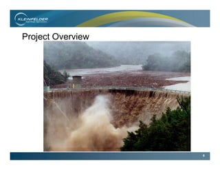
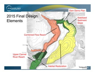
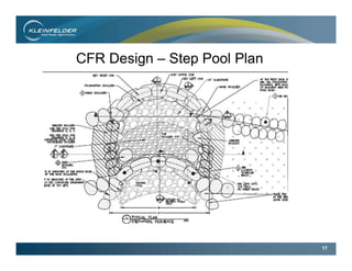
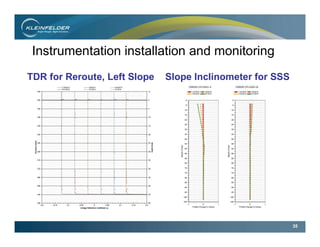
The Final Phase of San Clemente Dam –
Removal and Stream Restoration
Godwin, W. , Waeber, J. , Wade, D, and McGowan, W
Annual Meeting, Association of Environmental &
Engineering Geologists– Kona, Hawaii
September 21, 2016 Technical Session #1
Presented By:
William Godwin, P.G., C.E.G.
2
Outline
Project Location and History
Project Overview
Geology
Final Design Elements
Final Construction Phases
Dam Removal(s)
Instrumentation and Monitoring
Questions
3
Project Location
4
History of San Clemente Dam
Constructed between 1920
& 1921 by PIC
Owned and operated by
California American Water
Built for drinking water
storage for Monterey
Peninsula
Fish ladder added later
5
Built in V-notch canyon
below confluence of San
Clemente Creek and
Carmel River
Concrete arch dam
106 feet high
300 foot width
1425 acre-feet – now 70
acre-feet
Over 2.5 million cubic yards
of sediment
History of San Clemente Dam
6
Project Overview
7
Project Overview
1990’s CDWR – DSOD issued safety order
Potential failure during MCE (7.0M Tularcitos fault) or PMF
2006 released a draft EIS
EIR Alternatives:
Dam Strengthening ($50M)
Dam Removal
2008 CAW – preferred removal of the dam. Benefits: fish
access, sediment replenishment, removal of hazard
Previous investigations by URS, MWH, Woodward-Clyde
and Kleinfelder
URS provided an indicative design
8
Combined Flow Reach
Upper San Clemente Creek
Reroute Channel Sediment
Stockpile
Upper Carmel
River Reach
Former Location
Of Dam
Diversion Dike
Stabilized
Sediment
Slope
Project Overview - Layout
9
Project Overview – Key Stakeholders
$83M cost
Funding: California
American Water
California Department of
Fish & Wildlife
California Natural
Resources Agency
California Wildlife
Conservation Board
California State Coastal
Conservancy
National Marine Fisheries
Service – NOAA
Resources Legacy Fund
The Nature Conservancy
United States Fish &
Wildlife Service
10
Project Overview – Project Team/Schedule
Granite Construction –
General Contractor
Kleinfelder – Engineer of
Record (EOR) and lead
Civil/Geotechnical designer
Tetra Tech – H/H modeler,
Channel Restoration design
Rana Creek, Habitat
Restoration
Oversight
AECOM – Owners Engineer
WSC – Construction Mgr.
2013 Season:
Geotechnical
Investigation, initial
diversion structures,
overall design
2014 Season: Reroute
Cut, Diversion Dike,
Sediment Stockpile,
design/construct
2015 Season: Stabilized
Sediment Slope, dam
removal, CFR channel
design/construct
11
Regional Geology
Jennings 2010
12
Site Geology
History of Dam
Project Background
Project Overview
Geology of Location
Geotechnical Investigation
Challenges
Summary
Dibblee, T.W., and Minch, J.A.,“Geologic map of the Carmel Valley quadrangle, Monterey County, California,” published by Dibblee Geological
Foundation in 2007,
Accessed from http://ngmdb.usgs.gov/Prodesc/proddesc_83298.htm
Lt Mesozoic
Granodiorite
Lt Mesozoic
Granodiorite
Early Mesosoic
Metasedimentary
& Granitic Rocks
Lt Mesozoic
Quartz Monzonite
Miocene
Sandstone
Lt Mesozoic
Quartz Diorite
Early Mesosoic
Metasedimentary
& Granitic Rocks
13
Combined Flow Reach
Habitat Restoration
Upper Carmel
River Reach
Dam Demo Plan
Stabilized
Sediment
Slope
2015 Final Design
Elements
14
Diversion Dike (DD) Design
15
Stabilized Sediment Slope (SSS) Design
16
Combined Flow Reach (CFR) Design
17
CFR Design – Step Pool Plan
18
CFR Design - Step Pool Elevation
19
Construct Combined Flow Reach
Restore San Clemente Creek
Reroute Rock Sill
Top off Sediment
Stockpile
Grade Upper Carmel
River Reach
Remove Dam and
Slide Debris
Remove Diversion Pipe and Cutoff
Complete
Stabilized
Sediment
Slope
2015 Final
Construction
Elements
Final Reservoir Drain
20
Construction – Christmas Slide/pipe repair
Dec. 2014 landslide; Mar. 2015
debris removal and pipe repair
June 2015 right abutment and
diversion pipe
21
Construction – Reservoir Dewatering
22
Construction - Diversion Dike (DD)
October 2014 view NE October 2015 view SW
23
Construction – Reroute Channel Rock Sill
24
Construction – Reroute Channel Rock Sill
25
Construction – SSS foundation mapping
Toe of SSS Transition beneath SSS
26
Construction – Geologic Strip Mapping
Potential for catastrophic landsliding and stream blockage
27
Evaluation – Catastrophic Landslide Risk
Geologic Map
of Combined
Flow Reach.
28
Failure of CFR valley ways leading to stream
blockage due to runout.
Evaluation Methodology:
Inputs:
Geologic data (borehole, strip mapping, GSI, RMR)
Scour Analysis (1000 flood event WSE, Erodibility Index K)
Slope Stability (Kh = 0.2 (1/2 of pga)
Analysis: Scour by Annandale (1995) of Required
Stream Power vs K; Rock Mass Erodibility Index;
Limit Equilibrium method for Slope Stability
Evaluation – Catastrophic Landslide Risk
29
Evaluation – Catastrophic Landslide Risk
Geomechanical Model,
Section 2
Pseudostatic Analysis,
Section 2
30
(De) construction – dam removal
Upstream Ramp and use
Pneumatic hammer
Recycle rebar, bury
concrete in SSS
Sigh…..No Explosives
31
(De) construction – DSOD Concerns
Left Abutment Rockfall Right Abutment Stability
32
Boulders for CFR Pools - Material Testing
“Drop Test” at various quarries to measure durability.
Eventually used mostly concretions from two quarries in
Livermore valley
33
Construction – CFR pool construction
Step Pool sequence Field Supervision
34
Instrumentation installation and monitoring
Slope inclinometers (SI) along former reservoir rim and top
of engineered embankments
Time Domain Reflectometers (TDR):
Deformation at depth
No magnitude
Reflective Survey Monuments:
All over slope
Measured biannually
Vibrating Wire Piezometers
Instrumentation data collection
35
Instrumentation installation and monitoring
TDR for Reroute, Left Slope Slope Inclinometer for SSS
36
Removal of 1883 Old Carmel River Dam
37
Sleepy Hollow Ford Bridge Construction
38
Slope stability and erosion reconnaissance
Instrumentation measurements (Slope Inclinometer, VWP, TDR and
surface settlement markers)
Additional monitoring via Triggering Events
- 4.0M EQ w/in 50 miles
- 10yr flood event (>3,600 cfs)
Habitat die-off/ replacement
Win-win for everyone
Dam removal for safety
Restore ecological balance
Turnover to BLM
Path Forward – 5 year monitoring period
39
Acknowledgements
Aman Gonzalez - California American Water
Brian Hussar – Granite Construction Company
Craig Hall, GE – GEI
Morley Beckman, PE – Kleinfelder
Jeff Richmond, CEG – Kleinfelder
Kami Deputy, PE – Shannon & Wilson
Merideth Beswick, PE, GIT - Kleinfelder
40
QUESTIONS?

CRRSDR AEG 2016

  • 1.
    The Final Phaseof San Clemente Dam – Removal and Stream Restoration Godwin, W. , Waeber, J. , Wade, D, and McGowan, W Annual Meeting, Association of Environmental & Engineering Geologists– Kona, Hawaii September 21, 2016 Technical Session #1 Presented By: William Godwin, P.G., C.E.G.
  • 2.
    2 Outline Project Location andHistory Project Overview Geology Final Design Elements Final Construction Phases Dam Removal(s) Instrumentation and Monitoring Questions
  • 3.
  • 4.
    4 History of SanClemente Dam Constructed between 1920 & 1921 by PIC Owned and operated by California American Water Built for drinking water storage for Monterey Peninsula Fish ladder added later
  • 5.
    5 Built in V-notchcanyon below confluence of San Clemente Creek and Carmel River Concrete arch dam 106 feet high 300 foot width 1425 acre-feet – now 70 acre-feet Over 2.5 million cubic yards of sediment History of San Clemente Dam
  • 6.
  • 7.
    7 Project Overview 1990’s CDWR– DSOD issued safety order Potential failure during MCE (7.0M Tularcitos fault) or PMF 2006 released a draft EIS EIR Alternatives: Dam Strengthening ($50M) Dam Removal 2008 CAW – preferred removal of the dam. Benefits: fish access, sediment replenishment, removal of hazard Previous investigations by URS, MWH, Woodward-Clyde and Kleinfelder URS provided an indicative design
  • 8.
    8 Combined Flow Reach UpperSan Clemente Creek Reroute Channel Sediment Stockpile Upper Carmel River Reach Former Location Of Dam Diversion Dike Stabilized Sediment Slope Project Overview - Layout
  • 9.
    9 Project Overview –Key Stakeholders $83M cost Funding: California American Water California Department of Fish & Wildlife California Natural Resources Agency California Wildlife Conservation Board California State Coastal Conservancy National Marine Fisheries Service – NOAA Resources Legacy Fund The Nature Conservancy United States Fish & Wildlife Service
  • 10.
    10 Project Overview –Project Team/Schedule Granite Construction – General Contractor Kleinfelder – Engineer of Record (EOR) and lead Civil/Geotechnical designer Tetra Tech – H/H modeler, Channel Restoration design Rana Creek, Habitat Restoration Oversight AECOM – Owners Engineer WSC – Construction Mgr. 2013 Season: Geotechnical Investigation, initial diversion structures, overall design 2014 Season: Reroute Cut, Diversion Dike, Sediment Stockpile, design/construct 2015 Season: Stabilized Sediment Slope, dam removal, CFR channel design/construct
  • 11.
  • 12.
    12 Site Geology History ofDam Project Background Project Overview Geology of Location Geotechnical Investigation Challenges Summary Dibblee, T.W., and Minch, J.A.,“Geologic map of the Carmel Valley quadrangle, Monterey County, California,” published by Dibblee Geological Foundation in 2007, Accessed from http://ngmdb.usgs.gov/Prodesc/proddesc_83298.htm Lt Mesozoic Granodiorite Lt Mesozoic Granodiorite Early Mesosoic Metasedimentary & Granitic Rocks Lt Mesozoic Quartz Monzonite Miocene Sandstone Lt Mesozoic Quartz Diorite Early Mesosoic Metasedimentary & Granitic Rocks
  • 13.
    13 Combined Flow Reach HabitatRestoration Upper Carmel River Reach Dam Demo Plan Stabilized Sediment Slope 2015 Final Design Elements
  • 14.
  • 15.
  • 16.
  • 17.
    17 CFR Design –Step Pool Plan
  • 18.
    18 CFR Design -Step Pool Elevation
  • 19.
    19 Construct Combined FlowReach Restore San Clemente Creek Reroute Rock Sill Top off Sediment Stockpile Grade Upper Carmel River Reach Remove Dam and Slide Debris Remove Diversion Pipe and Cutoff Complete Stabilized Sediment Slope 2015 Final Construction Elements Final Reservoir Drain
  • 20.
    20 Construction – ChristmasSlide/pipe repair Dec. 2014 landslide; Mar. 2015 debris removal and pipe repair June 2015 right abutment and diversion pipe
  • 21.
  • 22.
    22 Construction - DiversionDike (DD) October 2014 view NE October 2015 view SW
  • 23.
    23 Construction – RerouteChannel Rock Sill
  • 24.
    24 Construction – RerouteChannel Rock Sill
  • 25.
    25 Construction – SSSfoundation mapping Toe of SSS Transition beneath SSS
  • 26.
    26 Construction – GeologicStrip Mapping Potential for catastrophic landsliding and stream blockage
  • 27.
    27 Evaluation – CatastrophicLandslide Risk Geologic Map of Combined Flow Reach.
  • 28.
    28 Failure of CFRvalley ways leading to stream blockage due to runout. Evaluation Methodology: Inputs: Geologic data (borehole, strip mapping, GSI, RMR) Scour Analysis (1000 flood event WSE, Erodibility Index K) Slope Stability (Kh = 0.2 (1/2 of pga) Analysis: Scour by Annandale (1995) of Required Stream Power vs K; Rock Mass Erodibility Index; Limit Equilibrium method for Slope Stability Evaluation – Catastrophic Landslide Risk
  • 29.
    29 Evaluation – CatastrophicLandslide Risk Geomechanical Model, Section 2 Pseudostatic Analysis, Section 2
  • 30.
    30 (De) construction –dam removal Upstream Ramp and use Pneumatic hammer Recycle rebar, bury concrete in SSS Sigh…..No Explosives
  • 31.
    31 (De) construction –DSOD Concerns Left Abutment Rockfall Right Abutment Stability
  • 32.
    32 Boulders for CFRPools - Material Testing “Drop Test” at various quarries to measure durability. Eventually used mostly concretions from two quarries in Livermore valley
  • 33.
    33 Construction – CFRpool construction Step Pool sequence Field Supervision
  • 34.
    34 Instrumentation installation andmonitoring Slope inclinometers (SI) along former reservoir rim and top of engineered embankments Time Domain Reflectometers (TDR): Deformation at depth No magnitude Reflective Survey Monuments: All over slope Measured biannually Vibrating Wire Piezometers Instrumentation data collection
  • 35.
    35 Instrumentation installation andmonitoring TDR for Reroute, Left Slope Slope Inclinometer for SSS
  • 36.
    36 Removal of 1883Old Carmel River Dam
  • 37.
    37 Sleepy Hollow FordBridge Construction
  • 38.
    38 Slope stability anderosion reconnaissance Instrumentation measurements (Slope Inclinometer, VWP, TDR and surface settlement markers) Additional monitoring via Triggering Events - 4.0M EQ w/in 50 miles - 10yr flood event (>3,600 cfs) Habitat die-off/ replacement Win-win for everyone Dam removal for safety Restore ecological balance Turnover to BLM Path Forward – 5 year monitoring period
  • 39.
    39 Acknowledgements Aman Gonzalez -California American Water Brian Hussar – Granite Construction Company Craig Hall, GE – GEI Morley Beckman, PE – Kleinfelder Jeff Richmond, CEG – Kleinfelder Kami Deputy, PE – Shannon & Wilson Merideth Beswick, PE, GIT - Kleinfelder
  • 40.