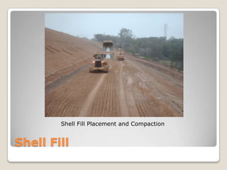
Construction Methods for Folsom Lake Dike ModificationPresented byMatthew D. MarksMagnus Pacific CorporationRoseville, California
OverviewProject Name - Dike 5 Embankment ModificationsEngineer/Designer - Bureau of Reclamation’s Safety of Dams (SOD) ProgramPrime Contractor – DD-M Crane and RiggingContract Value - $3,204,790Project Location - Located on the north shore of Folsom Reservoir near the intersection of Auburn-Folsom Boulevard and Eureka Road in Granite BayConstruction Schedule - Construction performed between September 2008 and February 2009
Area MapFOLSOM DAMFOLSOM LAKEDIKE 5SACRAMENTOAREA
Project SummaryScope of WorkProject involved the partial removal of the downstream face of the existing dike to construct new sand and gravel drains to control internal erosionChange OrdersNo major change orders; several quantity variations (overruns and underruns)By the Numbers40,000 CY excavation for existing downstream face3,500 CY excavation for new toe drain and out fall trenchInstalled 1,500 LF of 15” HDPE toe drain pipeInstalled 18,000 CY (28,000 TN) of fine filter (sand) and 2,500 CY (4,000 TN) of coarse filter (gravel)85,000 CY replacement of stockpiled and onsite borrow  soils
Scope of WorkSite preparations including recreation trail detourStripping top soil and excavation of downstream face from 2.25H:1V to 2H:1V slopeExcavation of toe drain and outfall trenchInstallation of toe drain and outfall piping and manholeToe drain backfill using coarse filter (gravel) and chimney drain using fine filter (sand)Reconstruct downstream face to 2.5H:1V slope using stockpiled and onsite borrow materialsReplace topsoil and site restoration
ScheduleBegan site preparations in mid August 2008Restricted to no heavy construction work until after Labor Day 2008Excavation work approximately 4 weeks at average rate of 3,000 CY per dayConcurrent placement of backfill materials including toe drain pipe, fine filter, coarse filter, and shell fill (average 100 TN coarse filter, 500 TN fine filter and 2,000 CY shell fill per day) over 3 to 4 month periodPerformed backfill and restoration work through first half of rainy seasonCompleted work in February 2009 (Contractual Completion Date in March 2009)
Embankment Fill Diagram~ EL. 4802.5 h1 v1 v2 h~ EL. 380Typical Embankment Fill Detail with Toe Drain
Toe Drain DiagramTypical Toe Drain Detail with Pipe
Conventional EquipmentExcavation & Hauling EquipmentPC 400 ExcavatorPC 300 ExcavatorCAT D9 Dozer (rock ripping)35 TN Articulated Haul Trucks (3 EA)Komatsu 450 Front End LoaderBackfill & Grading EquipmentCAT D6 Dozer (2 EA – GPS)CAT 815 CompactorCAT 140 Motor Grader48” Smooth Drum Roller (2 EA)
Specialized EquipmentMaterial Delivery SystemDrive Over End Dump Truck Unloader30 TN Surge Hopper/ConveyorTotal 70 TN Onsite Storage CapacityDirect Load Conveyor Trucks
Specialized EquipmentConveyor TrucksCAD (Conveyored Aggregate Delivery)Ability to place materials with accuracy and reduced wasteOutput approximately 250 to 500 TN / DY
Construction MaterialsShell FillOnsite Material (Decomposed Granite)Existing Dike EmbankmentBorrow Site within Folsom Reservoir3” MinusFine FilterImported MaterialClean Washed Sand3/8” Minus0 – 3% Passing No. 200 SieveCoarse FilterImported MaterialClean Washed Gravel1” Minus0 – 5% Passing No. 8 Sieve
Pre-ConstructionExisting Downstream Face
Pre-ConstructionExisting Top of Slope
Downstream Face ExcavationExcavated Face and Toe Drain (and view of Blanket Drain)
Toe Drain ExcavationToe Drain Excavation and Dewatering
Borrow Site ExcavationStockpiled Shell Fill in Folsom Reservoir
Toe DrainCompaction Testing Fine Filter Material
Toe DrainToe Drain Backfill with Fine and Coarse Filter Material
Shell FillShell Fill Placement on New Downstream Face
Shell FillShell Fill Placement and Compaction
Shell FillFine Filter and Shell Fill Placement
Shell FillShell Fill Grading (and Material Delivery System)
“The Big Picture”Fine Filter and Shell Fill Placement
Chimney DrainFine Filter Placement with Conveyor Truck
Chimney DrainFine Filter Placement (Non-compacted Loose Lift)
Chimney DrainFine Filter Placement Near Top of Downstream Face
Chimney DrainNew Blanket Drain on Upper Slope
FinishingExcavator Pulling Up Slope Near Top of Dike
FinishingTop of Chimney Drain and Shell Fill Placement
FinishingFinal Gravel Road on Crest of Dike
FinishingFinish Slope Grading and Topsoil (Dredge Tailings) Placement
Finishing Finished Slope (In Progress)
FinishingFinished Grade and Hydroseeding
Project HighlightsExcavation on face of dike and rock rippingExcavated with CAT D6 GPS Dozers pushing down slope; load out with Komatsu PC400 Excavator and Articulated Haul TrucksRock ripping in Borrow Site and Toe Drain using CAT D9 Dozer with rippers; intensely weathered granitic rock with uniaxial compressive strength ranging from about 330 to 850 psi  Placement of coarse and fine filter material without cross blending or wasteMaterial Delivery System replaced managing stockpiles and waste on groundConveyor Trucks allowed precise placement of coarse and fine filter with less than 1% wasteAchieved placement of 28,000 TN of fine filter without any failing tests for No. 200 sieve; material tested in place after compactionDetermination of proper compaction equipment and methodsTest sections on fine filter to determine proper equipment to minimize break down of materialMoisture conditioning fine filter and shell fill
Project Highlights (cont.)Managing site logistics, equipment access and coordinationHeavy equipment traffic patterns; one way traffic through work areasWorking in limited work space; steep slopesWeather related impacts and site storm water controlMost backfill work performed during rainy seasonInstallation and maintenance of site SWPPP controlsEffects of rain on site conditionsConstruction survey control for asbuilt and paymentUtilized GPS machine control on CAT D6 Dozer for excavation and backfill; achieved specified tolerancesMaintained full time surveyor onsite to survey asbuilt conditionsOrganization of data and volume calculationsHealth and SafetyCompleted the project with no injury or accidentsMinor incident involving propane powered fence post pounder; caught fire due to a manufacturer defect; product was recalled
QuestionsAny questions?DD-M Crane & Rigging2900 Main St., Suite 103Alameda, CA 94501(510) 769-8707(510) 769-8711 faxP.O. Box 520/160 River RdRio Vista, CA 94571(707) 374-2000(707) 374-2728 faxDenise Maurer - PresidentMagnus Pacific Corporation3001 Lava Ridge Court, Suite 240Roseville, CA 95661(916) 233-1139(916) 783-0215 faxLouay Owaidat - President

Marks Sess13 102309

  • 1.
    Construction Methods forFolsom Lake Dike ModificationPresented byMatthew D. MarksMagnus Pacific CorporationRoseville, California
  • 2.
    OverviewProject Name -Dike 5 Embankment ModificationsEngineer/Designer - Bureau of Reclamation’s Safety of Dams (SOD) ProgramPrime Contractor – DD-M Crane and RiggingContract Value - $3,204,790Project Location - Located on the north shore of Folsom Reservoir near the intersection of Auburn-Folsom Boulevard and Eureka Road in Granite BayConstruction Schedule - Construction performed between September 2008 and February 2009
  • 3.
    Area MapFOLSOM DAMFOLSOMLAKEDIKE 5SACRAMENTOAREA
  • 4.
    Project SummaryScope ofWorkProject involved the partial removal of the downstream face of the existing dike to construct new sand and gravel drains to control internal erosionChange OrdersNo major change orders; several quantity variations (overruns and underruns)By the Numbers40,000 CY excavation for existing downstream face3,500 CY excavation for new toe drain and out fall trenchInstalled 1,500 LF of 15” HDPE toe drain pipeInstalled 18,000 CY (28,000 TN) of fine filter (sand) and 2,500 CY (4,000 TN) of coarse filter (gravel)85,000 CY replacement of stockpiled and onsite borrow soils
  • 5.
    Scope of WorkSitepreparations including recreation trail detourStripping top soil and excavation of downstream face from 2.25H:1V to 2H:1V slopeExcavation of toe drain and outfall trenchInstallation of toe drain and outfall piping and manholeToe drain backfill using coarse filter (gravel) and chimney drain using fine filter (sand)Reconstruct downstream face to 2.5H:1V slope using stockpiled and onsite borrow materialsReplace topsoil and site restoration
  • 6.
    ScheduleBegan site preparationsin mid August 2008Restricted to no heavy construction work until after Labor Day 2008Excavation work approximately 4 weeks at average rate of 3,000 CY per dayConcurrent placement of backfill materials including toe drain pipe, fine filter, coarse filter, and shell fill (average 100 TN coarse filter, 500 TN fine filter and 2,000 CY shell fill per day) over 3 to 4 month periodPerformed backfill and restoration work through first half of rainy seasonCompleted work in February 2009 (Contractual Completion Date in March 2009)
  • 7.
    Embankment Fill Diagram~EL. 4802.5 h1 v1 v2 h~ EL. 380Typical Embankment Fill Detail with Toe Drain
  • 8.
    Toe Drain DiagramTypicalToe Drain Detail with Pipe
  • 9.
    Conventional EquipmentExcavation &Hauling EquipmentPC 400 ExcavatorPC 300 ExcavatorCAT D9 Dozer (rock ripping)35 TN Articulated Haul Trucks (3 EA)Komatsu 450 Front End LoaderBackfill & Grading EquipmentCAT D6 Dozer (2 EA – GPS)CAT 815 CompactorCAT 140 Motor Grader48” Smooth Drum Roller (2 EA)
  • 10.
    Specialized EquipmentMaterial DeliverySystemDrive Over End Dump Truck Unloader30 TN Surge Hopper/ConveyorTotal 70 TN Onsite Storage CapacityDirect Load Conveyor Trucks
  • 11.
    Specialized EquipmentConveyor TrucksCAD(Conveyored Aggregate Delivery)Ability to place materials with accuracy and reduced wasteOutput approximately 250 to 500 TN / DY
  • 12.
    Construction MaterialsShell FillOnsiteMaterial (Decomposed Granite)Existing Dike EmbankmentBorrow Site within Folsom Reservoir3” MinusFine FilterImported MaterialClean Washed Sand3/8” Minus0 – 3% Passing No. 200 SieveCoarse FilterImported MaterialClean Washed Gravel1” Minus0 – 5% Passing No. 8 Sieve
  • 13.
  • 14.
  • 15.
    Downstream Face ExcavationExcavatedFace and Toe Drain (and view of Blanket Drain)
  • 16.
    Toe Drain ExcavationToeDrain Excavation and Dewatering
  • 17.
    Borrow Site ExcavationStockpiledShell Fill in Folsom Reservoir
  • 18.
    Toe DrainCompaction TestingFine Filter Material
  • 19.
    Toe DrainToe DrainBackfill with Fine and Coarse Filter Material
  • 20.
    Shell FillShell FillPlacement on New Downstream Face
  • 21.
    Shell FillShell FillPlacement and Compaction
  • 22.
    Shell FillFine Filterand Shell Fill Placement
  • 23.
    Shell FillShell FillGrading (and Material Delivery System)
  • 24.
    “The Big Picture”FineFilter and Shell Fill Placement
  • 25.
    Chimney DrainFine FilterPlacement with Conveyor Truck
  • 26.
    Chimney DrainFine FilterPlacement (Non-compacted Loose Lift)
  • 27.
    Chimney DrainFine FilterPlacement Near Top of Downstream Face
  • 28.
    Chimney DrainNew BlanketDrain on Upper Slope
  • 29.
    FinishingExcavator Pulling UpSlope Near Top of Dike
  • 30.
    FinishingTop of ChimneyDrain and Shell Fill Placement
  • 31.
  • 32.
    FinishingFinish Slope Gradingand Topsoil (Dredge Tailings) Placement
  • 33.
  • 34.
  • 35.
    Project HighlightsExcavation onface of dike and rock rippingExcavated with CAT D6 GPS Dozers pushing down slope; load out with Komatsu PC400 Excavator and Articulated Haul TrucksRock ripping in Borrow Site and Toe Drain using CAT D9 Dozer with rippers; intensely weathered granitic rock with uniaxial compressive strength ranging from about 330 to 850 psi Placement of coarse and fine filter material without cross blending or wasteMaterial Delivery System replaced managing stockpiles and waste on groundConveyor Trucks allowed precise placement of coarse and fine filter with less than 1% wasteAchieved placement of 28,000 TN of fine filter without any failing tests for No. 200 sieve; material tested in place after compactionDetermination of proper compaction equipment and methodsTest sections on fine filter to determine proper equipment to minimize break down of materialMoisture conditioning fine filter and shell fill
  • 36.
    Project Highlights (cont.)Managingsite logistics, equipment access and coordinationHeavy equipment traffic patterns; one way traffic through work areasWorking in limited work space; steep slopesWeather related impacts and site storm water controlMost backfill work performed during rainy seasonInstallation and maintenance of site SWPPP controlsEffects of rain on site conditionsConstruction survey control for asbuilt and paymentUtilized GPS machine control on CAT D6 Dozer for excavation and backfill; achieved specified tolerancesMaintained full time surveyor onsite to survey asbuilt conditionsOrganization of data and volume calculationsHealth and SafetyCompleted the project with no injury or accidentsMinor incident involving propane powered fence post pounder; caught fire due to a manufacturer defect; product was recalled
  • 37.
    QuestionsAny questions?DD-M Crane& Rigging2900 Main St., Suite 103Alameda, CA 94501(510) 769-8707(510) 769-8711 faxP.O. Box 520/160 River RdRio Vista, CA 94571(707) 374-2000(707) 374-2728 faxDenise Maurer - PresidentMagnus Pacific Corporation3001 Lava Ridge Court, Suite 240Roseville, CA 95661(916) 233-1139(916) 783-0215 faxLouay Owaidat - President