Download to read offline
![Make: Arduino Bots and Gadgets
by Kimmo and Tero Karvinen
Copyright © 2011 O’Reilly Media, Inc. All rights reserved.
Printed in Canada.
Published by O’Reilly Media, Inc., 1005 Gravenstein Highway North, Sebastopol, CA 95472.
O’Reilly Media books may be purchased for educational, business, or sales promotional use. Online editions are also avail-
able for most titles (my.safaribooksonline.com). For more information, contact our corporate/institutional sales department:
800-998-9938 or corporate@oreilly.com.
Development Editors: Brian Jepson and Brian Sawyer
Production Editor: Holly Bauer
Technical Editor: Joe Saavedra
Copyeditor: Rachel Monaghan
Proofreader: Jennifer Knight
Translator: Marko Tandefelt
Indexer: Ellen Troutman Zaig
Cover Designer: Mark Paglietti
Interior Designer: Ron Bilodeau
Illustrator/Photographer: Kimmo Karvinen
Cover Photographer: Kimmo Karvinen
Software Architect: Tero Karvinen
Print History:
March 2011: First Edition.
The O’Reilly logo is a registered trademark of O’Reilly Media, Inc. Many of the designations used by manufacturers and sellers
to distinguish their products are claimed as trademarks. Where those designations appear in this book, and O’Reilly Media,
Inc., was aware of a trademark claim, the designations have been printed in caps or initial caps.
Important Message to Our Readers: The technologies discussed in this publication, the limitations on these technologies
that technology and content owners seek to impose, and the laws actually limiting the use of these technologies are con-
stantly changing. Thus, some of the projects described in this publication may not work, may cause unintended harm to
systems on which they are used, or may not be consistent with current laws or applicable user agreements.
Your safety is your own responsibility, including proper use of equipment and safety gear, and determining whether you
have adequate skill and experience. Electricity and other resources used for these projects are dangerous unless used prop-
erly and with adequate precautions, including safety gear. These projects are not intended for use by children. While every
precaution has been taken in the preparation of this book,
O’Reilly Media, Inc. and the authors assume no responsibility for errors or omissions. Use of the instructions and suggestions
in Make: Arduino: Bots and Gadgets is at your own risk. O’Reilly Media, Inc. and the authors disclaim all responsibility for any
resulting damage, injury, or expense. It is your responsibility to make sure that your activities comply with applicable laws,
including copyright.
This book uses Otabind™, a durable and flexible lay-flat binding.
ISBN: 978-1-449-38971-0
[TI]
www.engbookspdf.com](https://image.slidesharecdn.com/makearduinobotsandgadgetslearningbydiscoverybykimmoandterokarvinen-1-201218032819/75/Arduino-Crea-bots-y-gadgets-Arduino-aprendiendo-mediante-el-descubrimiento-de-kimmo-y-tero-karvinen-4-2048.jpg)


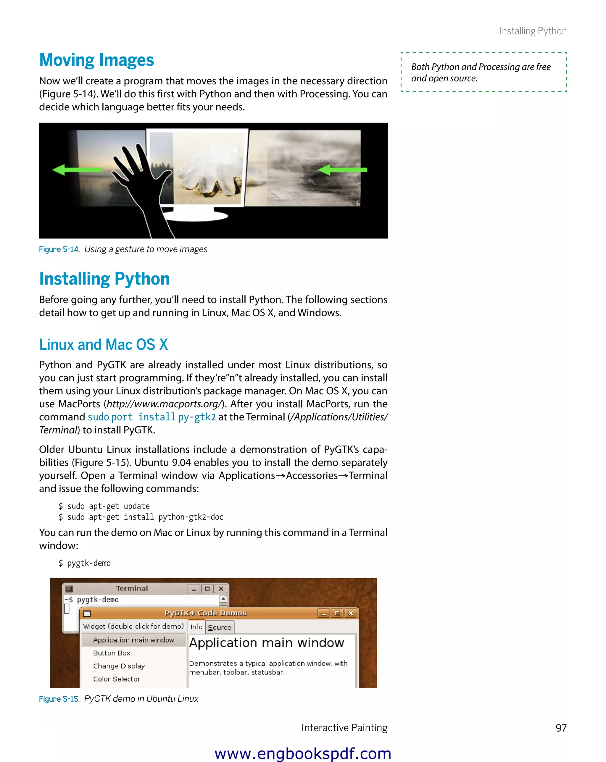
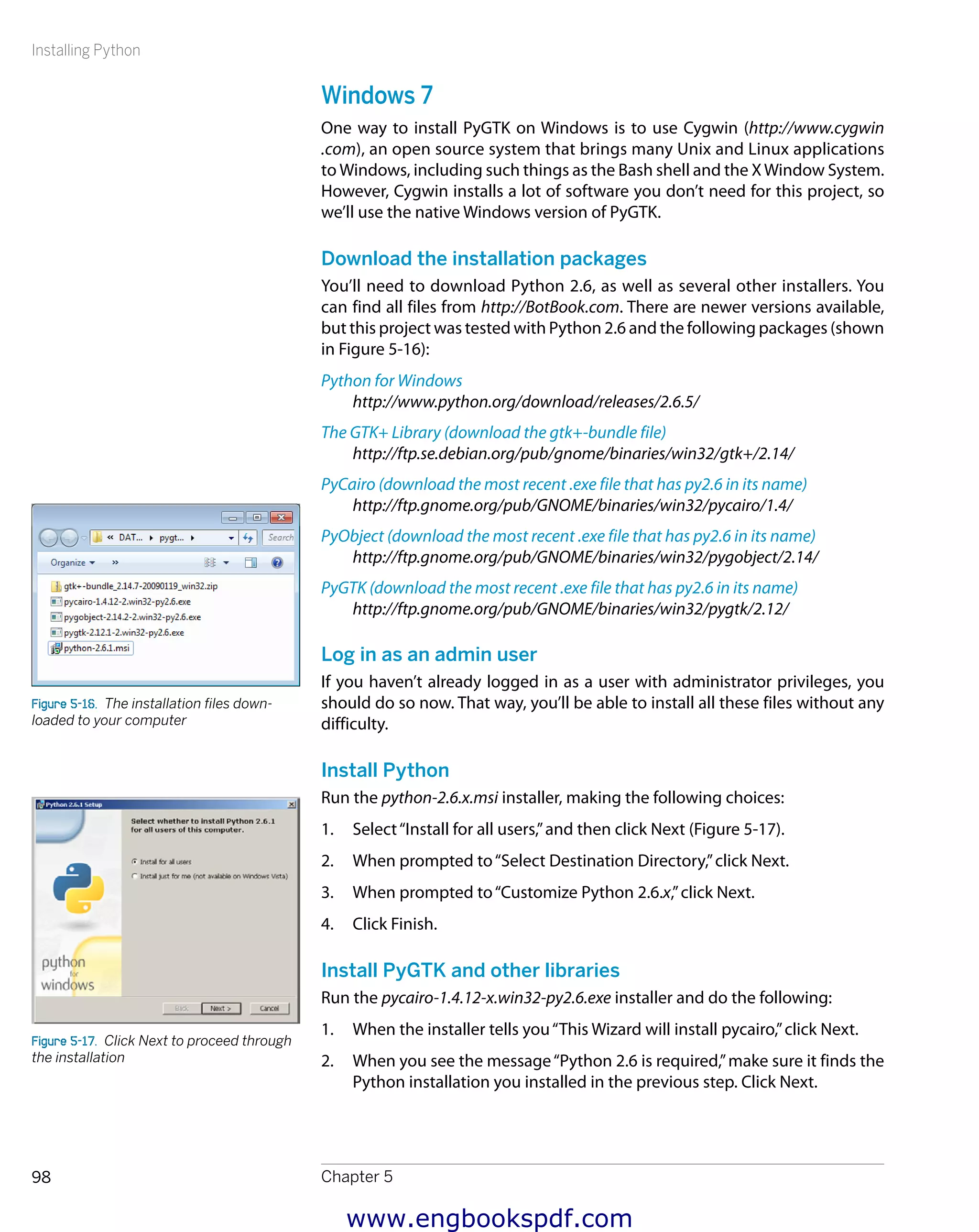
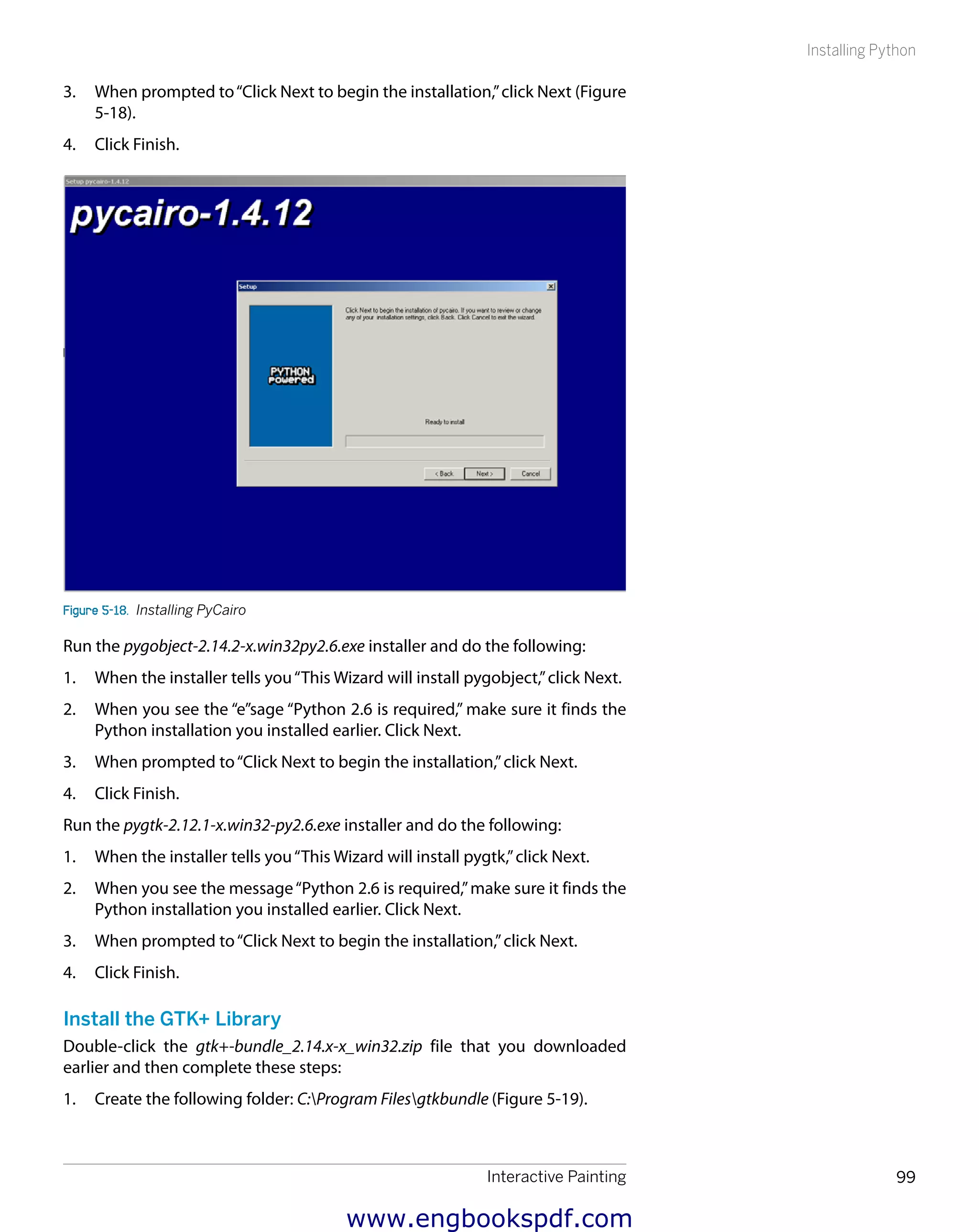
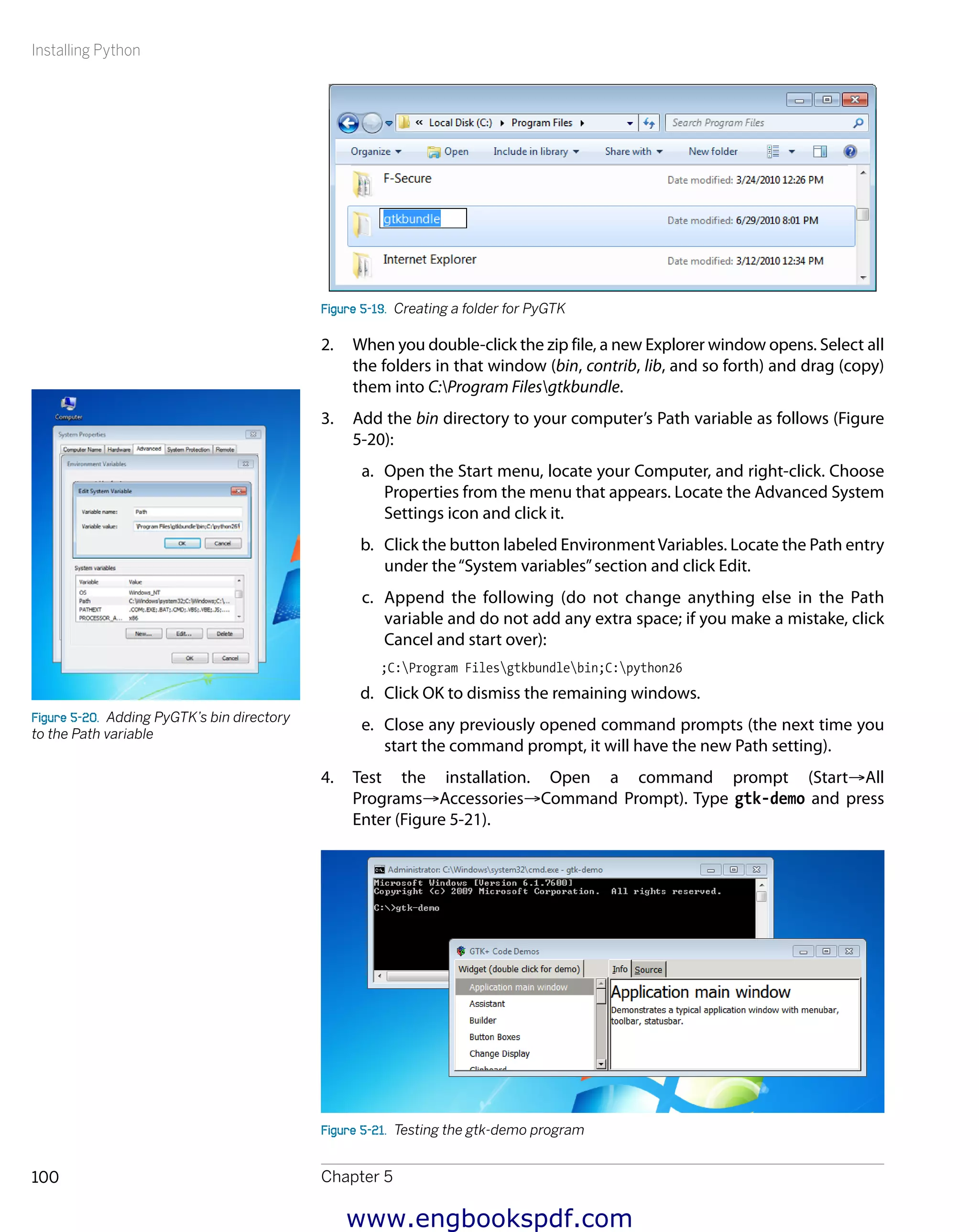
![Changing Images with Button Control
Chapter 5112
#!/usr/bin/env python
# multipleImages.py - Display image in a window.
# (c) Kimmo Karvinen & Tero Karvinen http://BotBook.com
import gtk, os
dir="data" 1
pixbufs=[]
image=None
pos=0
def loadImages():
for file in os.listdir(dir): 2
filePath=os.path.join(dir, file) 3
pix=gtk.gdk.pixbuf_new_from_file(filePath) 4
pixbufs.append(pix) 5
print("Loaded image "+filePath)
def keyEvent(widget, event): 6
global pos
key = gtk.gdk.keyval_name(event.keyval) 7
if key=="space" or key=="Page_Down": 8
pos+=1
image.set_from_pixbuf(pixbufs[pos])
elif key=="b" or key=="Page_Up":
pos-=1
image.set_from_pixbuf(pixbufs[pos])
else:
print("Key "+key+" was pressed") 9
def main():
global image
window = gtk.Window()
window.connect("destroy", gtk.main_quit) bk
window.connect("key-press-event", keyEvent) bl
image=gtk.Image()
window.add(image) bm
loadImages()
image.set_from_pixbuf(pixbufs[pos])
window.show_all()
gtk.main() bn
if __name__=="__main__":
main()
This program is similar to the single-image viewer, so we’ll concentrate on the
differences. Let’s look at each piece of the code.
1 Declare global variables in the beginning of the program, outside of all
functions. Images are read from the dir directory and will later be added
to the pixbufs list. The pos variable shows the order of the picture
shown. We’ll fill in the image shown in a window (image) later.
2 List the contents of our image directory, which we defined previously
as data. With this variable value, the command will be equivalent to
os.listdir("data"), which will return a list, such as ['foo.jpg',
'image1.jpg', 'sulautetut.svg']. This list will be used in the for
loop, which would be equivalent to something like for file in
['foo.jpg', 'image1.jpg', 'sulautetut.svg'].
You can download these images
from http://BotBook.com. You might
need to install the librsvg library to
use this example with SVN images.
On Mac OS X with MacPorts, use
sudo port install librsvg. On
Ubuntu Linux, use sudo apt-get
install python-rsvg. On Win-
dows, it may be a bit more compli
cated (see http://librsvg.source-
forge.net/ for more information
about this library).
www.engbookspdf.com](https://image.slidesharecdn.com/makearduinobotsandgadgetslearningbydiscoverybykimmoandterokarvinen-1-201218032819/75/Arduino-Crea-bots-y-gadgets-Arduino-aprendiendo-mediante-el-descubrimiento-de-kimmo-y-tero-karvinen-128-2048.jpg)
![Interactive Painting 113
Gesture Controlled Painting in Full Screen
3 Combine each file with its path, using the os.path.join() function.
4 Load each file into a new pixel buffer (of type Pixbuf) called pix. The
pixbuf_new_from_file() makes our life easier by creating a new
Pixbuf object and loading an image from a file into it at the same time.
Pixbuf objects are meant for handling images within the computer
memory. They cannot be displayed directly. We’ll have to copy data from
the Pixbuf object into an image widget to display it.
5 Append our image to the end of the list pixbufs. The length of the list
grows by one. Now the last member of the list is the same as pix. When
the loop has been executed with all the values, the program returns to
the point in main() at which loadImages was called.
6 React to two types of events: clicking the window close (X) button and
pressing the keys. Pressing a key calls the keyEvent() function from the
GTK main loop. This function is passed in the widget that caused the
event as well as in the event itself.
7 Read the name of the key press from the event that was passed in.
8 If the key pressed is a space bar or Page Down, move one image for-
ward and show the corresponding Pixbuf object in the widget image.
The first position in the list is numbered 0. For example, if we are in
the second image, the value will be equivalent to image.set_from_
pixbuf(pixbufs[1]), which is the picture loaded from the directory
image1.jpg. The landscape will appear immediately within the image
widget, which fills the window. Moving backward works the same way.
9 Display other keys in the console for informational purposes.
bk If the user closes the window, the program quits.
bl Detect any key presses within the window when the window is active.
When a key press event occurs, call the keyEvent() function. GTK auto-
matically sends the widget that received the event, as well as the event
itself, as parameters.
bm Add the first picture in the image list to the image widget shown in the
window. Here, the value of variable pos is 0 (the first image in the list).
bn Start the main loop of the GTK library, where the program will spend the
rest of its execution time while waiting for events.
Gesture-Controlled Painting in Full Screen
Now’s the time to combine all the components we have built into a painting a
user can control by waving her hand in front of it.
#!/usr/bin/env python
# handWaveFull.py - Choose full screen image by waving hand.
# (c) Kimmo Karvinen & Tero Karvinen http://BotBook.com
import gtk, os, serial, gobject
www.engbookspdf.com](https://image.slidesharecdn.com/makearduinobotsandgadgetslearningbydiscoverybykimmoandterokarvinen-1-201218032819/75/Arduino-Crea-bots-y-gadgets-Arduino-aprendiendo-mediante-el-descubrimiento-de-kimmo-y-tero-karvinen-129-2048.jpg)
![Gesture Controlled Painting in Full Screen
Chapter 5114
# Global variables
dir="data"
pixbufs=[]
image=None
bg=None
pos=0
ser=None
# Pixbuf manipulation
def fitRect(thing, box):
# scale
scaleX=float(box.width)/thing.width
scaleY=float(box.height)/thing.height
scale=min(scaleY, scaleX)
thing.width=scale*thing.width
thing.height=scale*thing.height
# center
thing.x=box.width/2-thing.width/2
thing.y=box.height/2-thing.height/2
return thing
def scaleToBg(pix, bg):
fit=fitRect(
gtk.gdk.Rectangle(0,0, pix.get_width(), pix.get_height()),
gtk.gdk.Rectangle(0,0, bg.get_width(), bg.get_height())
)
scaled=pix.scale_simple(fit.width, fit.height, gtk.gdk.INTERP_BILINEAR)
ret=bg.copy()
scaled.copy_area(
src_x=0, src_y=0,
width=fit.width, height=fit.height,
dest_pixbuf=ret,
dest_x=fit.x, dest_y=fit.y
)
return ret
def newPix(width, height, color=0x000000ff):
pix=gtk.gdk.Pixbuf(gtk.gdk.COLORSPACE_RGB, True, 8, width , height)
pix.fill(color)
return pix
# File reading
def loadImages():
global pixbufs
for file in os.listdir(dir):
filePath=os.path.join(dir, file)
pix=gtk.gdk.pixbuf_new_from_file(filePath)
pix=scaleToBg(pix, bg)
pixbufs.append(pix)
print("Loaded image "+filePath)
# Controls
def go(relativePos): 1
global pos
pos+=relativePos
www.engbookspdf.com](https://image.slidesharecdn.com/makearduinobotsandgadgetslearningbydiscoverybykimmoandterokarvinen-1-201218032819/75/Arduino-Crea-bots-y-gadgets-Arduino-aprendiendo-mediante-el-descubrimiento-de-kimmo-y-tero-karvinen-130-2048.jpg)
![Interactive Painting 115
Gesture Controlled Painting in Full Screen
last=len(pixbufs)-1 2
if pos<0:
pos=last
elif pos>last:
pos=0
image.set_from_pixbuf(pixbufs[pos])
def keyEvent(widget, event):
global pos, image
key = gtk.gdk.keyval_name(event.keyval)
if key=="space" or key=="Page_Down":
go(1) 3
elif key=="b" or key=="Page_Up":
go(-1)
elif key=="q" or key=="F5":
gtk.main_quit()
else:
print("Key "+key+" was pressed")
def pollSerial():
cmd=ser.read(size=1)
print("Serial port read: "%s"" % cmd)
if cmd=="F":
go(1)
elif cmd=="B":
go(-1)
return True
# Main
def main():
global bg, image, ser
bg=newPix(gtk.gdk.screen_width(), gtk.gdk.screen_height())
loadImages()
image=gtk.image_new_from_pixbuf(pixbufs[pos])
ser = serial.Serial('/dev/ttyUSB1', 9600, timeout=0 4)
gobject.timeout_add(100, pollSerial)
window = gtk.Window()
window.connect("destroy", gtk.main_quit)
window.connect("key-press-event", keyEvent)
window.fullscreen()
window.add(image)
window.show_all()
gtk.main()
if __name__ == "__main__":
main()
This example brings together the previous Python examples you’ve seen in
this chapter: keyboard control, reading the serial port, and stretching images
to full-screen mode.
This program halts if the serial port is not found. If you want to test the pro-
gram simply from the keyboard without Arduino connected to the serial port,
comment out these lines by inserting # at the beginning of each:
ser = serial.Serial('/dev/ttyUSB1', 9600)
gobject.timeout_add(100, pollSerial)
This program expects to talk to an
Arduino that’s running the sketch
listed earlier in this chapter (see the
section “Determining Direction with
the Final Sensor”).
www.engbookspdf.com](https://image.slidesharecdn.com/makearduinobotsandgadgetslearningbydiscoverybykimmoandterokarvinen-1-201218032819/75/Arduino-Crea-bots-y-gadgets-Arduino-aprendiendo-mediante-el-descubrimiento-de-kimmo-y-tero-karvinen-131-2048.jpg)
![Animating the Sliding Image
Chapter 5116
Let’s have a look at some of the code:
1 Because the images can be rotated using both the keyboard and mes-
sages from the serial port, the go() function handles both.
2 In the previous example, you might have noticed you get an error if
you try to go beyond the last image. This code takes the user back to
the beginning if she tries to go past the end, and vice versa. If the user
moves backward from the first image (pos<0), the program moves to the
last image (pos=last). If the user moves past the last image (last<pos),
she returns to the first image. The first index of the array of images is 0.
The last cell is the length of the list minus one. For example, in a list with
three images, the indexes are 0, 1, and 2.
3 Calling go() with an argument of 1 will move to the next image; go(-1)
moves to the previous image.
4 Setting timeout to 0 prevents ser.read() from blocking (waiting
forever for input from the Arduino). This way, you’ll be able to use the
keyboard and Arduino for input simultaneously.
Now the program is missing only some eye candy (animations). For now, run
it with an Arduino connected (while running the interactivePaintingSensor
sketch from the section “Determining Direction with the Final Sensor”), and
try to choose images by waving your hand in the air.
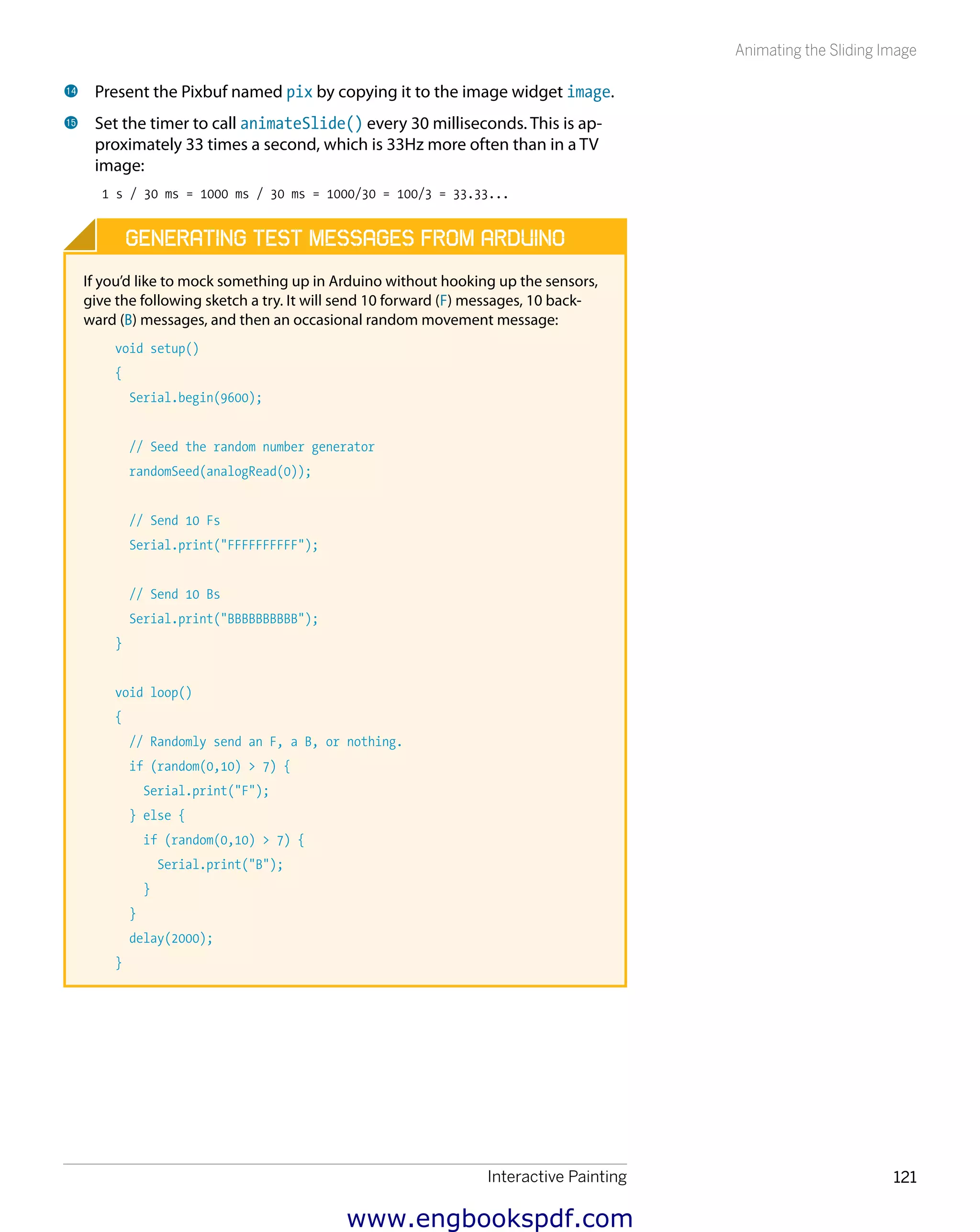
Animating the Sliding Image
As the icing on the cake, we’ll add an animation to the painting. Images will
slide to their place. Our program is ready.
All functionality from the previous exercises is included in this version. Images
spread to full screen, both the serial port and the keyboard are used for con-
trolling behavior, and images are loaded from a folder. The images can be in
many different formats, such as JPG, SVG, GIF, or PNG.
This is also an example of a timed gobject.add_timeout() animation. We ask
the timer to call for our function, for example, 10 times a second, and during
each call we draw a new animation frame.
#!/usr/bin/env python
# interactivePainting.py - Choose full screen image by waving hand.
# (c) Kimmo Karvinen & Tero Karvinen http://BotBook.com
import gtk, os, serial, gobject
# Global variables
dir="data"
pixbufs=[]
image=None
bg=None
pos=0
ser=None
reel=None
x=0
Be sure to change /dev/ttyUSB1 to
the filename of the serial port your
Arduino is connected to.
www.engbookspdf.com](https://image.slidesharecdn.com/makearduinobotsandgadgetslearningbydiscoverybykimmoandterokarvinen-1-201218032819/75/Arduino-Crea-bots-y-gadgets-Arduino-aprendiendo-mediante-el-descubrimiento-de-kimmo-y-tero-karvinen-132-2048.jpg)
![Animating the Sliding Image
Chapter 5118
src_x=x, src_y=0,
width=width, height=pix.get_height(),
dest_pixbuf=buf, dest_x=0, dest_y=0)
return buf
# File reading
def loadImages():
global pixbufs
for file in os.listdir(dir):
filePath=os.path.join(dir, file)
pix=gtk.gdk.pixbuf_new_from_file(filePath)
pix=scaleToBg(pix, bg)
pixbufs.append(pix)
print("Loaded image "+filePath)
# Controls
def go(relativePos):
global pos, reel, x, speed
last=len(pixbufs)-1
if pos<0:
pos=last
elif pos>last:
pos=0
if 0<relativePos:
print("Next")
if pos==last:
right=0
else:
right=pos+1 7
reel=catenate(pixbufs[pos], pixbufs[right])
x=0 8
speed=60
if relativePos<0:
print("prev")
if pos==0:
left=last
else:
left=pos-1
reel=catenate(pixbufs[left], pixbufs[pos])
x=w
speed=-60
print("pos == "+str(pos))
pos+=relativePos 9
def animateSlide():
global reel, x, speed
if speed!=0: bk
x+=speed bl
if x>=w or x<=0: bm
speed=0
print x, reel
pix=getBox(reel, x, w) bn
image.set_from_pixbuf(pix) bo
return True
def keyEvent(widget, event):
global pos, image
key = gtk.gdk.keyval_name(event.keyval)
www.engbookspdf.com](https://image.slidesharecdn.com/makearduinobotsandgadgetslearningbydiscoverybykimmoandterokarvinen-1-201218032819/75/Arduino-Crea-bots-y-gadgets-Arduino-aprendiendo-mediante-el-descubrimiento-de-kimmo-y-tero-karvinen-134-2048.jpg)
![Interactive Painting 119
Animating the Sliding Image
if key=="space" or key=="Page_Down":
go(1)
elif key=="b" or key=="Page_Up":
go(-1)
elif key=="q" or key=="F5" or key=="ESC":
gtk.main_quit()
else:
print("Key "+key+" was pressed")
def pollSerial():
if ser.inWaiting()<=0:
#print("No data waiting in serial buffer.")
return True # call again later
cmd=ser.read(size=1)
print("Serial port read: "%s"" % cmd)
if cmd=="F":
go(1)
elif cmd=="B":
go(-1)
return True
# Main
def main():
global bg, image, ser, w
w=gtk.gdk.screen_width()
h=gtk.gdk.screen_height()
window = gtk.Window()
window.connect("destroy", gtk.main_quit)
window.connect("key-press-event", keyEvent)
window.fullscreen()
bg=newPix(w, h)
loadImages()
image=gtk.image_new_from_pixbuf(pixbufs[pos])
ser = serial.Serial('/dev/ttyUSB0’, 9600, timeout=0)
gobject.timeout_add(100, pollSerial)
gobject.timeout_add(30, animateSlide) bp
window.add(image)
window.show_all()
gtk.main()
if __name__ == "__main__":
main()
Let’s look at the key parts of the code:
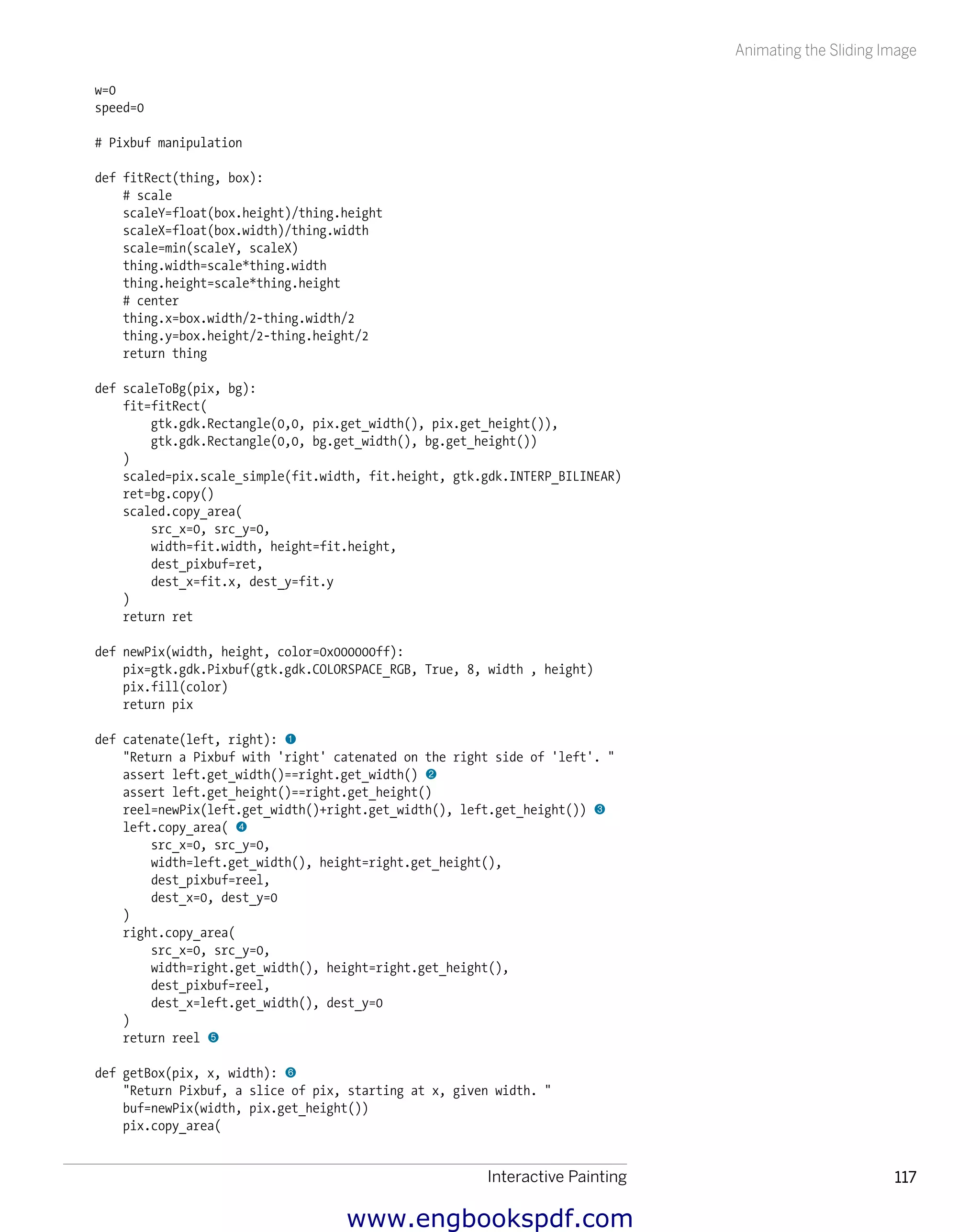
1 Join two images together, side by side, for the animation.
2 The images to be joined must be exactly the same height and width. If
we accidentally try the program with different image sizes, we want to
know about this mistake immediately. The assert command interrupts
the execution of the program with an error message, if the condition fol-
lowing it is not true. If assert interrupts the execution of the program, it
means there is a problem.
3 Create a new Pixbuf image buffer, onto which both images are copied.
Be sure to change /dev/ttyUSB1 to
the filename of the serial port your
Arduino is connected to.
www.engbookspdf.com](https://image.slidesharecdn.com/makearduinobotsandgadgetslearningbydiscoverybykimmoandterokarvinen-1-201218032819/75/Arduino-Crea-bots-y-gadgets-Arduino-aprendiendo-mediante-el-descubrimiento-de-kimmo-y-tero-karvinen-135-2048.jpg)
![Animating the Sliding Image
Chapter 5120
This is necessary because with the copy_area() method, we can draw
only to the area that already exists within the source image. We use the
newly defined newPix() function, and we will store the buffer under the
name reel.
4 Copy the left-side image called left to its place in image reel. We use
the copy_area() method from the left-side image. Let’s copy starting
from the upper-left corner of the image left (0,0) for the whole width
and height (get_width()…). Let’s set the image “reel”(dest_pixbuf) to
the upper-left corner (0, 0). Then copy the right-side image the same way.
5 Finally, the function returns the image reel, which is a combination
of images left and right. This function does not relate to the global
function reel of the same name. Here, reel is a local variable, which will
become available for the caller as a value returned by the function.
6 This function takes a slice of the image. It creates a new Pixbuf image
buffer with newPix(). Then it copies an area of the requested size. Since
the copy_area() method has so many parameters, we have used an
option available in Python of marking the name of the parameter in the
call. The number of parameters in the copy_area() method is a good
reason to separate getBox() into its own function.
7 This makes a reel for the animation that has the current image on the
left and the next picture on the right. The number of the current image is
pos, so the current image buffer is pixbufs[pos].
8 For the animation, the current position is on the left side of the reel, x=0.
This sets the update speed as 60 pixels to the right. The animateSlide()
function uses these values.
9 Update the current position. Here, the relativePos parameter is 1, as
defined in the go(1) function call.
bk The image is updated and moved only if speed (speed) has been defined
for it.
animateSlide() always returns true, which allows the timer to call it again no
matter what happens within it.
bl Move the left side position forward as defined by speed. When moving
the image backward, speed is negative.
bm If the program has already moved to another image, this stops the move-
ment. When moving the image backward (to the left), we will face the
left side of the image reel, x<=0. When moving the image forward (to
the right), we will face the center point of the image reel, x>=w. Then
the right side of the image shown will be exactly on the right side of the
image reel.
bn Pick a screenwide segment from the image reel, beginning at position
x. We have previously stored the width of the screen to the variable w. All
images have been scaled to be as wide as the screen.
www.engbookspdf.com](https://image.slidesharecdn.com/makearduinobotsandgadgetslearningbydiscoverybykimmoandterokarvinen-1-201218032819/75/Arduino-Crea-bots-y-gadgets-Arduino-aprendiendo-mediante-el-descubrimiento-de-kimmo-y-tero-karvinen-136-2048.jpg)
![Connecting Arduino with Processing
Chapter 5122
Connecting Arduino with Processing
Processing (http://processing.org/) is an open source language for creating ani-
mations, images, and interactive software. You can download the Processing
integrated development environment from http://processing.org/download/.
One of the first things you might notice is that it looks just like Arduino (see
Figure 5-24). This is because Arduino and Processing are sister projects that
both embrace the goals of simplicity, open source, and accessibility to a wide
audience.
Although Processing and Arduino are different programming languages, they
share enough similarities that it is easy to switch between them.
Just as with Arduino, Processing programs are known as sketches. The following
simple sketch reads the serial port and displays the output in the Processing
window. To run it, click the leftmost button (Run).
import processing.serial.*; 1
// A serial port that we use to talk to Arduino.
Serial myPort; 2
// The Processing setup method that’s run once
void setup() { 7
size(320, 320); // create a window 4
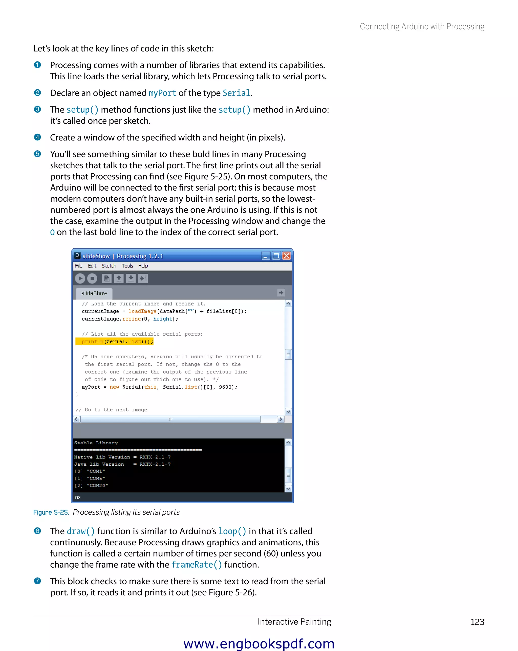
// List all the available serial ports: 5
println(Serial.list());
/* On some computers, Arduino will usually be connected to
the first serial port. If not, change the 0 to the
correct one (examine the output of the previous line
of code to figure out which one to use). */
myPort = new Serial(this, Serial.list()[0], 9600);
}
/* The draw() method is called up to 60 times a second
unless you change the frame rate of Processing.
Normally, it is used to update the graphics onscreen,
but we're just polling the serial port here.
*/
void draw() { 6
// Put up a black background.
background(0);
// Read the serial port.
if (myPort.available() > 0) { 7
char inByte = myPort.readChar();
print(inByte); // Displays the character that was read
}
}
Figure 5-24. The Processing integrated
development environment
Please note the code listed in bold,
because it contains important infor-
mation about configuring Processing
to talk to the right serial port.
www.engbookspdf.com](https://image.slidesharecdn.com/makearduinobotsandgadgetslearningbydiscoverybykimmoandterokarvinen-1-201218032819/75/Arduino-Crea-bots-y-gadgets-Arduino-aprendiendo-mediante-el-descubrimiento-de-kimmo-y-tero-karvinen-138-2048.jpg)
![Interactive Painting 125
Processing Code for the Painting
int slideOffset; 4
// All the image files found in this sketch’s data/ directory.
String[] fileList; 5
// A serial port that we use to talk to Arduino.
Serial myPort;
// This class is used to filter the list of files in the data directory
// so that the list includes only images.
class FilterImages implements java.io.FilenameFilter { 6
public boolean accept(File dir, String fname) {
String[] extensions = {".png", ".jpeg", ".gif", ".tga", ".jpg"};
// Don’t accept a file unless it has one of the specified extensions
for (int i = 0; i < extensions.length; i++) {
if (fname.toLowerCase().endsWith( extensions[i])) {
return true;
}
}
return false;
}
}
// This loads the filenames into the fileList
void loadFileNames() { 7
java.io.File dir = new java.io.File(dataPath(""));
fileList = dir.list(new FilterImages());
}
// The Processing setup method that’s run once
void setup() {
size(screen.width, screen.height); // Go fullscreen
loadFileNames(); // Load the filenames
/* This centers images on the screen. To work correctly with
this mode, we'll be using image coordinates from the center
of the screen (1/2 of the screen height and width) .
*/
imageMode(CENTER); 8
// Load the current image and resize it.
currentImage = loadImage(dataPath("") + fileList[0]); 9
currentImage.resize(0, height);
println(Serial.list()); bk
myPort = new Serial(this, Serial.list()[0], 9600); bl
}
// Go to the next image
void advanceSlide() { bm
imgIndex++; // go to the next image
if (imgIndex >= fileList.length) { // make sure we're within bounds
imgIndex = 0;
}
www.engbookspdf.com](https://image.slidesharecdn.com/makearduinobotsandgadgetslearningbydiscoverybykimmoandterokarvinen-1-201218032819/75/Arduino-Crea-bots-y-gadgets-Arduino-aprendiendo-mediante-el-descubrimiento-de-kimmo-y-tero-karvinen-141-2048.jpg)
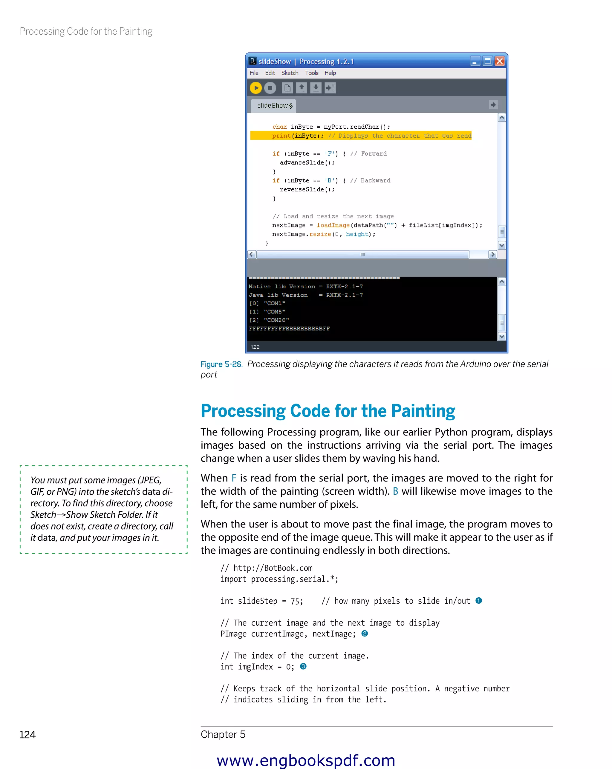
![Processing Code for the Painting
Chapter 5126
slideOffset = width; // Start sliding in from the right
}
void reverseSlide() {
imgIndex--; // go to the previous image
if (imgIndex < 0) { // make sure we're within bounds
imgIndex = fileList.length - 1;
}
slideOffset = width * - 1; // Start sliding in from the left
}
void draw() {
// Put up a black background and display the current image.
background(0);
image(currentImage, width/2, height/2); bn
// Is the image supposed to be sliding?
if (slideOffset != 0) { bo
// Load the next image at the specified offset.
image(nextImage, slideOffset + width/2, height/2);
if (slideOffset > 0) { // Slide from the right (next) bp
slideOffset -= slideStep;
if (slideOffset < 0) {
slideOffset = 0;
}
}
if (slideOffset < 0) { // Slide from the left (previous)
slideOffset += slideStep;
if (slideOffset > 0) {
slideOffset = 0;
}
}
if (slideOffset == 0) { bq
currentImage = nextImage;
}
}
else {
// If we're not sliding, read the serial port.
if (myPort.available() > 0) {
char inByte = myPort.readChar();
print(inByte); // Displays the character that was read
if (inByte == 'F') { // Forward
advanceSlide(); br
}
if (inByte == 'B') { // Backward
reverseSlide();
}
// Load and resize the next image
nextImage = loadImage(dataPath("") + fileList[imgIndex]); bs
nextImage.resize(0, height);
}
}
}
www.engbookspdf.com](https://image.slidesharecdn.com/makearduinobotsandgadgetslearningbydiscoverybykimmoandterokarvinen-1-201218032819/75/Arduino-Crea-bots-y-gadgets-Arduino-aprendiendo-mediante-el-descubrimiento-de-kimmo-y-tero-karvinen-142-2048.jpg)


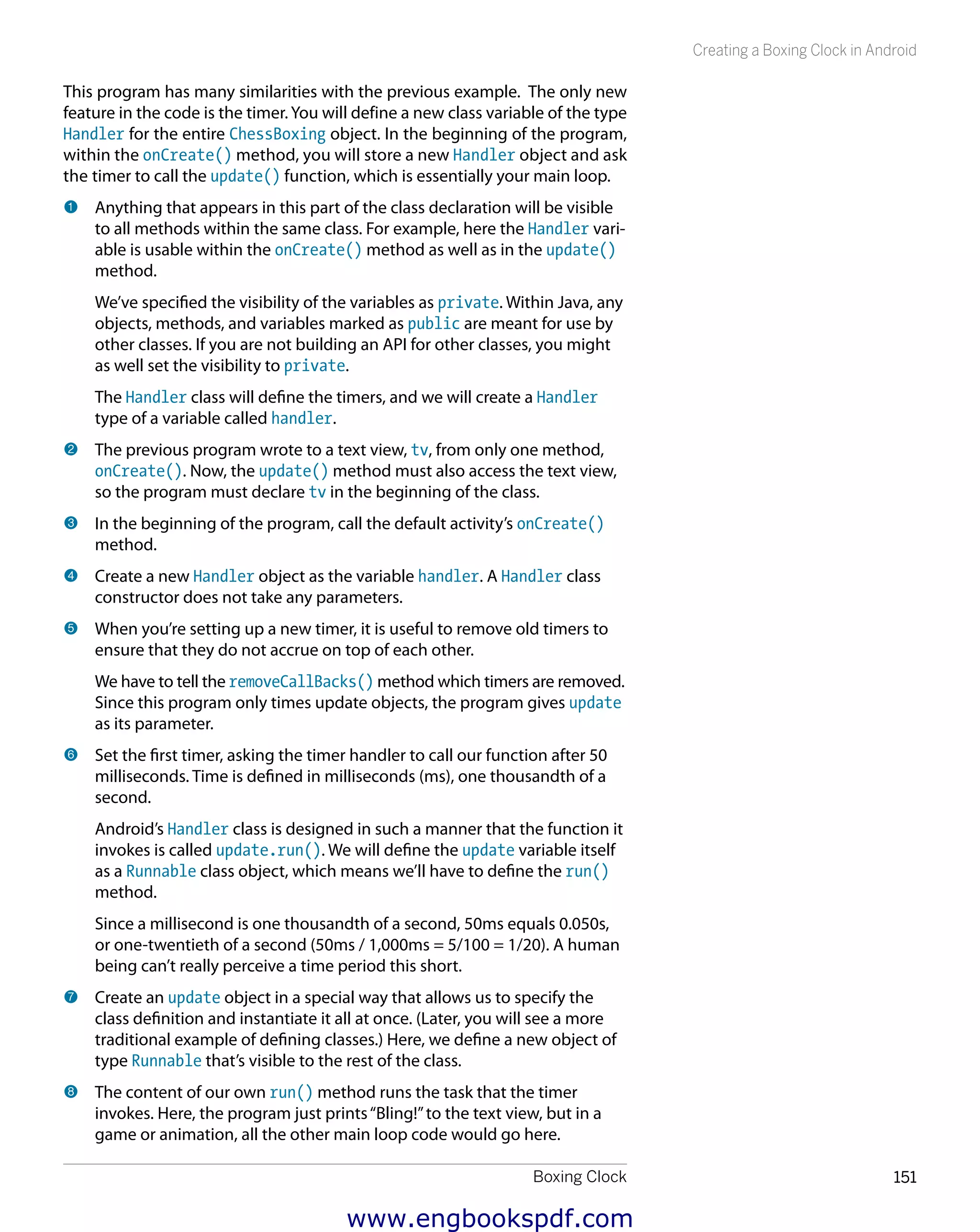
![Creating a Boxing Clock in Android
Chapter 6152
Finally, call the timer again. Just as we did when creating the first timer,
remove all existing timers to prevent them from accumulating.
9 Finally, request to call the update.run() again after 10 seconds. Time is
given in milliseconds. To make it easier to read, it is helpful to specify the
time as a multiplication (10 seconds * 1,000 milliseconds).
Now the program will continue forever—or at least, until the phone is
restarted (or unless the program runs unused in the background for a
time and the OS decides to terminate it).
Adding Sound to the Boxing Clock
When you’re boxing, it can be hard to check your cell phone to see if the round
has ended. It’s time to add sounds to the Boxing Clock to make notification
easier.
The first version of the program will simply play back an MP3. Create a new
project just as you did earlier in the chapter (close any open files from other
projects first). From within Eclipse, choose File→New: Project→Android project.
Set the properties shown in Table 6-1 and click Finish.
Table6-1.Project settings for the MP3 playback example
Setting Value
Project name HelloMp3
BuildTarget 2.1
Application name Hello mp3!
Package name fi.sulautetut.android.hellomp3
Create Activity HelloMp3
Min SDKVersion 7
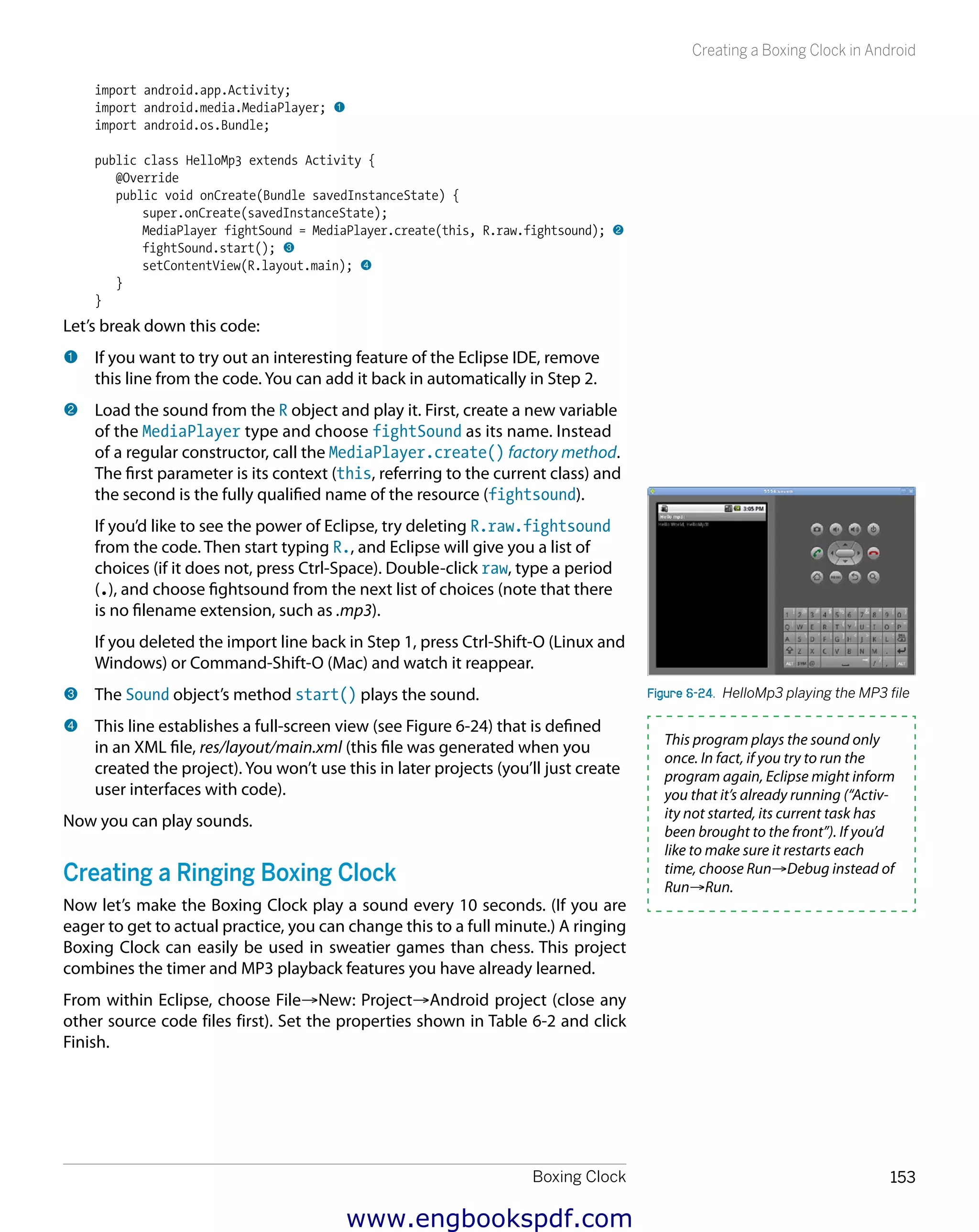
Run the program to make sure it works. When prompted to specify how to run
it, choose Android Application. Now you can customize it to play an MP3.
First, add the fightsound.mp3 MP3 file (download it from http://examples.oreilly
.com/0636920010371) into the project resources. Find the res folder in the
left side of the Eclipse window, create a new folder (right-click on res, choose
New→Folder), and name the new folder raw. Drag fightsound.mp3 into this
folder. When prompted to specify how to copy the file, choose Copy Files.
This MP3 file will not appear on the cell phone’s filesystem. Instead, the Eclipse
project will automatically create and import a class named R that exposes
resources to your code.
Open up the main activity HelloMp3.java (it’s under src/fi.sulautetut.android
.hellomp3). Add the sound handling in the end of its onCreate() method like so:
// bca03helloMp3 - Play a sound
// (c) Kimmo Karvinen & Tero Karvinen http://BotBook.com
package fi.sulautetut.android.hellomp3;
Only lowercase letters, numbers, and
underscores can be used in the file-
names (if you’re familiar with regular
expressions, this class is represented
as [a-z0-9_]).
www.engbookspdf.com](https://image.slidesharecdn.com/makearduinobotsandgadgetslearningbydiscoverybykimmoandterokarvinen-1-201218032819/75/Arduino-Crea-bots-y-gadgets-Arduino-aprendiendo-mediante-el-descubrimiento-de-kimmo-y-tero-karvinen-168-2048.jpg)
![Boxing Clock 161
Creating a Boxing Clock in Android
The fill level is calculated by taking the time elapsed (now-pieStarted)
and dividing it by the time spent for the whole pie (for a round or a
break): pieEnds-pieStarted.
4 Invalidate the view, which causes it to be redrawn (and hence, invokes
the PieView.onDraw() method).
5 The handler timer is responsible for invoking this object’s (named up-
date) run() method. Because you want smooth animations, the wait-
ing period is short. The program uses 50ms (0.050 seconds) here, which
makes the refresh rate (frame rate) 20 frames per second, or 20 hertz
(1/[0.050s] = 20 1/s = 20Hz).
6 A view must be defined as its own class that extends the View class.
In contrast to the static image example shown previously, animations
change between each onDraw() method call. In this case, the drawing is
affected by variable percent, as you’ll see in the onDraw() method.
7 Most drawing commands use Paint class colors, which you can create
immediately with names (Color.GREEN, Color.RED, and so forth) or as
hexadecimal codes (0xff22ffcc). These hexadecimal codes start with
0xff, because the first two digits are reserved for opacity (alpha channel).
8 In Android, the RectF class defines a rectangle. The upper-left-corner
coordinates are 0,0, and use the screen size for the lower-right-corner
coordinates. Because you haven’t set the program to use the full screen,
the beams above push part of the pie beyond the bottom of the picture.
You’ll have a chance to fix this in a later example.
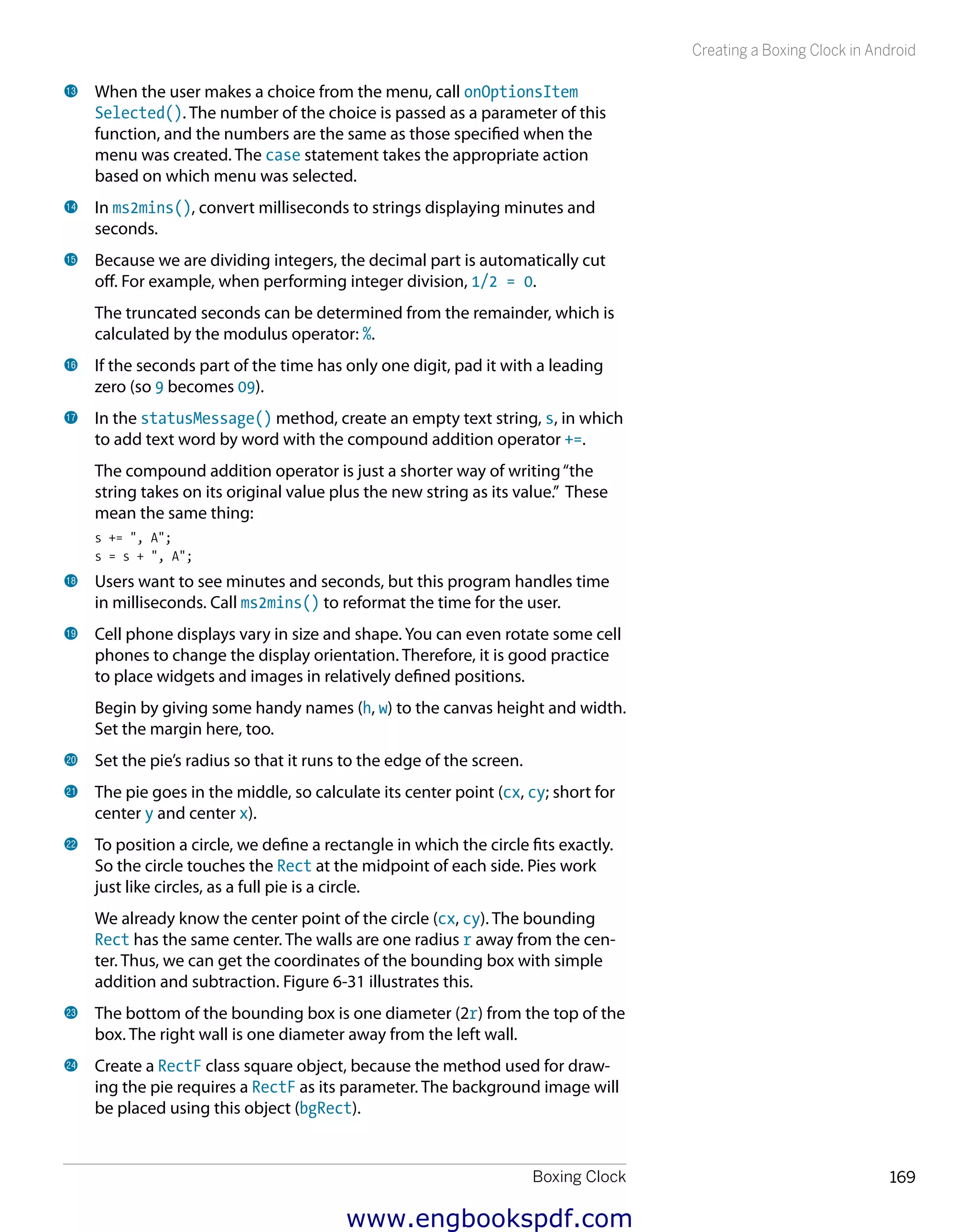
9 The drawArc() method draws the pie (technically, a filled circular sector
bounded by the specified arc) and takes several parameters:
—— The size is specified with a rectangle (Rect) named oval. A fully filled
pie would be the largest circle that fits this rectangle (i.e., the circle
would touch all sides of the rectangle and would have exactly the
same height and width as the rectangle).
—— The fill level is specified by a beginning and end angle in degrees
(360*percent). The degree of the angle of the pie’s ending point
changes continuously. A full circle is 360 degrees.
—— The drawArc() method could also be used for drawing segments,
in which case the second-to-last parameter (known as useCenter)
would be false instead of true as shown here.
—— The color is specified by the configuration of the Paint object named
paint.
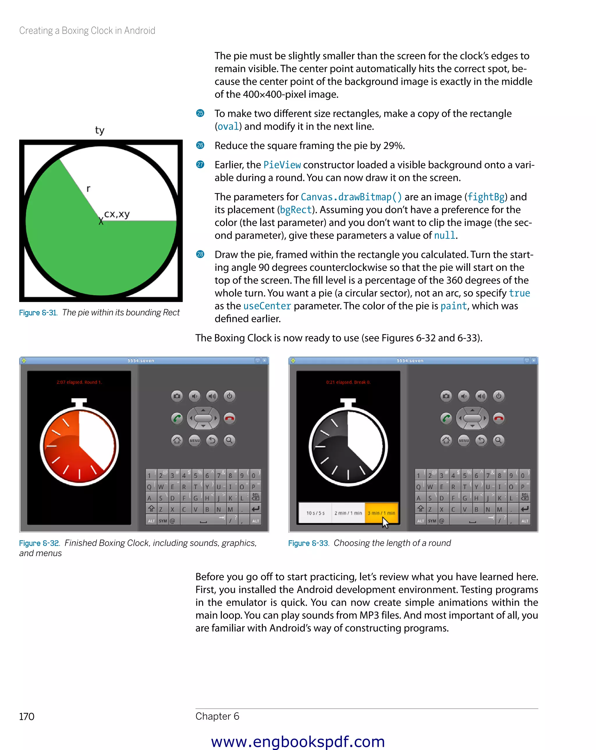
Figure 6-28 shows the result of running the program. Now you understand
how to draw simple animations with Android. Figure 6-28. Animated pie
www.engbookspdf.com](https://image.slidesharecdn.com/makearduinobotsandgadgetslearningbydiscoverybykimmoandterokarvinen-1-201218032819/75/Arduino-Crea-bots-y-gadgets-Arduino-aprendiendo-mediante-el-descubrimiento-de-kimmo-y-tero-karvinen-177-2048.jpg)
![Creating a Boxing Clock in Android
Chapter 6172
Figure 6-35. DDMS perspective showing an unconfigured device
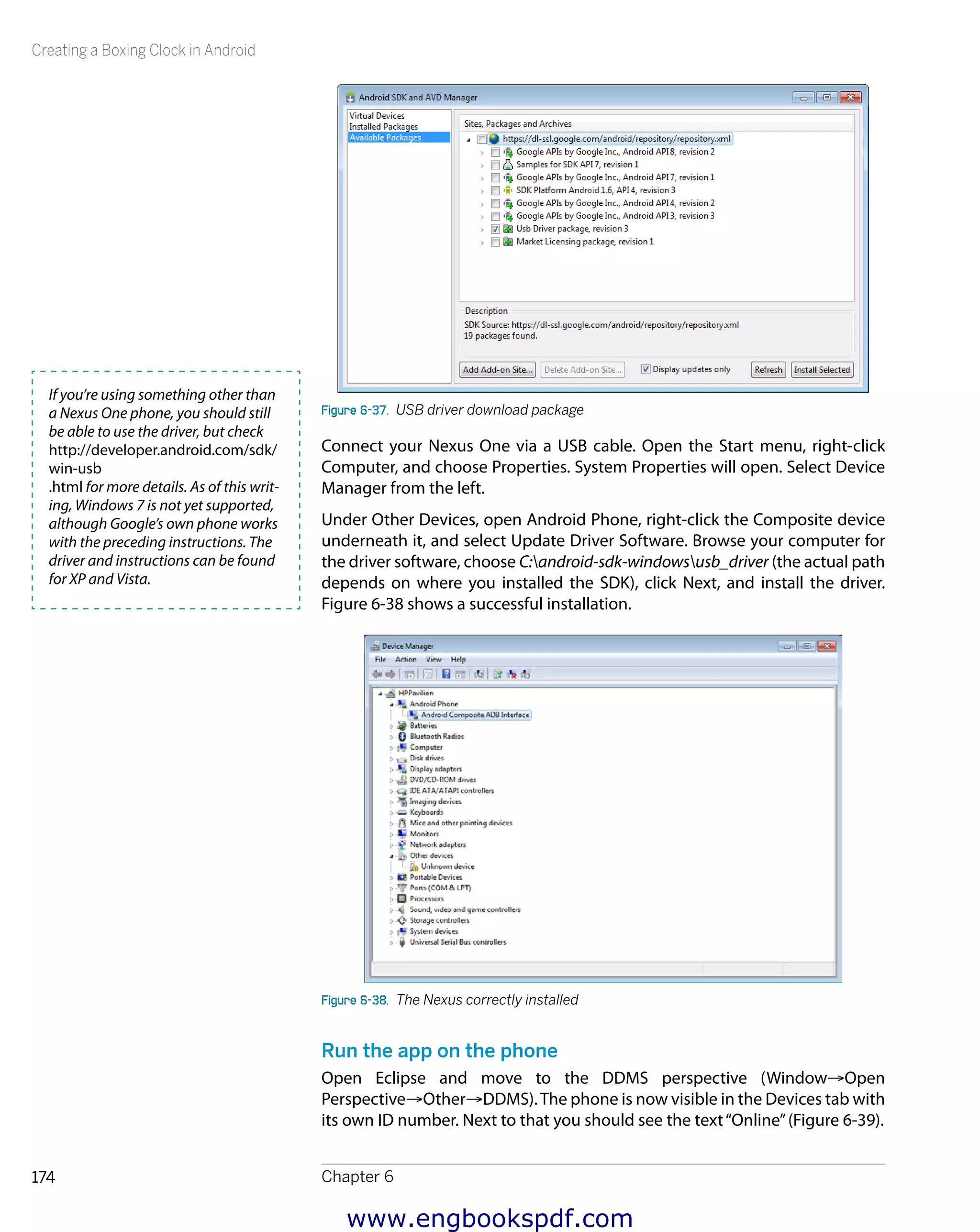
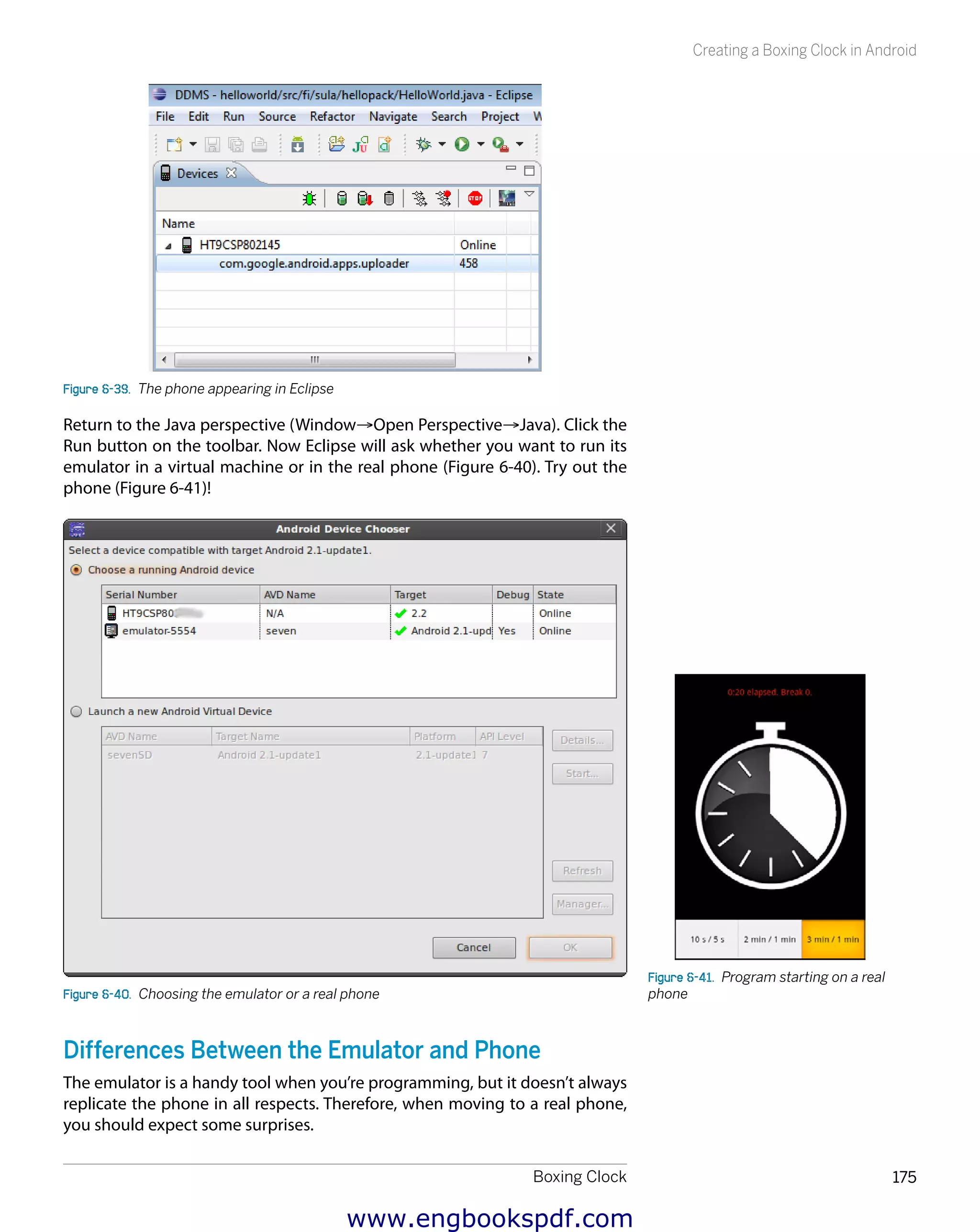
Where is the phone, then? If things worked out, you’ll see an entry for your
phone at the upper left of the screen. On Linux or Windows, you might need
to perform some additional configuration, as described next.
Configure Linux for DDMS
If you see question marks (??????????) and “unknown” devices on the upper-
left side of the Devices tab next to a phone icon, you’ll need to make some
changes.
Close Eclipse. Open a Terminal window, change directory to your home direc-
tory (or wherever the Android SDK was installed), and list the devices known
by Android:
$ cd
$ ./android-sdk-linux_*/platform-tools/adb devices
List of devices attached
???????????? no permissions
You’ll need to configure Ubuntu to give normal (nonroot) users access to the
device. First, you’ll need to determine the USB vendor ID for your phone.
Issue the lsusb command (you might need to provide your password when
prompted):
$ sudo lsusb
[sudo] password for user: *********
...
Bus 001 Device 003: ID 18d1:4e12 Google Inc. Nexus One Phone (Debug)
This displays a long list of devices, but you can recognize your phone by its
name. The list also shows the VendorID (the first four numbers of the ID).
Here, the VendorID is 18d1. To give all users permissions for this device, you
www.engbookspdf.com](https://image.slidesharecdn.com/makearduinobotsandgadgetslearningbydiscoverybykimmoandterokarvinen-1-201218032819/75/Arduino-Crea-bots-y-gadgets-Arduino-aprendiendo-mediante-el-descubrimiento-de-kimmo-y-tero-karvinen-188-2048.jpg)
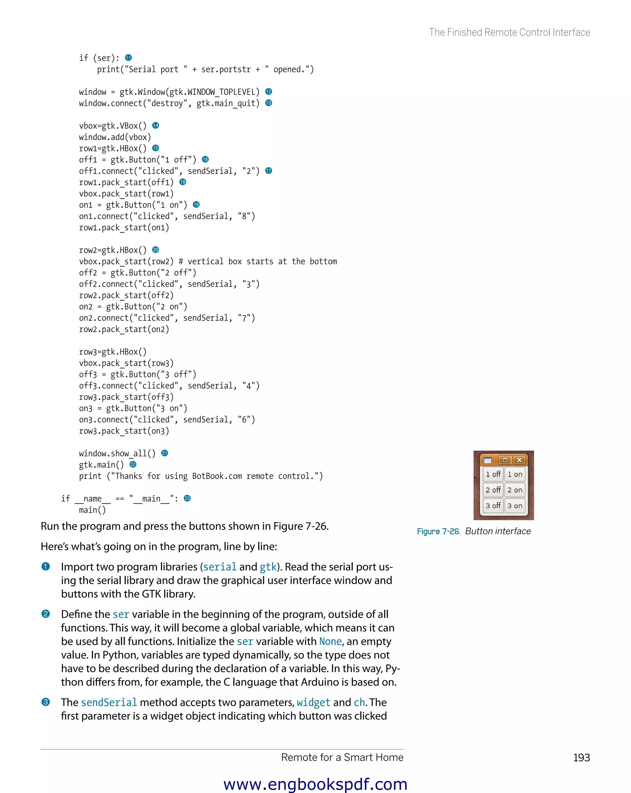
![The Finished Remote Control Interface
Chapter 7194
(e.g., off1, on3, or off2). The other parameter, ch, is the character
to be sent to the Arduino. For example, if the function is invoked as
sendSerial(on1, 8), ch takes on a value of character '8'.
4 Use a global ser variable, visible in all functions. Normally, variables are
visible only in the same block of functions in which they are declared.
Global variables are an exception. Here, the global ser variable is an
object you can use to write to the serial port opened earlier.
5 Display a message to the console to help debug. For example, if you
were sending the character '8', this would display“Sending 8”.
6 Write the ch character, such as '8', to the serial port.
7 This is the main function of the program; the last line of this program will
run main() when the program starts.
8 Use the global ser variable, declared in the beginning of the program.
9 This comment reminds you that you need to change the name of the
serial port (/dev/ttyUSB0) to the name of the serial port Arduino is con-
nected to, such as COM1 on Windows or something like /dev/tty.usbserial
A700dECp on the Mac. In the Arduino IDE, you can confirm which serial
port you are using by clicking Tools→Serial Port. For more information
on Arduino and serial ports, see“Hello World with Arduino”in Chapter 2.
bk Open a connection to the serial port, using 9,600bps as the speed. As the
initial capital letter indicates, serial.Serial is a class. Here, the program
calls the Serial class constructor, which returns a Serial class object
called ser.
bl If the ser object was created successfully, display this text to confirm it.
If the program can’t open the serial port, Python will crash the program
and automatically display an error message before it terminates. The
most common error is trying to open the wrong serial port. Here’s an
example of such an error:
serial.serialutil.SerialException: could not open port /dev/ttyUSB1: [Errno
2] No such file or directory: '/dev/ttyUSB1'
You can correct the error by specifying the correct serial port, as explained
in Step 9.
bm Create a new window object called window. This is the main window of
the program.
bn This gives the user a meaningful way of closing the program, connecting
the window-closing button (usually an X) to the gtk.main_quit() func-
tion. This function ends the main loop. Later on in this function, you’ll see
a call to gtk.main(). After that, the program will display only“Thanks
for using BotBook.com remote control”, so ending the loop will end the
whole program.
bo A window can contain only one widget, such as a button. The interface
needs six buttons, so the program must use boxes (box) to create a
stacked widget box (vbox) to add to the window.
www.engbookspdf.com](https://image.slidesharecdn.com/makearduinobotsandgadgetslearningbydiscoverybykimmoandterokarvinen-1-201218032819/75/Arduino-Crea-bots-y-gadgets-Arduino-aprendiendo-mediante-el-descubrimiento-de-kimmo-y-tero-karvinen-210-2048.jpg)
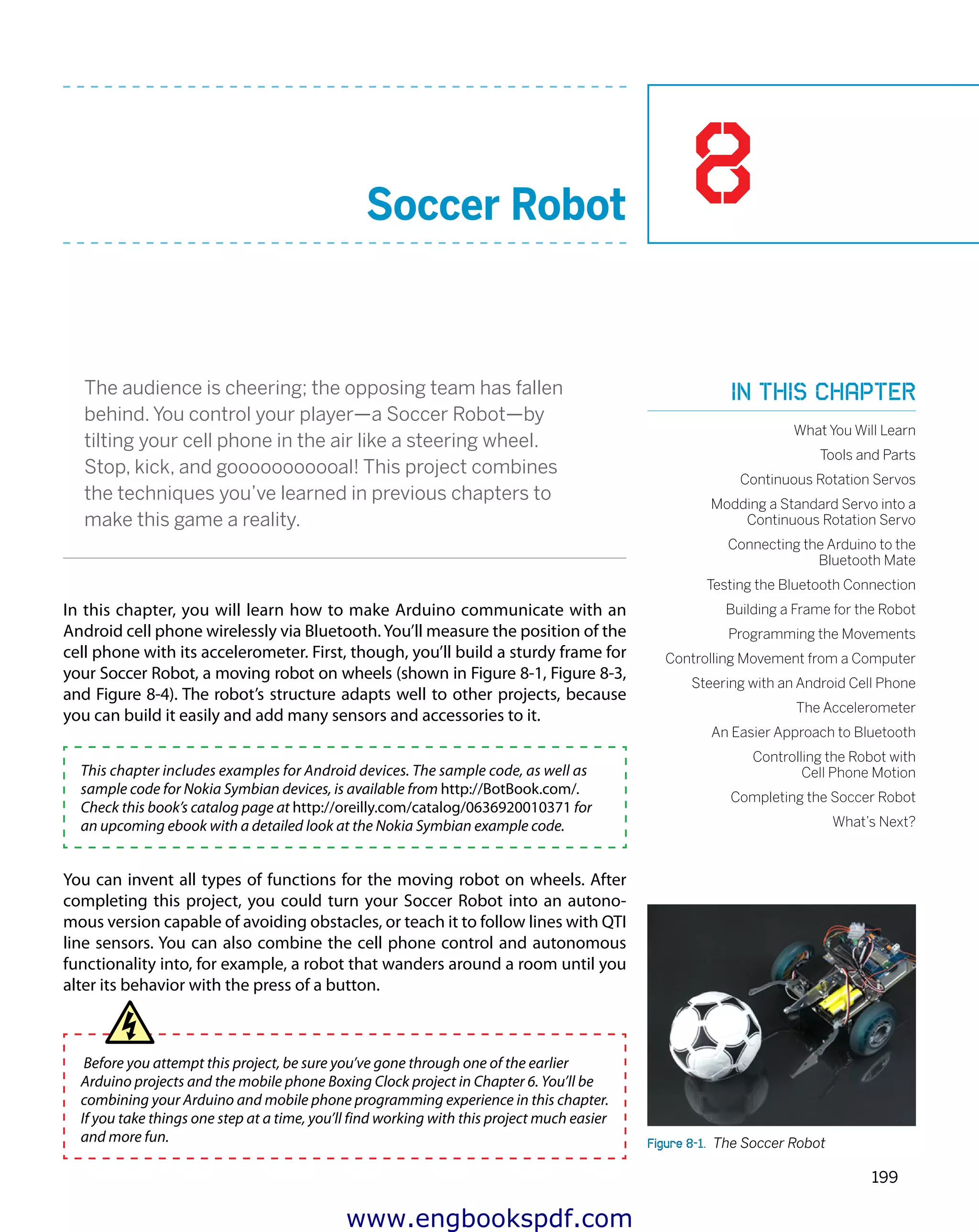
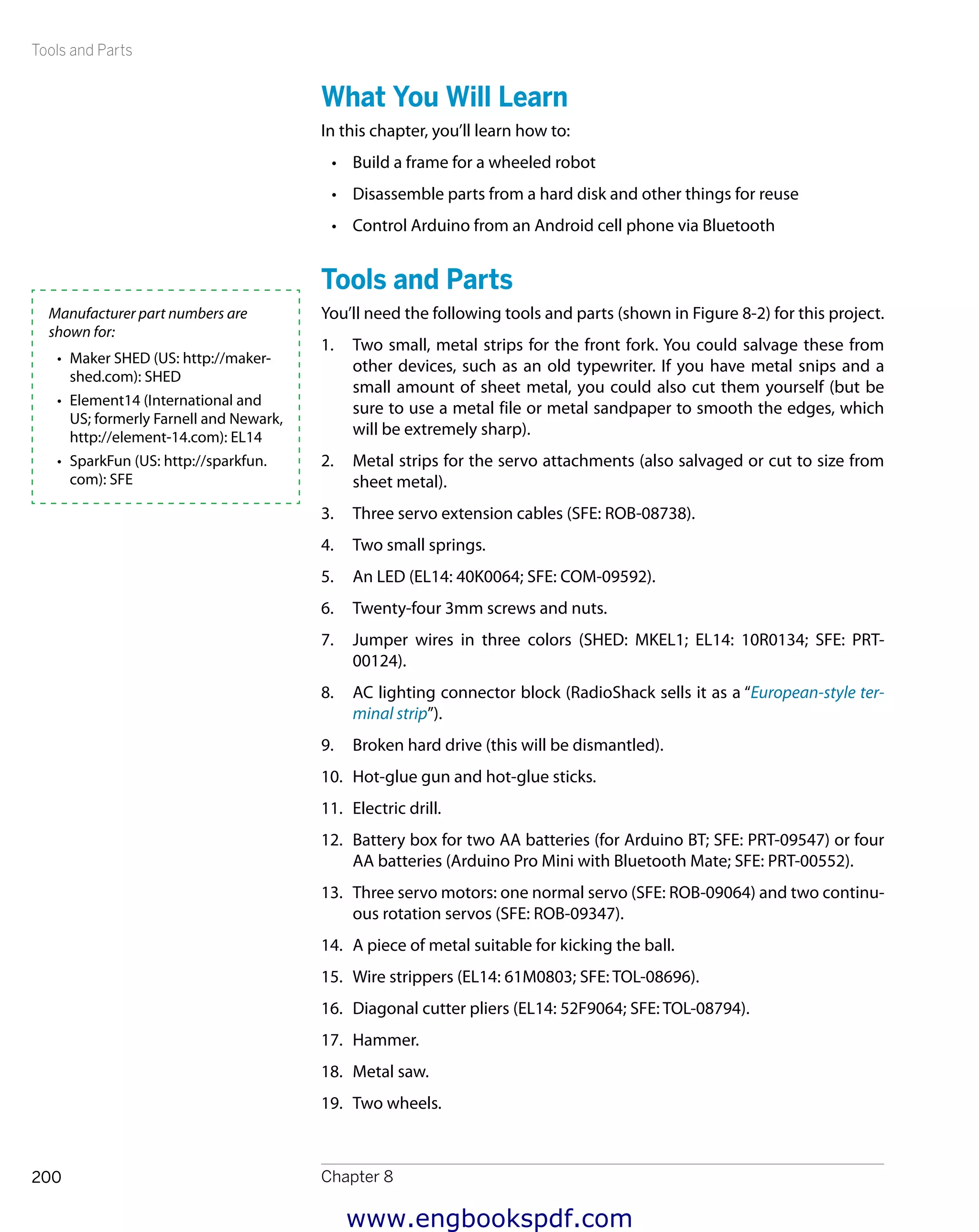


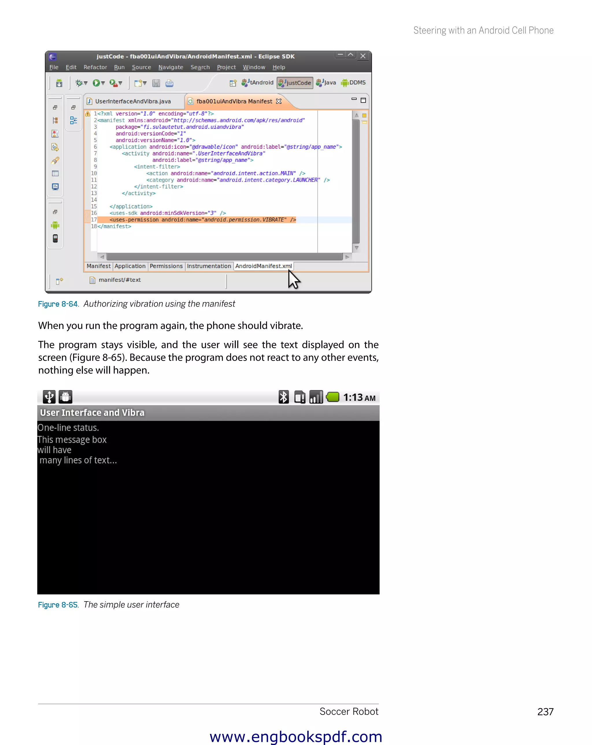

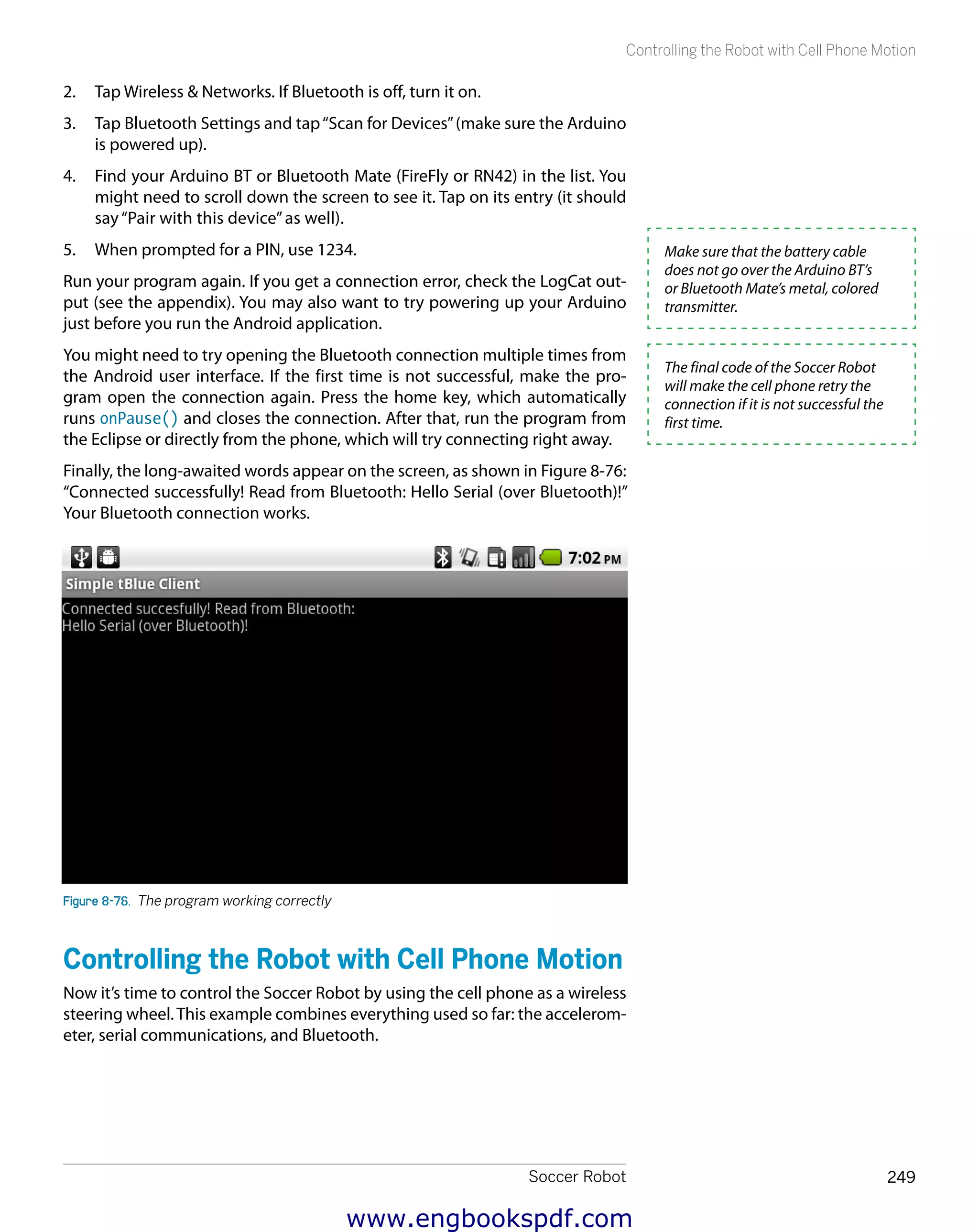
![Soccer Robot 239
The Accelerometer
Replace the contents of Acceleration.java with the following code:
// Acceleration - print accelerometer values
// (c) Tero Karvinen & Kimmo Karvinen http://BotBook.com
package fi.sulautetut.android.acceleration;
import android.app.Activity;
import android.content.pm.ActivityInfo;
import android.hardware.Sensor;
import android.hardware.SensorEvent;
import android.hardware.SensorEventListener;
import android.hardware.SensorManager;
import android.os.Bundle;
import android.view.WindowManager;
import android.widget.LinearLayout;
import android.widget.TextView;
public class Acceleration
extends Activity
implements SensorEventListener 1
{
TextView statusTv; 2
TextView messagesTv;
SensorManager sensorManager;
Sensor sensor;
float g=9.81f; // m/s**2 3
float x, y, z; // gravity along axis, times earth gravity 4
/*** Main - automatically called methods ***/
@Override
public void onCreate(Bundle savedInstanceState) {
super.onCreate(savedInstanceState);
initGUI();
}
@Override
public void onResume()
{
super.onResume();
initAccel(); 5
msg("Running. ");
}
@Override
public void onPause() {
super.onPause();
closeAccel(); 6
msg("Paused. n");
}
@Override
public void onSensorChanged(SensorEvent event) { 7
x=event.values[1]/g; // earth gravity along axis results 1.0
y=event.values[2]/g;
z=event.values[0]/g;
statusTv.setText(String.format( 8
"x: %3.2f y: %3.2f, z: %3.2f",
x, y, z));
www.engbookspdf.com](https://image.slidesharecdn.com/makearduinobotsandgadgetslearningbydiscoverybykimmoandterokarvinen-1-201218032819/75/Arduino-Crea-bots-y-gadgets-Arduino-aprendiendo-mediante-el-descubrimiento-de-kimmo-y-tero-karvinen-255-2048.jpg)


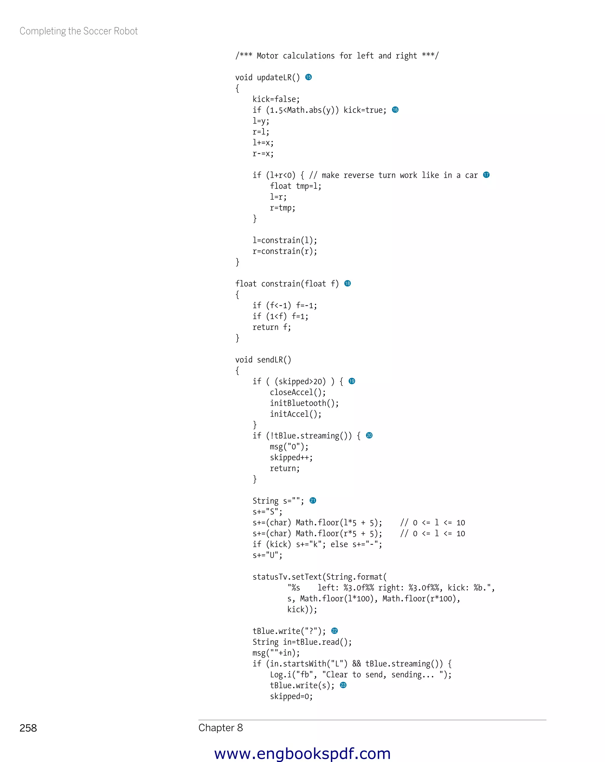
![Completing the Soccer Robot
Chapter 8256
timerHandler.postDelayed(sendToArduino, 1000); 9
skipped=9999; // force Bluetooth reconnection bk
}
@Override
public void onPause() {
super.onPause();
r = 0; bl
l = 0;
sendLR();
closeAccel();
closeBluetooth();
timerHandler.removeCallbacks(sendToArduino); bm
msg("Paused. n");
}
@Override
public void onSensorChanged(SensorEvent event) {
x=event.values[1]/g; // earth gravity along axis results 1.0
y=event.values[2]/g;
z=event.values[0]/g;
updateLR(); bn
}
@Override
public void onAccuracyChanged(Sensor sensor, int accuracy) {
// Must have when Activity implements SensorEventListener.
}
/*** User interface ***/
void initGUI()
{
// Window
setRequestedOrientation(
ActivityInfo.SCREEN_ORIENTATION_LANDSCAPE);
getWindow().setFlags(
WindowManager.LayoutParams.FLAG_KEEP_SCREEN_ON,
WindowManager.LayoutParams.FLAG_KEEP_SCREEN_ON);
// Contents
LinearLayout container=new LinearLayout(this);
container.setOrientation(android.widget.LinearLayout.VERTICAL);
statusTv = new TextView(this);
Log.i("FB", "User interface half way.. ");
container.addView(statusTv);
//msg("statusTv added. ");
messagesTv = new TextView(this);
messagesTv.setText("");
container.addView(messagesTv);
setContentView(container);
}
www.engbookspdf.com](https://image.slidesharecdn.com/makearduinobotsandgadgetslearningbydiscoverybykimmoandterokarvinen-1-201218032819/75/Arduino-Crea-bots-y-gadgets-Arduino-aprendiendo-mediante-el-descubrimiento-de-kimmo-y-tero-karvinen-272-2048.jpg)
![
Appendix A264
{
this.address=address.toUpperCase(); 1
localAdapter = BluetoothAdapter.getDefaultAdapter(); 2
if ((localAdapter!=null) && localAdapter.isEnabled()) {
Log.i(TAG, "Bluetooth adapter found and enabled on phone. ");
} else {
Log.e(TAG, "Bluetooth adapter NOT FOUND or NOT ENABLED!");
return;
}
connect(); 3
}
public void connect()
{
Log.i(TAG, "Bluetooth connecting to "+address+"...");
try {
remoteDevice = localAdapter.getRemoteDevice(address); 4
} catch (IllegalArgumentException e) {
Log.e(TAG, "Failed to get remote device with MAC address."
+"Wrong format? MAC address must be upper case. ",
e);
return;
}
Log.i(TAG, "Creating RFCOMM socket...");
try {
Method m = remoteDevice.getClass().getMethod
("createRfcommSocket", new Class[] { int.class });
socket = (BluetoothSocket) m.invoke(remoteDevice, 1); 5
Log.i(TAG, "RFCOMM socket created.");
} catch (NoSuchMethodException e) {
Log.i(TAG, "Could not invoke createRfcommSocket.");
e.printStackTrace();
} catch (IllegalArgumentException e) {
Log.i(TAG, "Bad argument with createRfcommSocket.");
e.printStackTrace();
} catch (IllegalAccessException e) {
Log.i(TAG, "Illegal access with createRfcommSocket.");
e.printStackTrace();
} catch (InvocationTargetException e) {
Log.i(TAG, "Invocation target exception: createRfcommSocket.");
e.printStackTrace();
}
Log.i(TAG, "Got socket for device "+socket.getRemoteDevice());
localAdapter.cancelDiscovery(); 6
Log.i(TAG, "Connecting socket...");
try {
socket.connect(); 7
Log.i(TAG, "Socket connected.");
} catch (IOException e) {
try {
Log.e(TAG, "Failed to connect socket. ", e);
socket.close();
Log.e(TAG, "Socket closed because of an error. ", e);
} catch (IOException eb) {
Log.e(TAG, "Also failed to close socket. ", eb);
}
return;
}
www.engbookspdf.com](https://image.slidesharecdn.com/makearduinobotsandgadgetslearningbydiscoverybykimmoandterokarvinen-1-201218032819/75/Arduino-Crea-bots-y-gadgets-Arduino-aprendiendo-mediante-el-descubrimiento-de-kimmo-y-tero-karvinen-280-2048.jpg)
![tBlue Library for Android 265
try {
outStream = socket.getOutputStream(); 8
Log.i(TAG, "Output stream open.");
inStream = socket.getInputStream();
Log.i(TAG, "Input stream open.");
} catch (IOException e) {
Log.e(TAG, "Failed to create output stream.", e);
}
return;
}
public void write(String s) 9
{
Log.i(TAG, "Sending ""+s+""... ");
byte[] outBuffer= s.getBytes(); bk
try {
outStream.write(outBuffer);
} catch (IOException e) {
Log.e(TAG, "Write failed.", e);
}
}
public boolean streaming() bl
{
return ( (inStream!=null) && (outStream!=null) );
}
public String read() bm
{
if (!streaming()) return ""; bn
String inStr="";
try {
if (0<inStream.available()) {
byte[] inBuffer = new byte[1024];
int bytesRead = inStream.read(inBuffer);
inStr = new String(inBuffer, "ASCII");
inStr=inStr.substring(0, bytesRead); bo
Log.i(TAG, "byteCount: "+bytesRead+ ", inStr: "+inStr);
}
} catch (IOException e) {
Log.e(TAG, "Read failed", e);
}
return inStr;
}
public void close()
{
Log.i(TAG, "Bluetooth closing... ");
try {
socket.close(); bp
Log.i(TAG, "BT closed");
} catch (IOException e2) {
Log.e(TAG, "Failed to close socket. ", e2);
}
}
}
www.engbookspdf.com](https://image.slidesharecdn.com/makearduinobotsandgadgetslearningbydiscoverybykimmoandterokarvinen-1-201218032819/75/Arduino-Crea-bots-y-gadgets-Arduino-aprendiendo-mediante-el-descubrimiento-de-kimmo-y-tero-karvinen-281-2048.jpg)


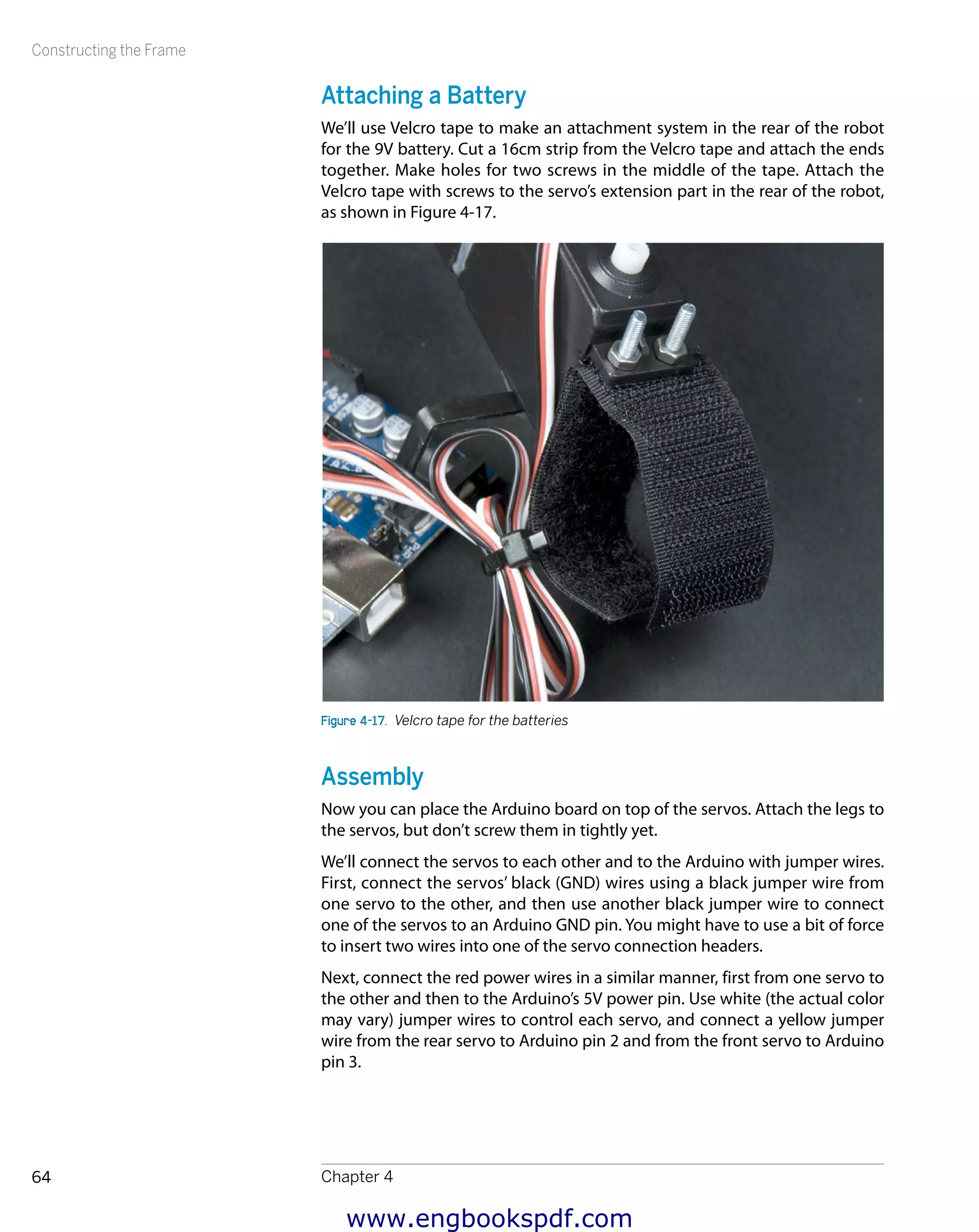
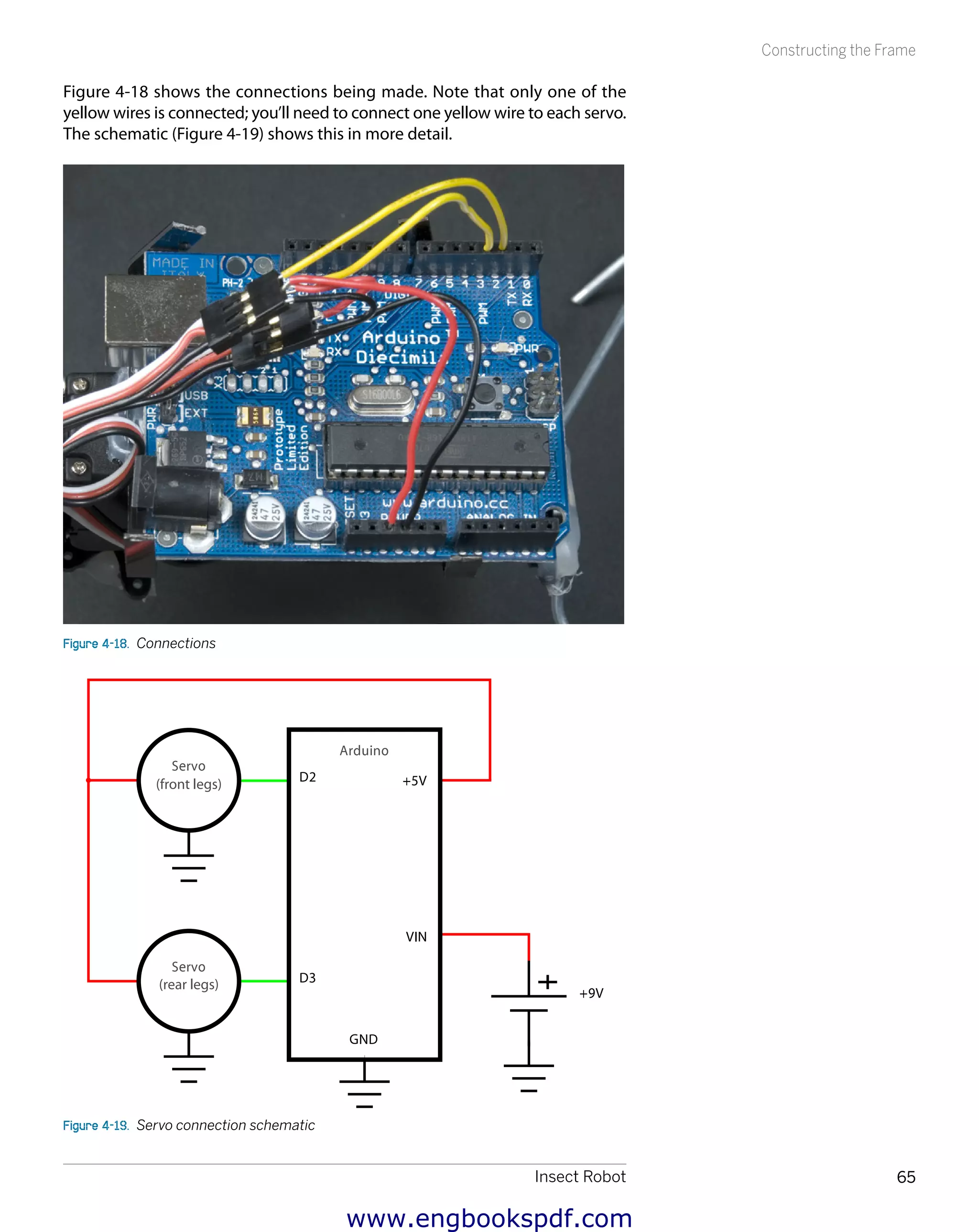
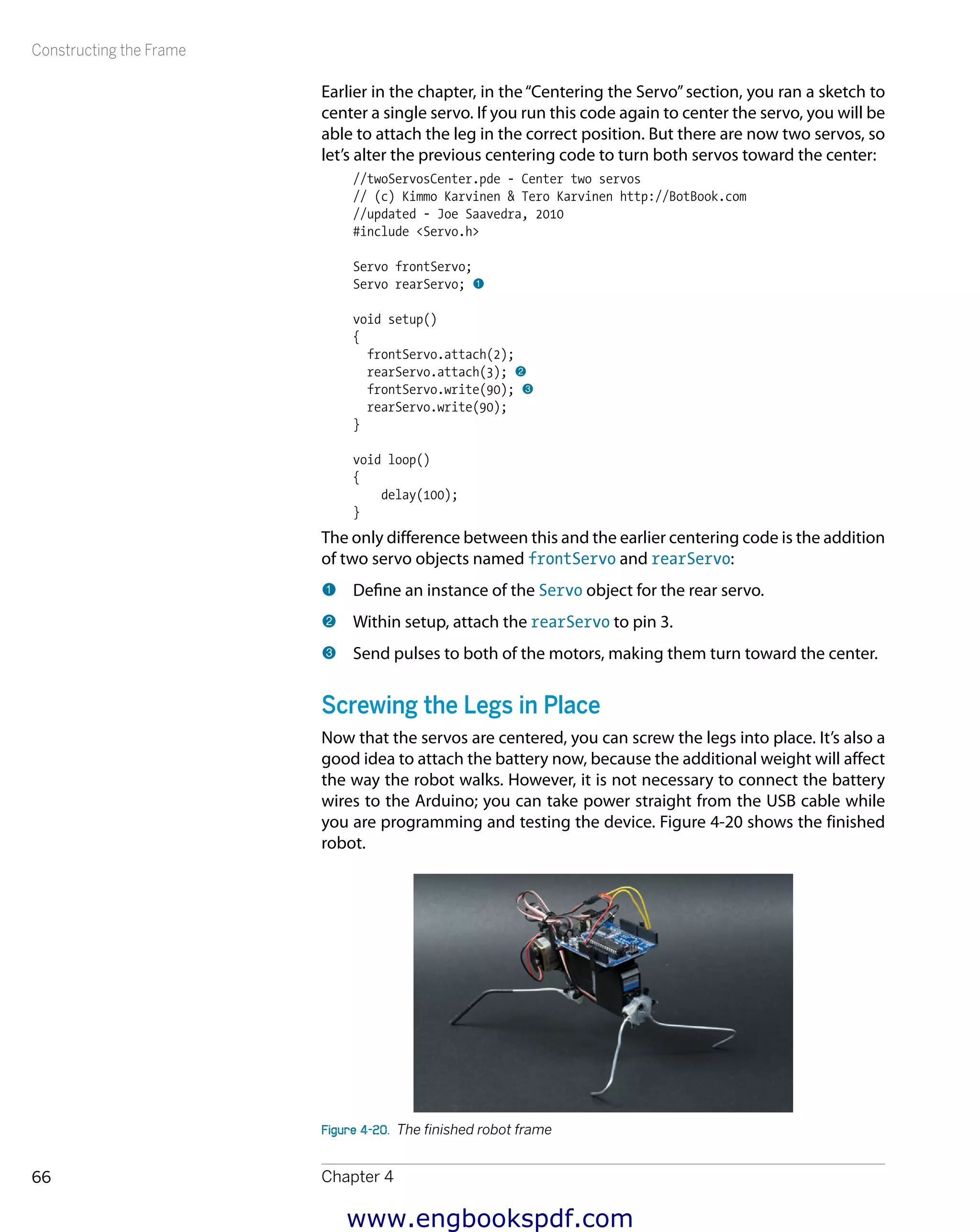
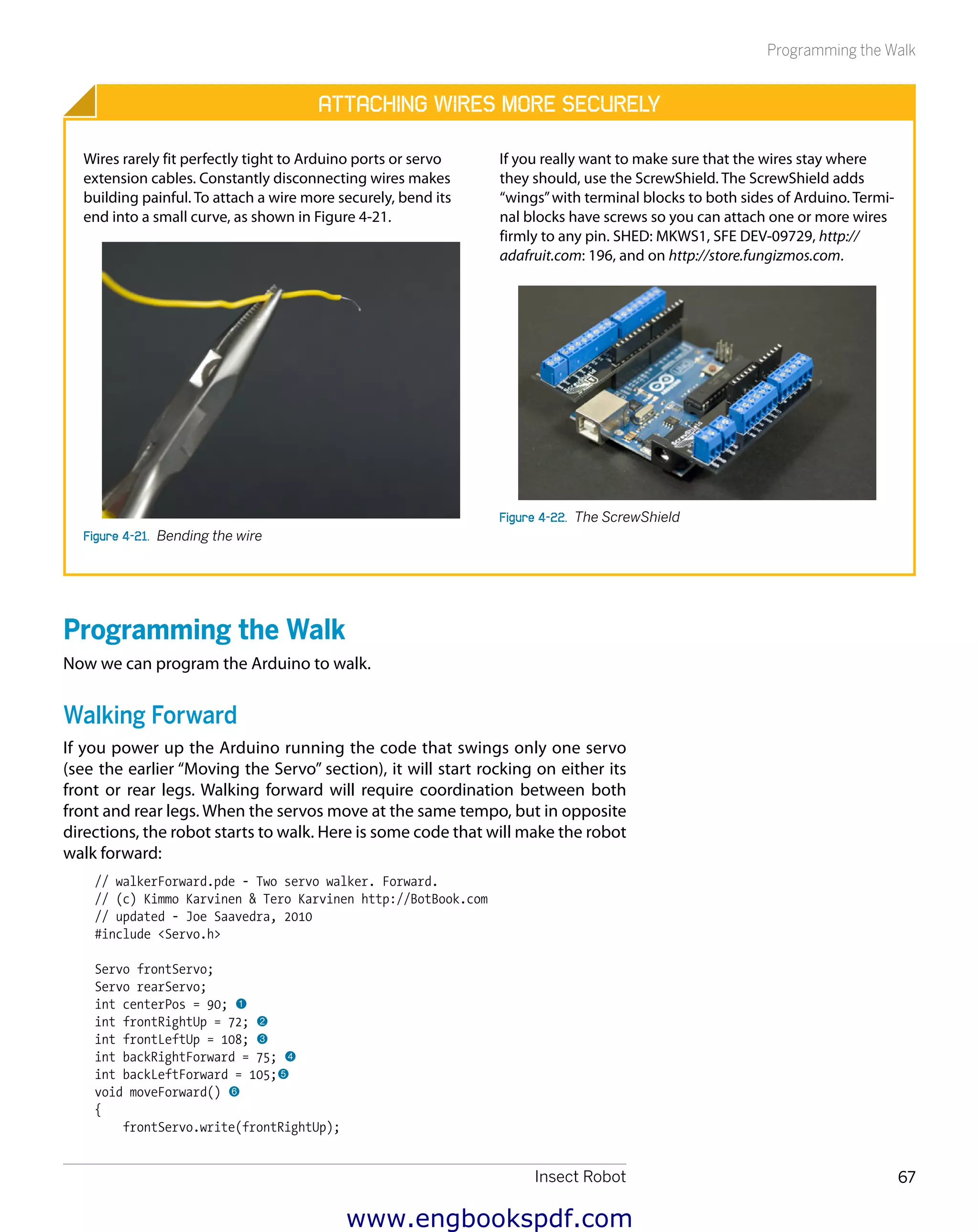
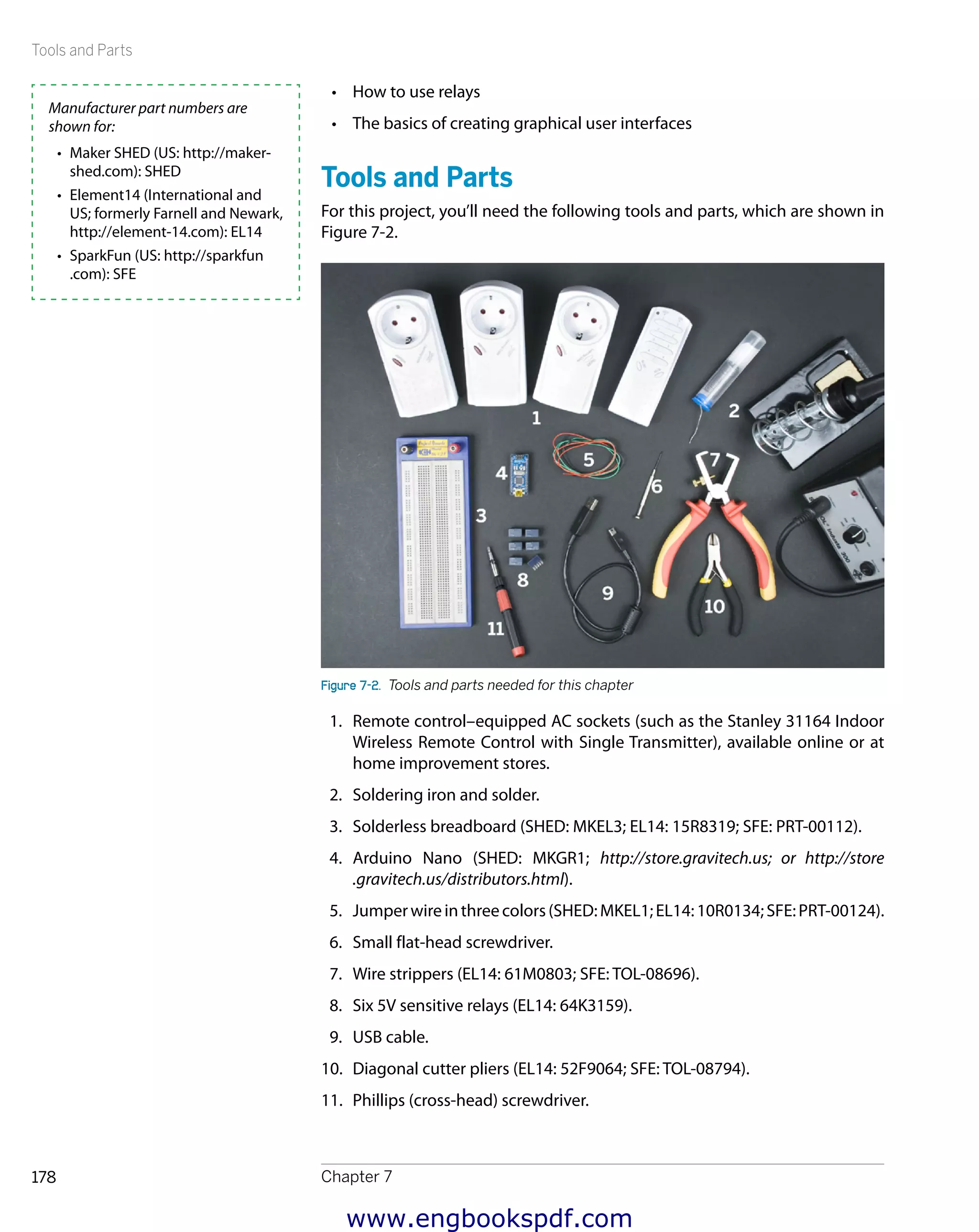
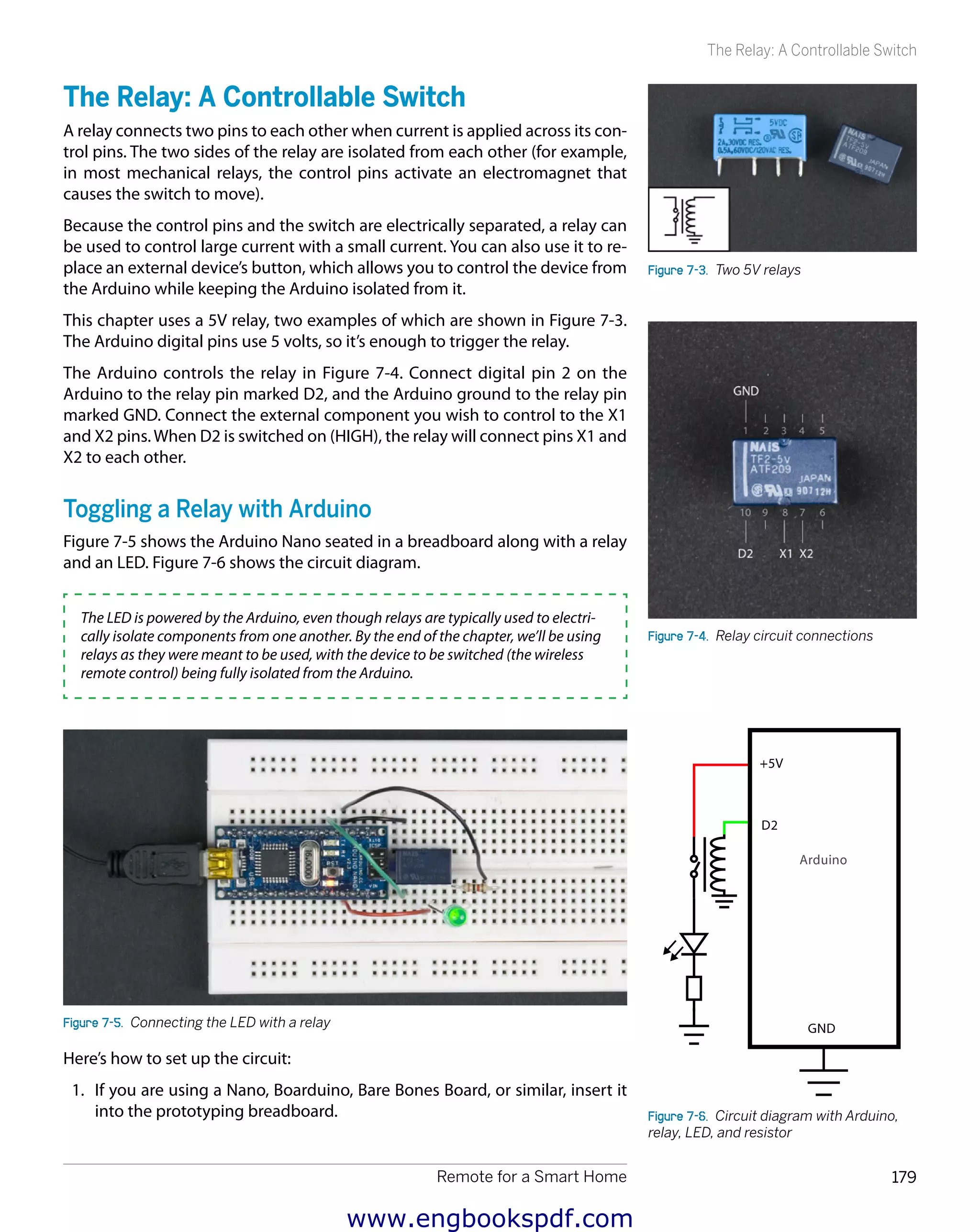
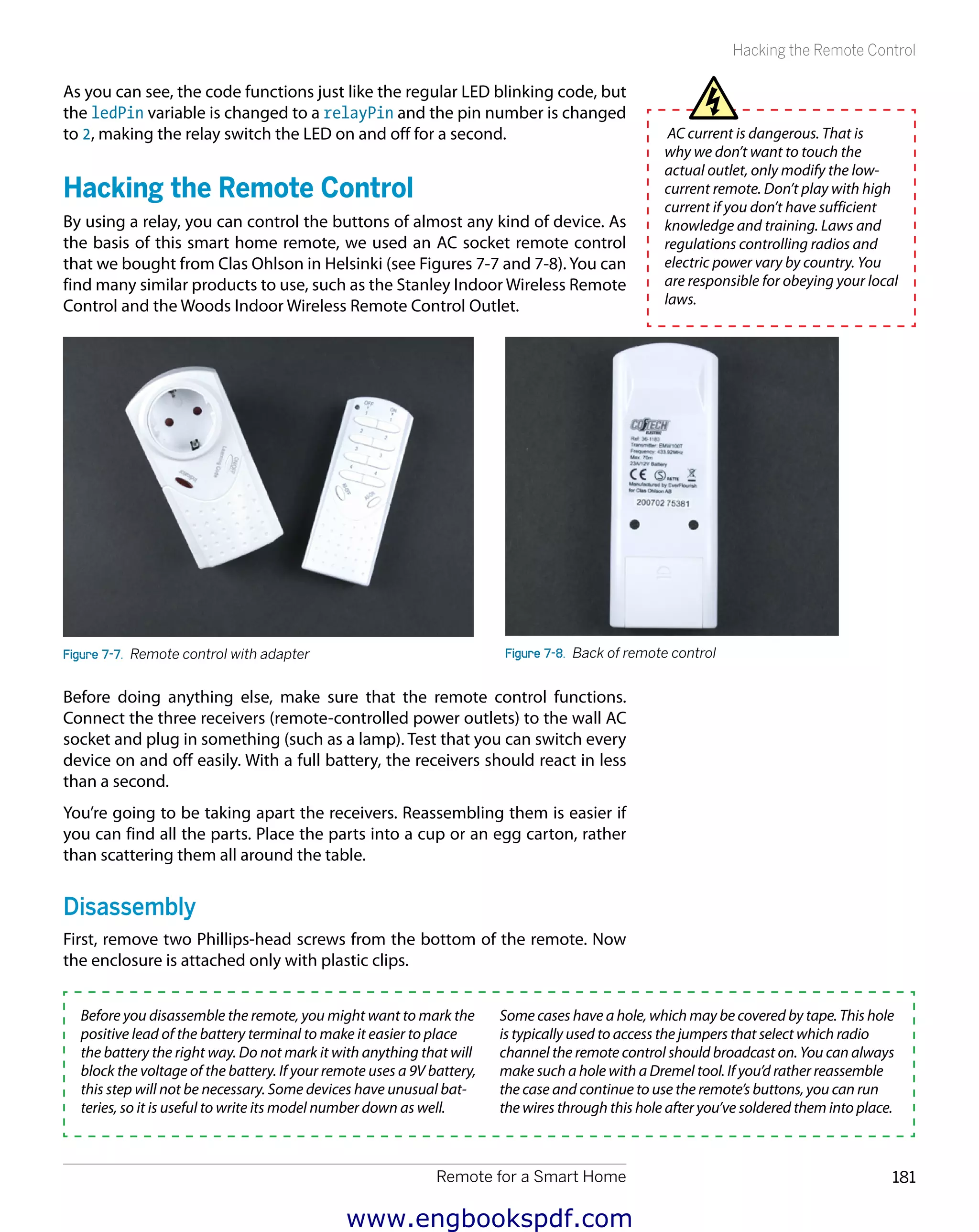
This document is a preface and table of contents for the book "Make: Arduino Bots and Gadgets" by Kimmo and Tero Karvinen. The preface discusses safety considerations for projects in the book. The table of contents provides an overview of the 5 chapters in the book, which cover building basic bots and gadgets using Arduino, including a stalker guard that detects movement using ultrasonic sensors, an insect robot that walks and avoids obstacles, and an interactive painting project that detects hand gestures to control images displayed on a screen.