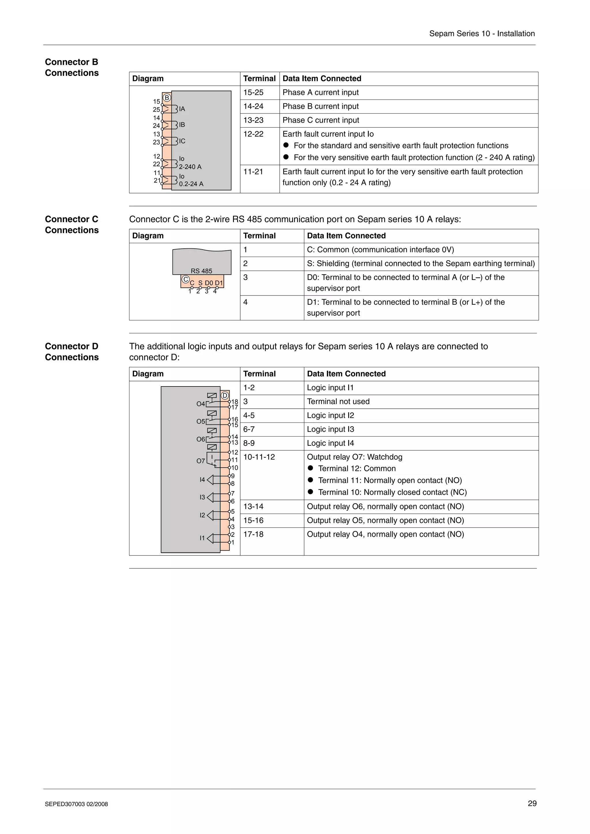
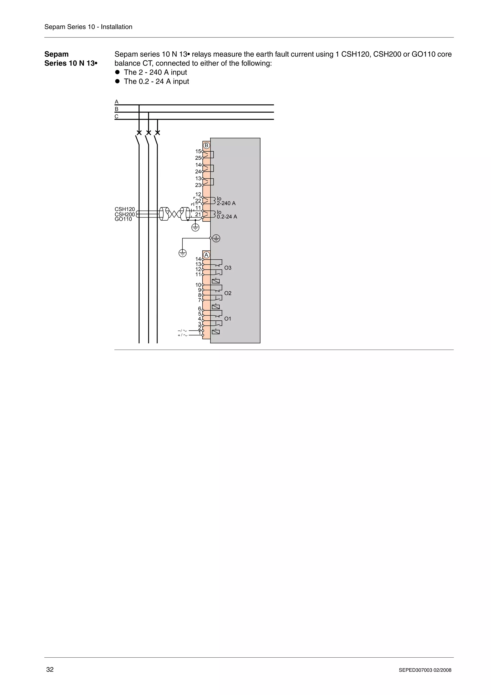
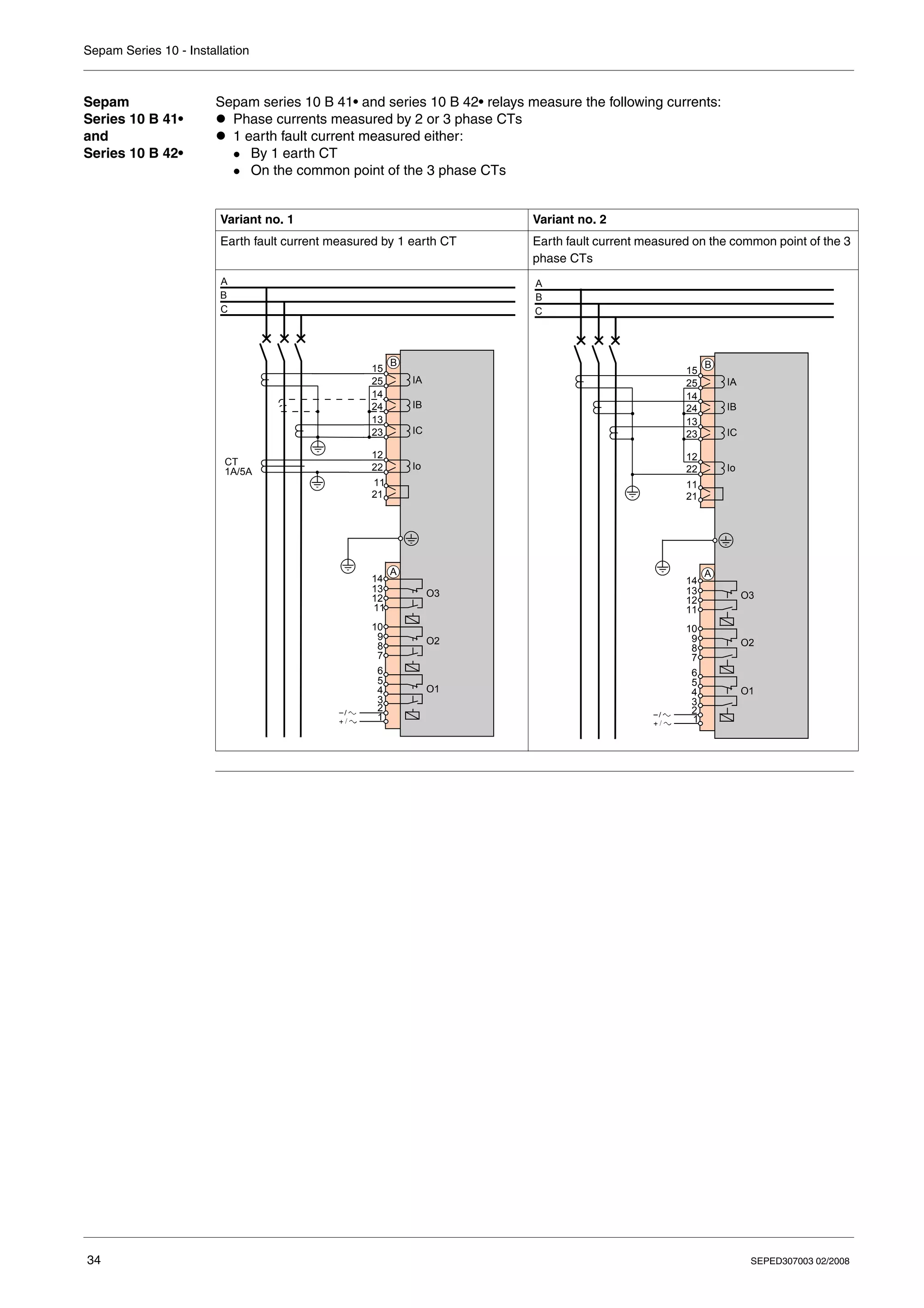
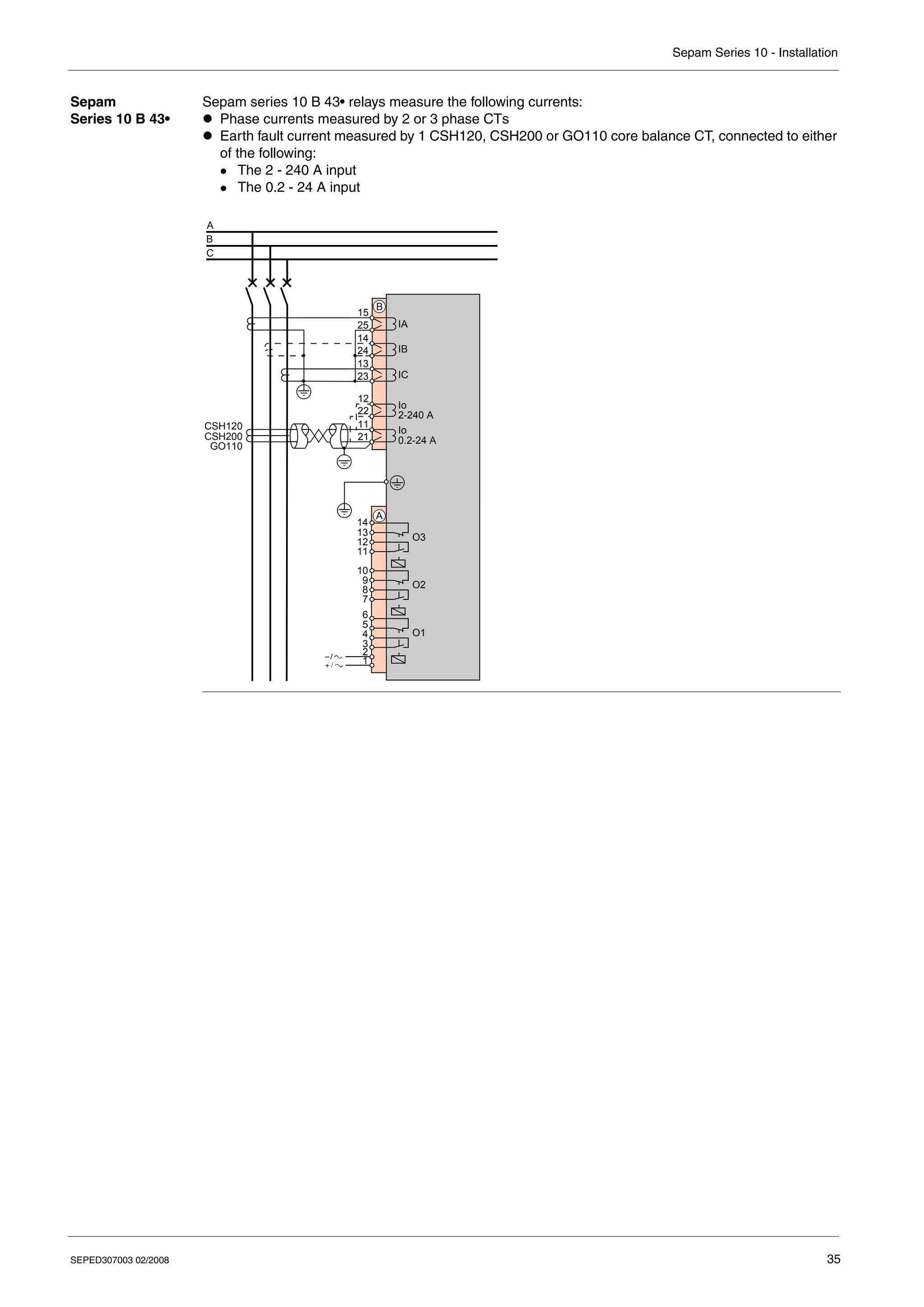
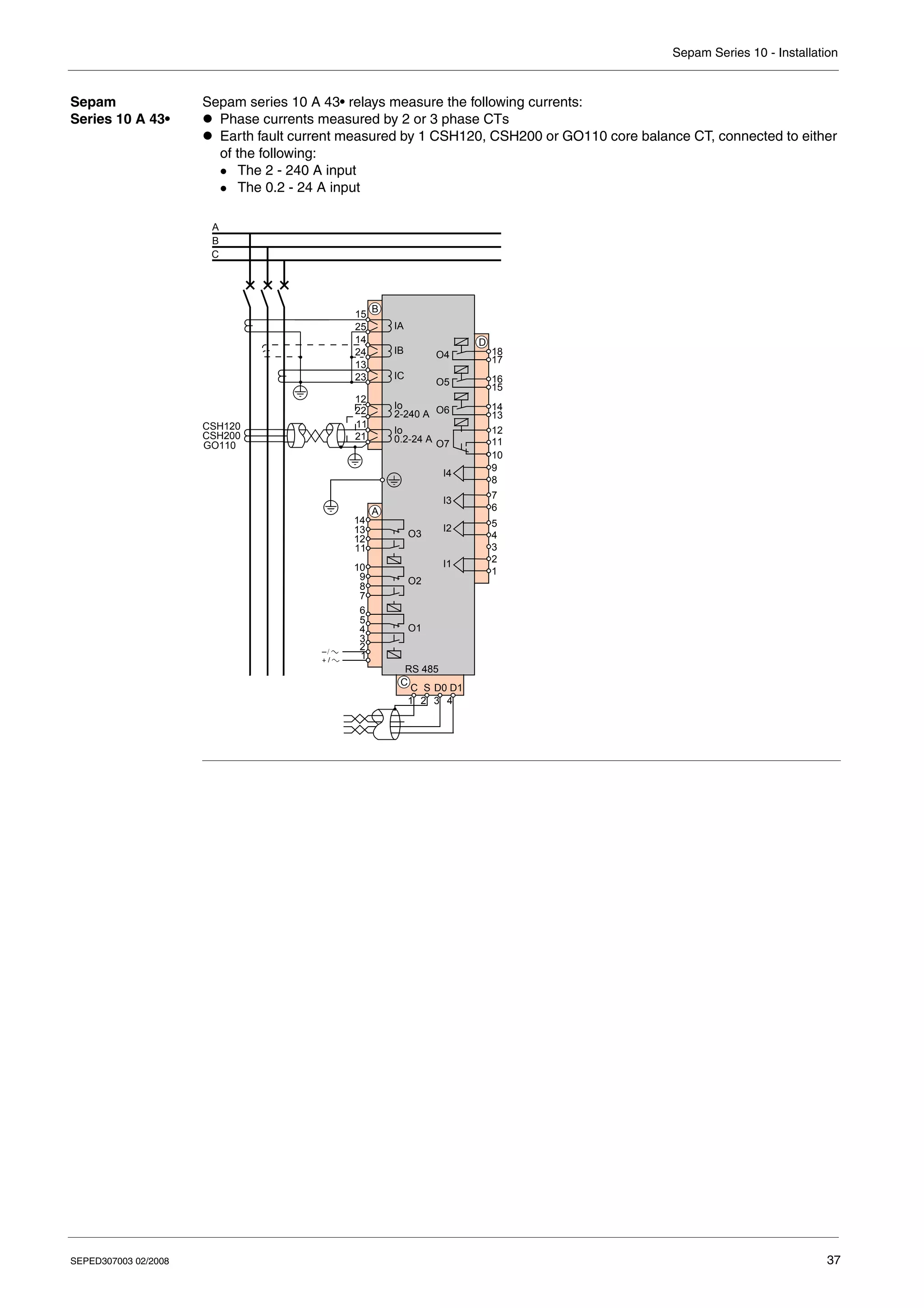
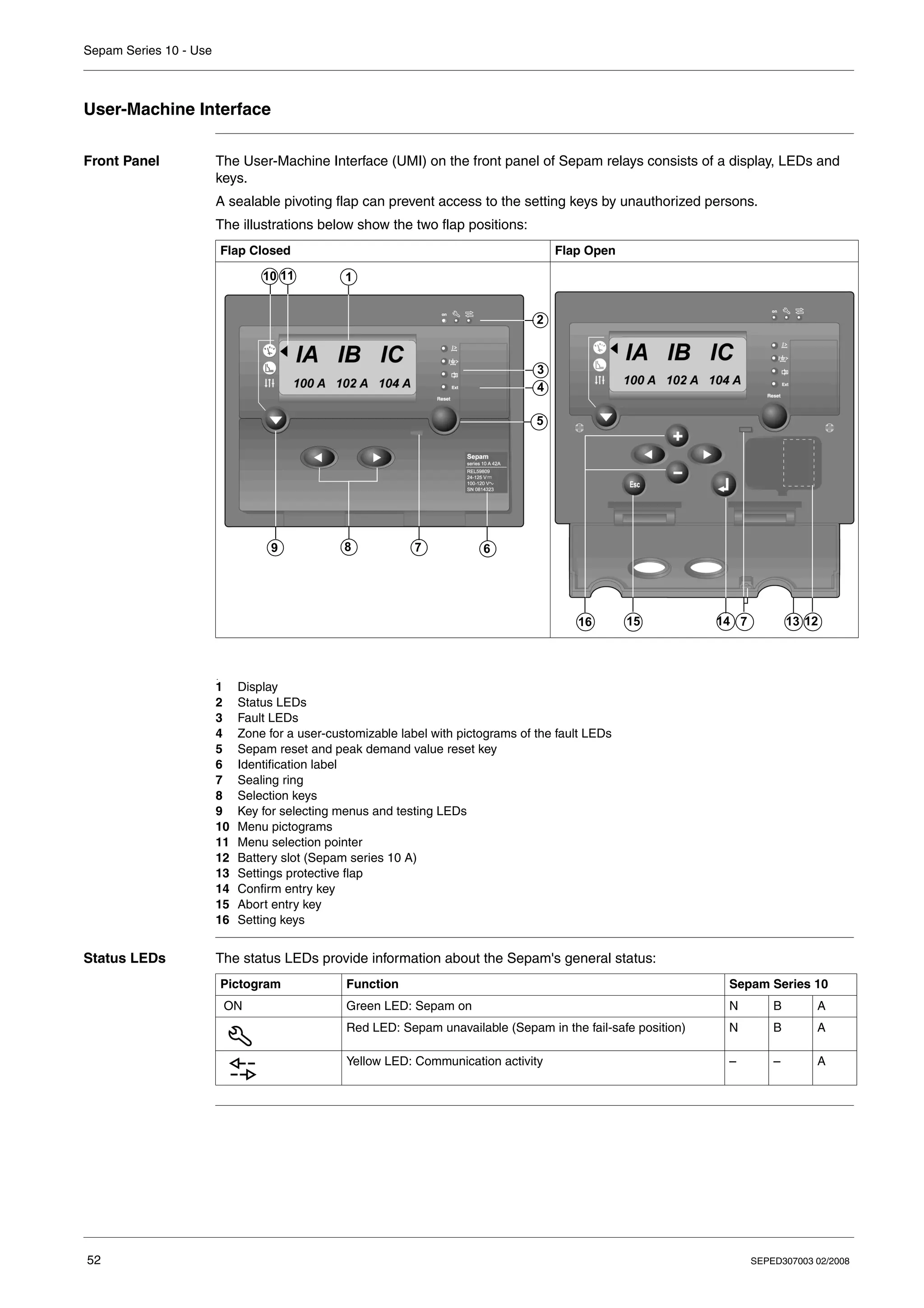
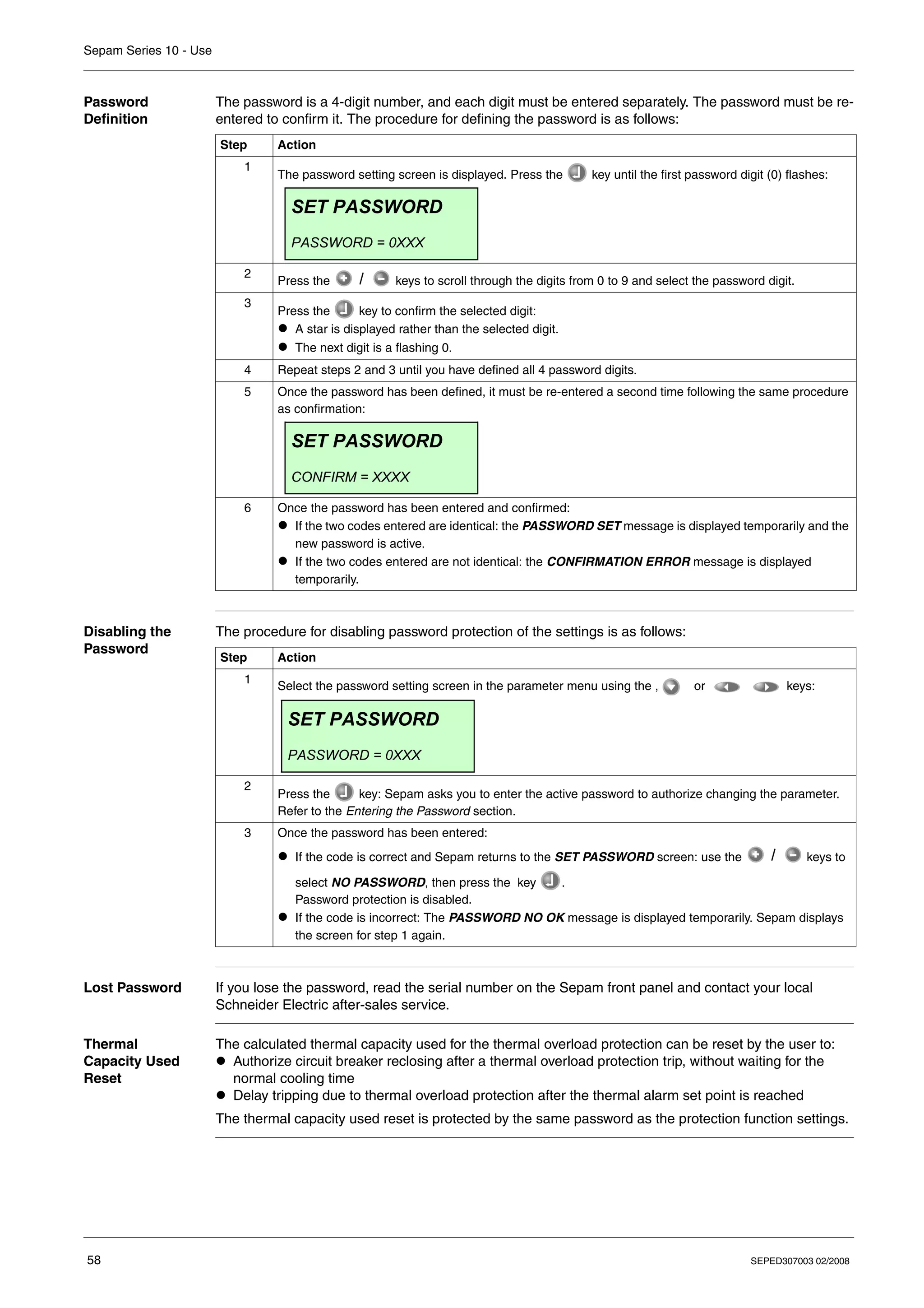
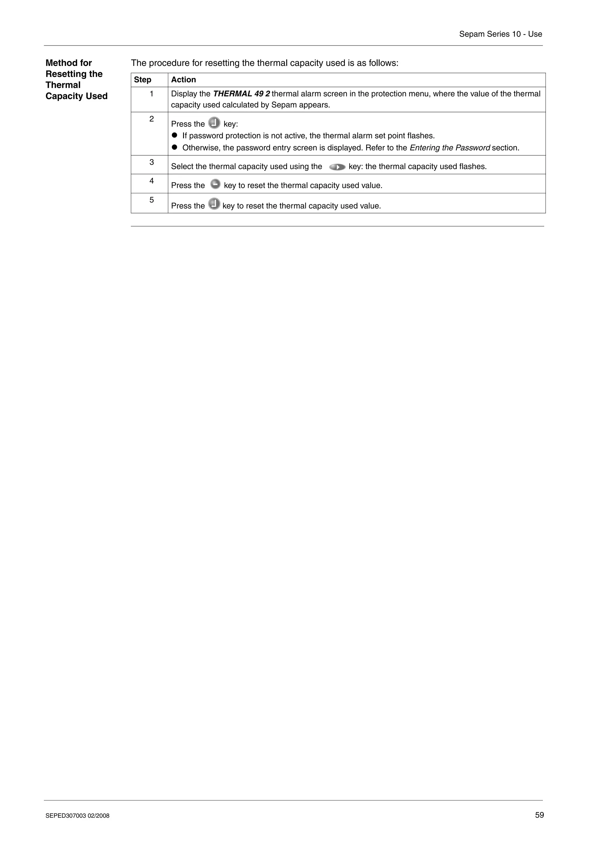
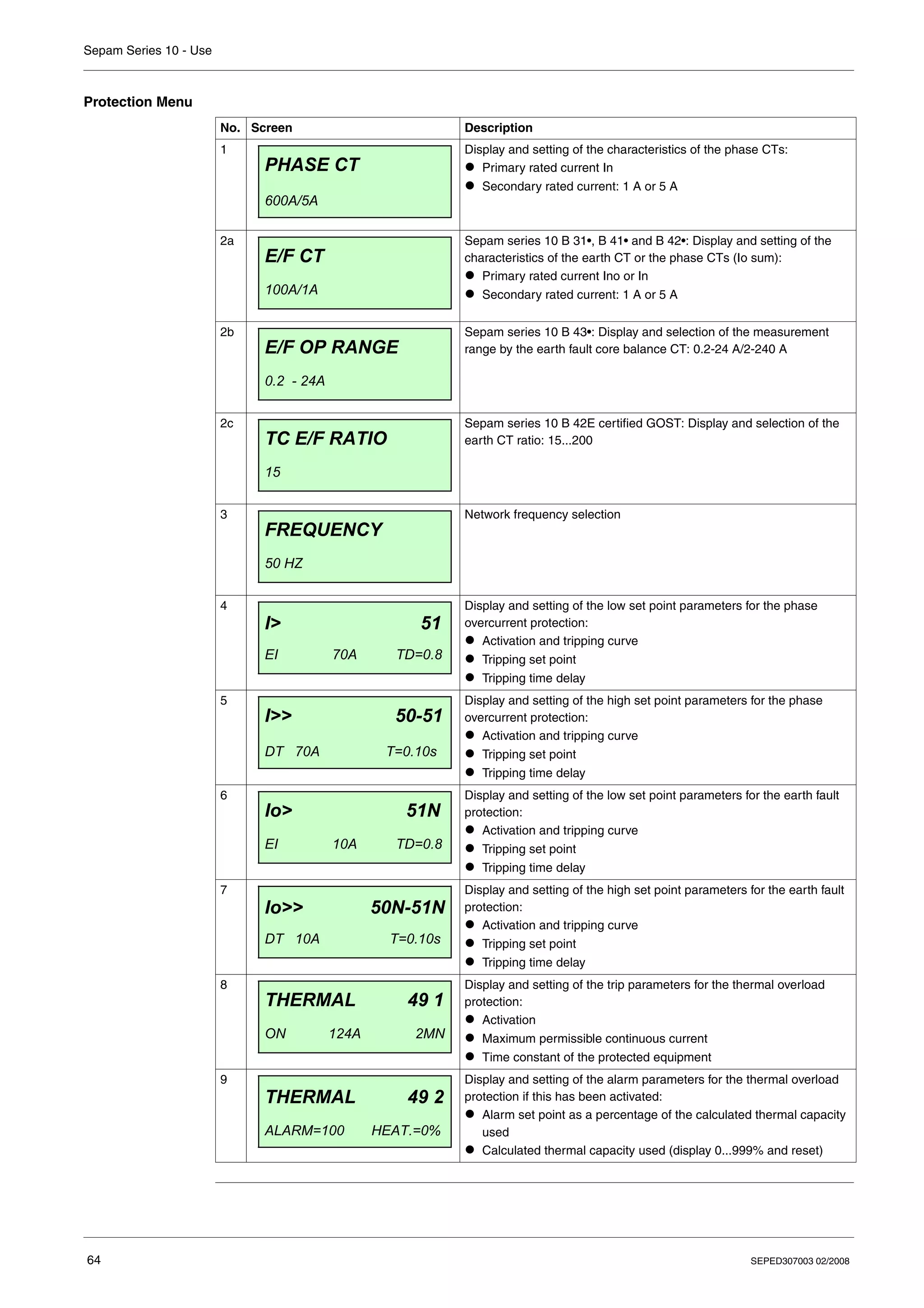
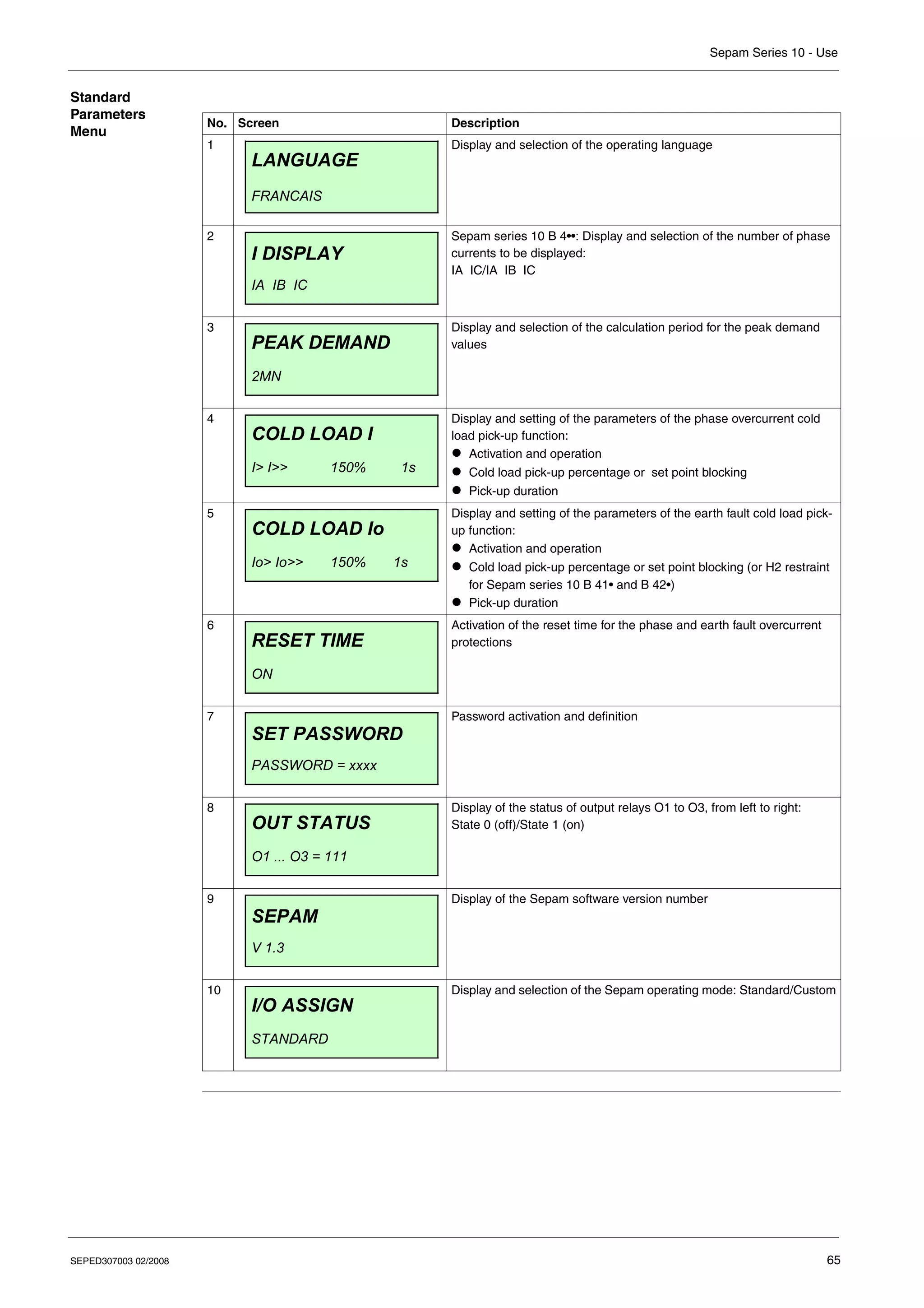
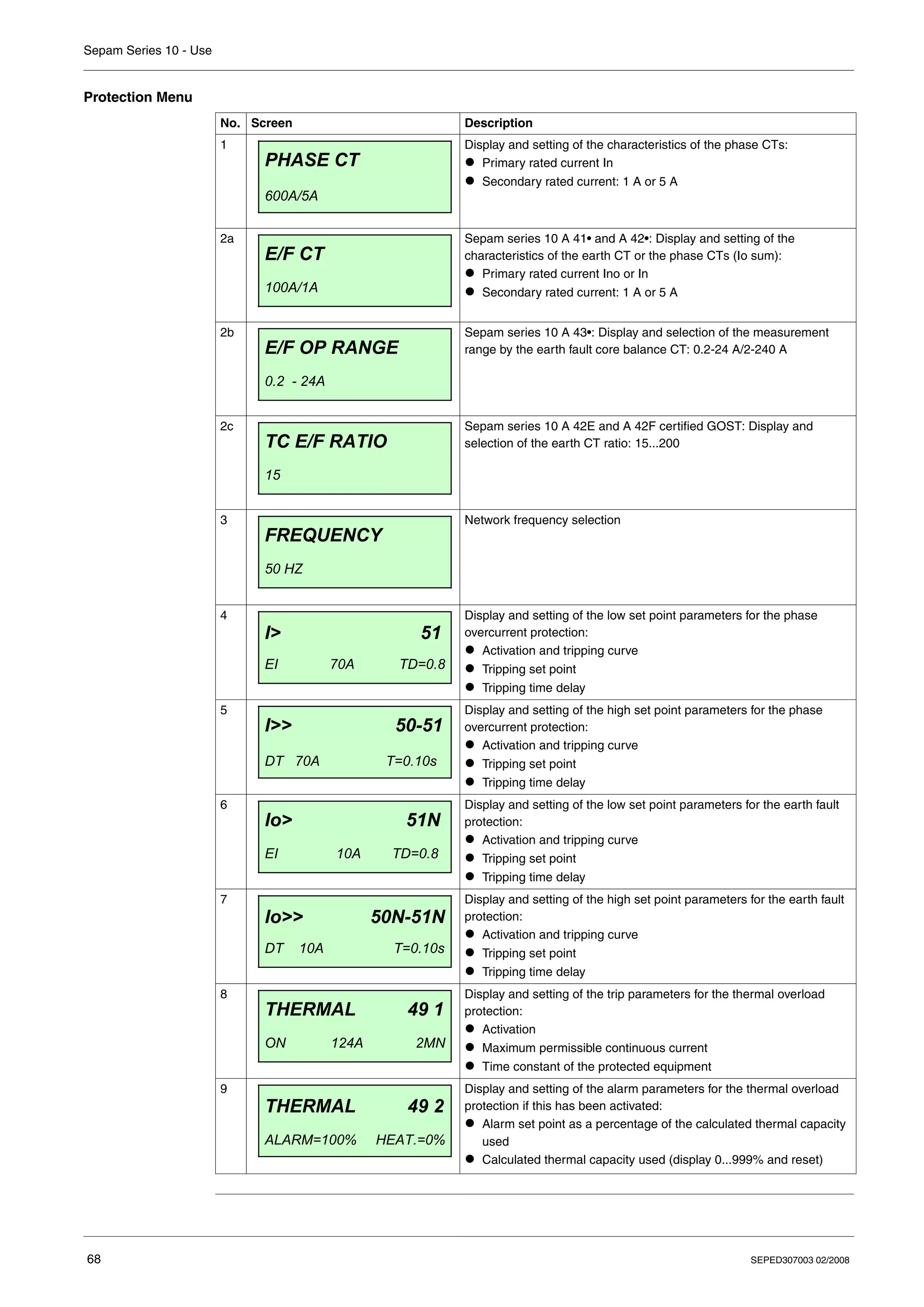
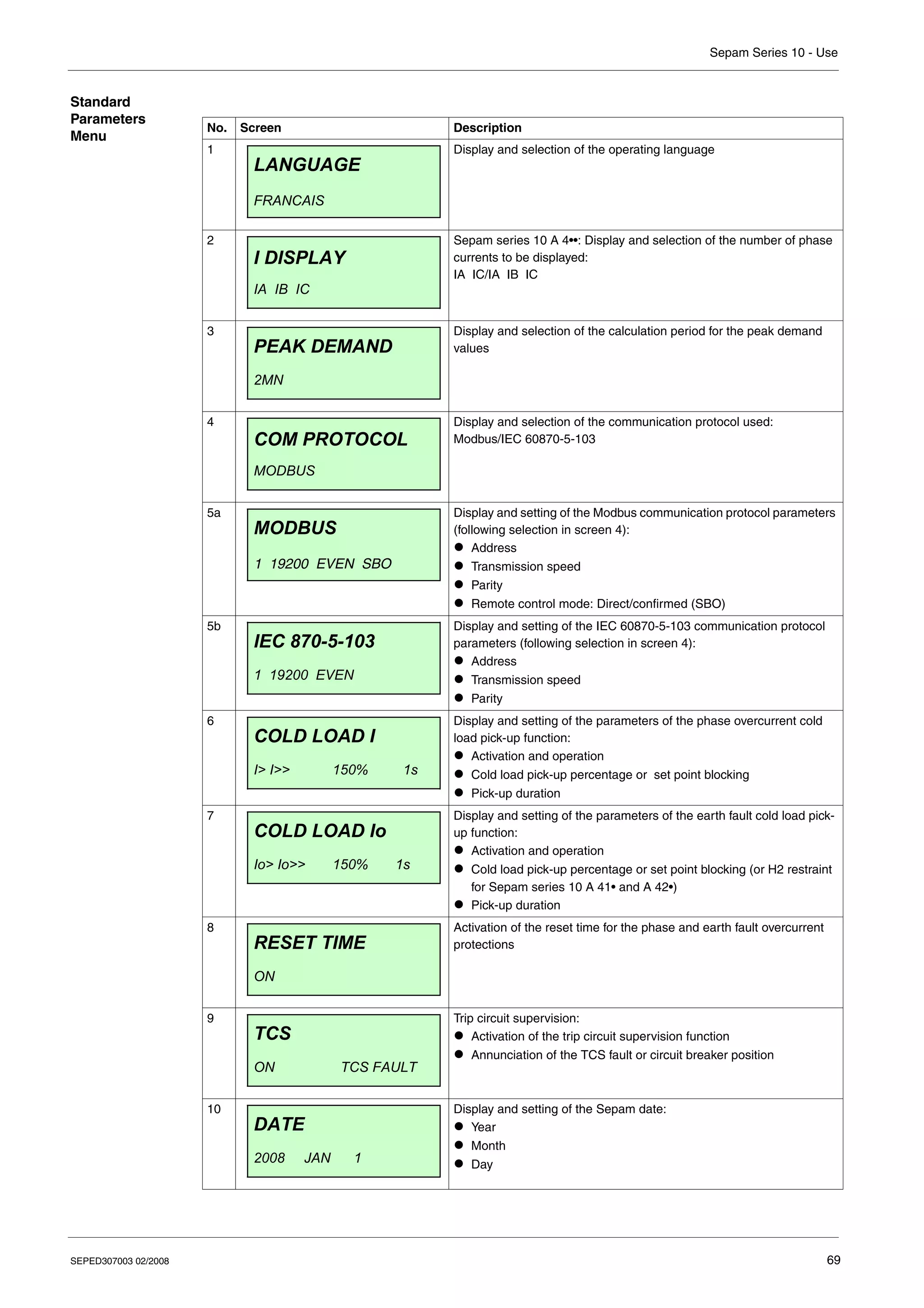
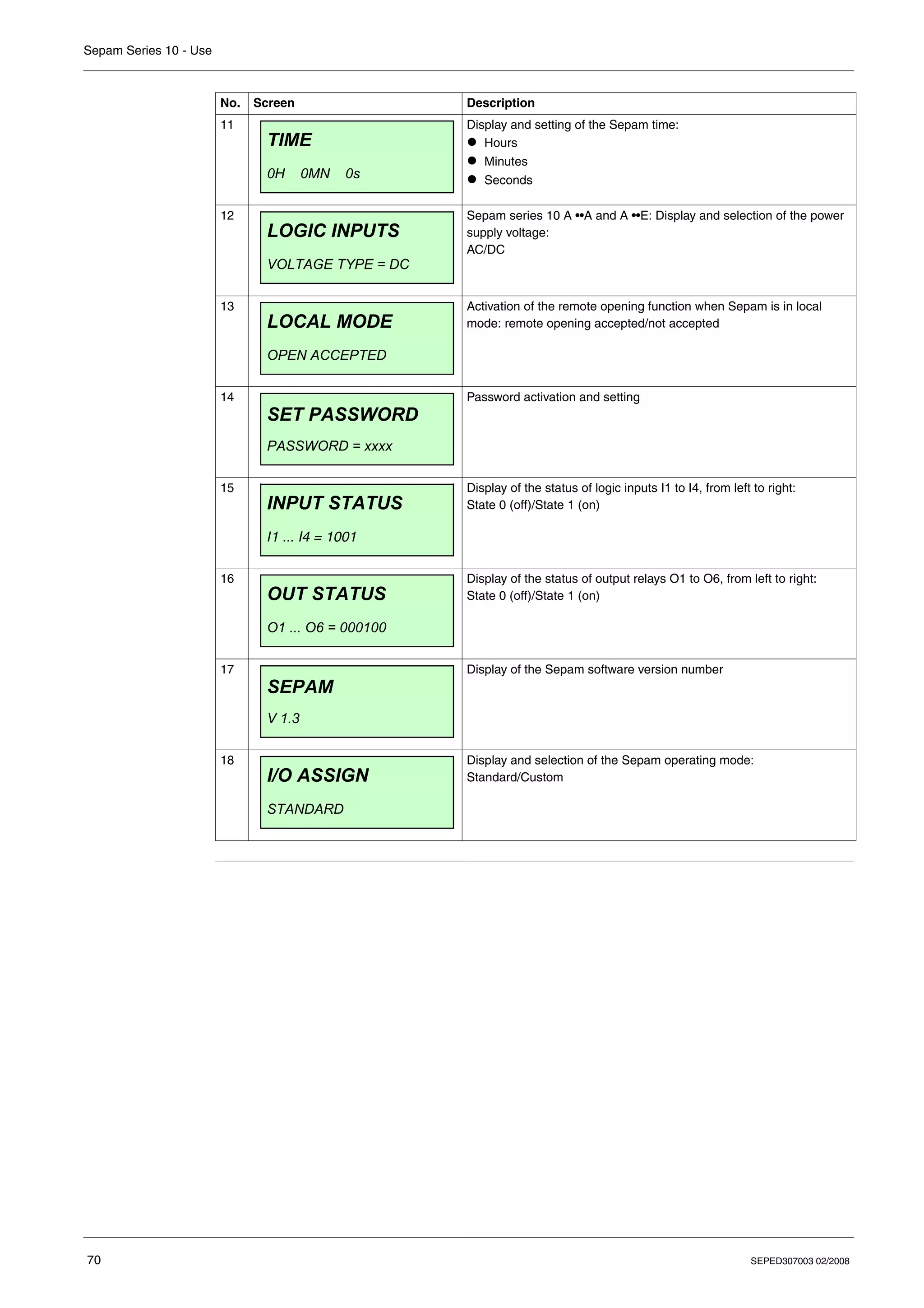
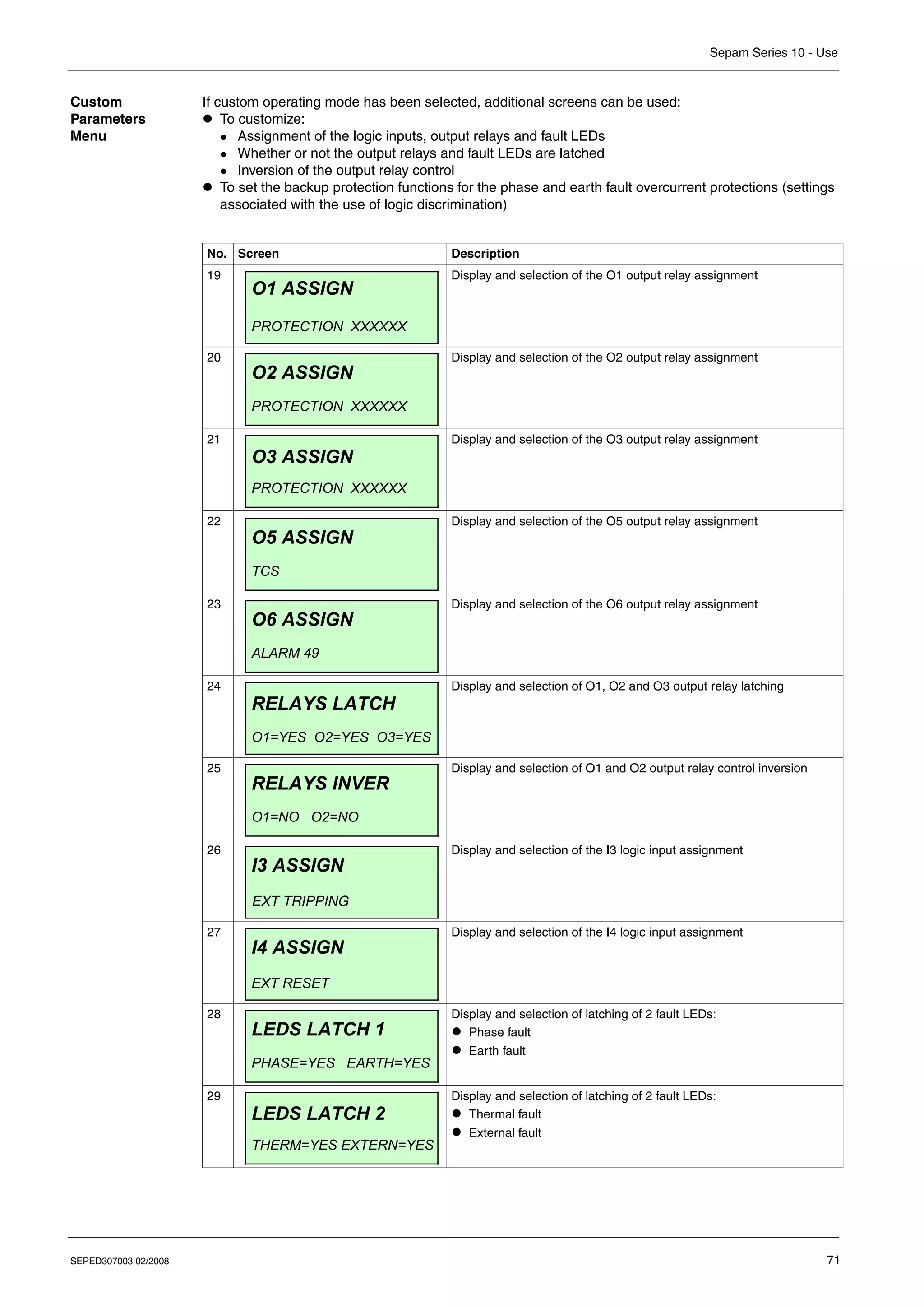
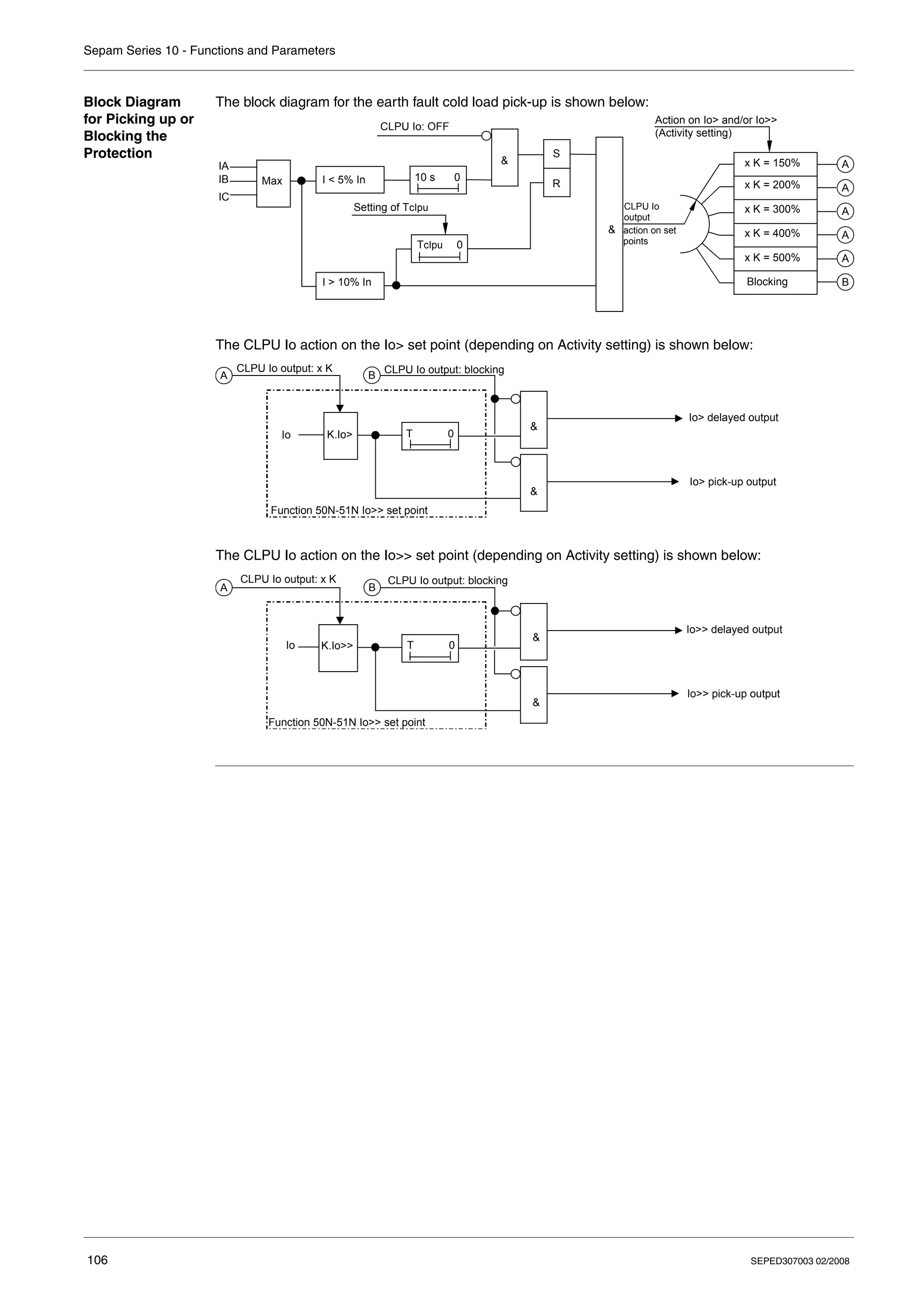
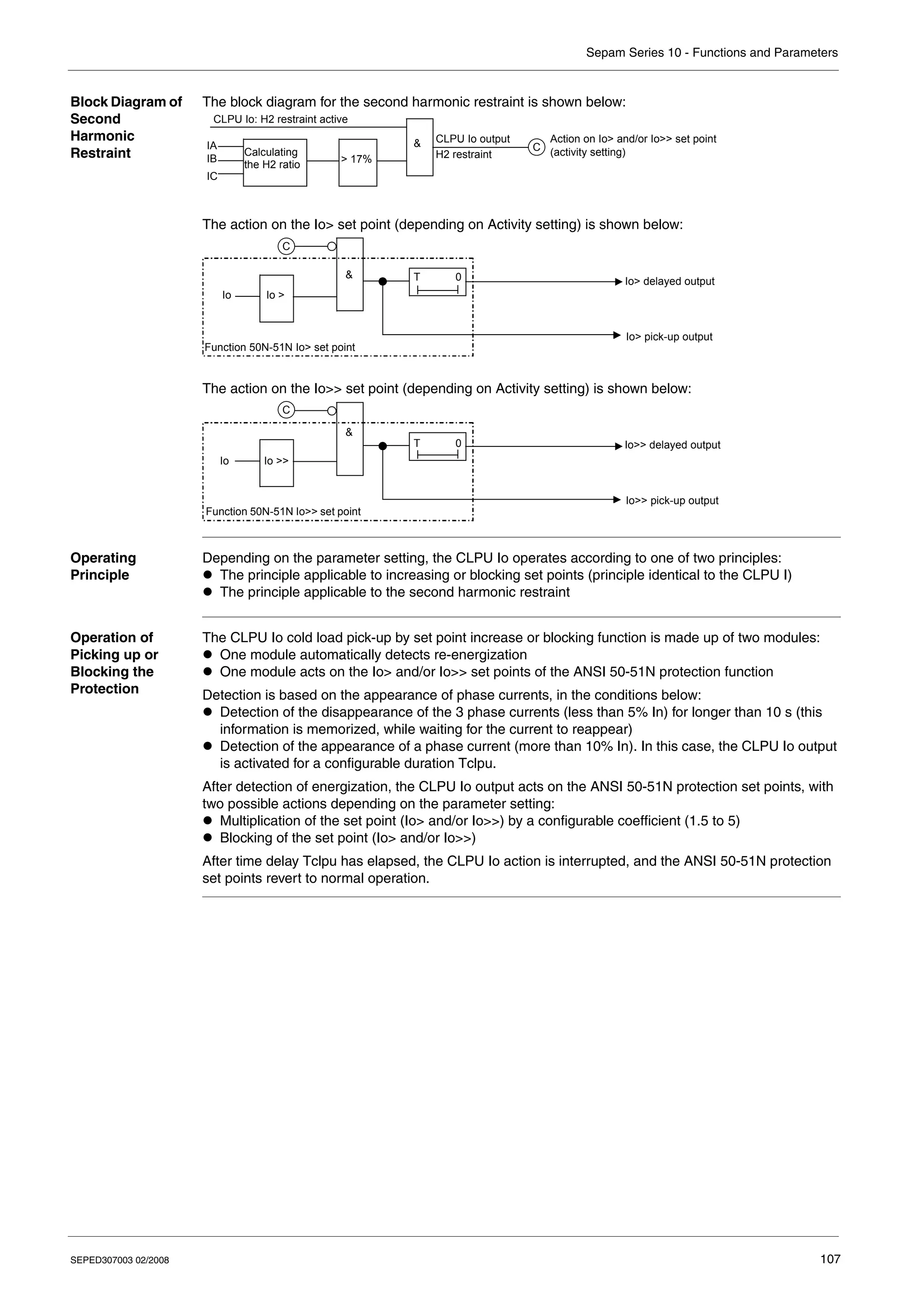
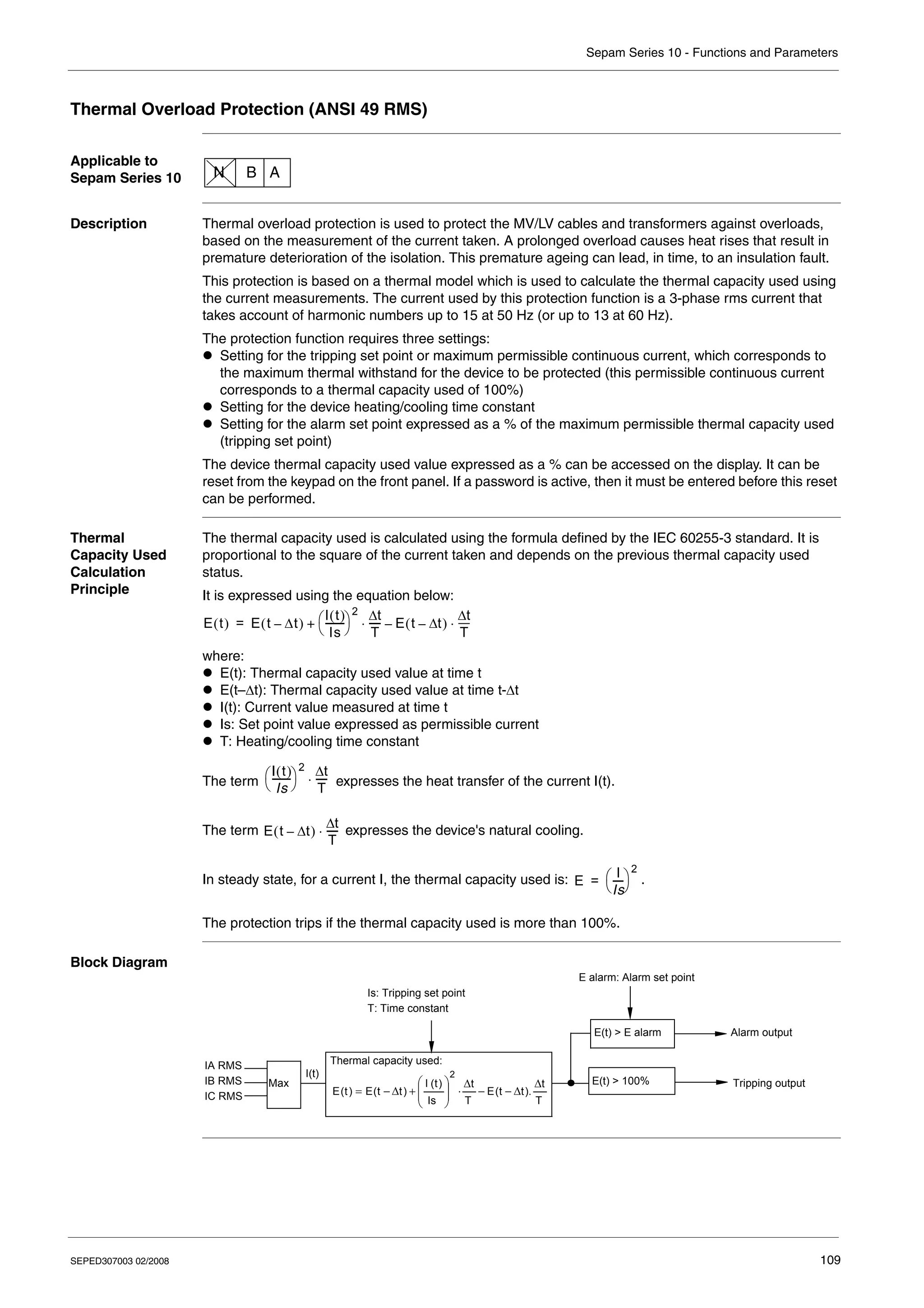
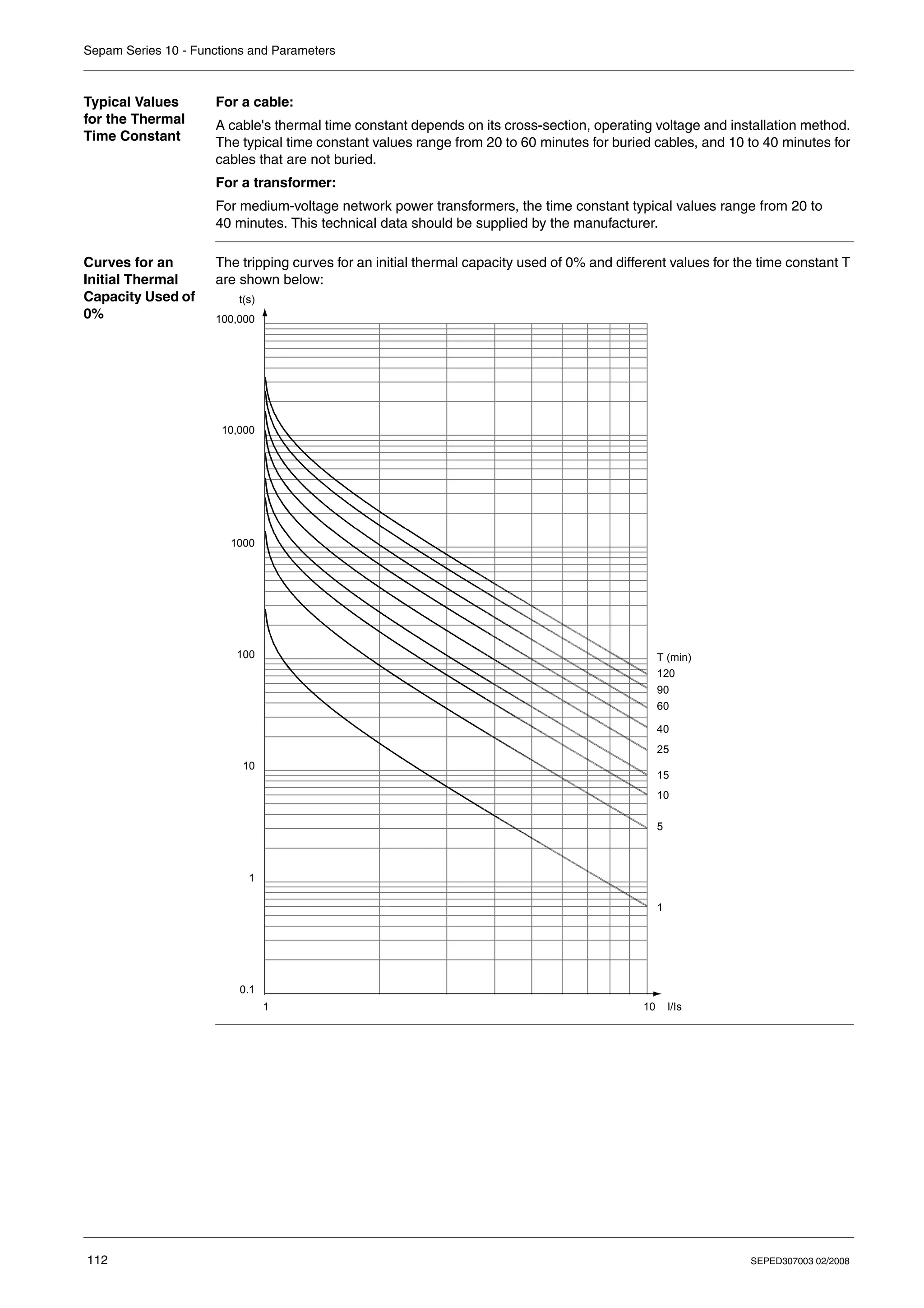
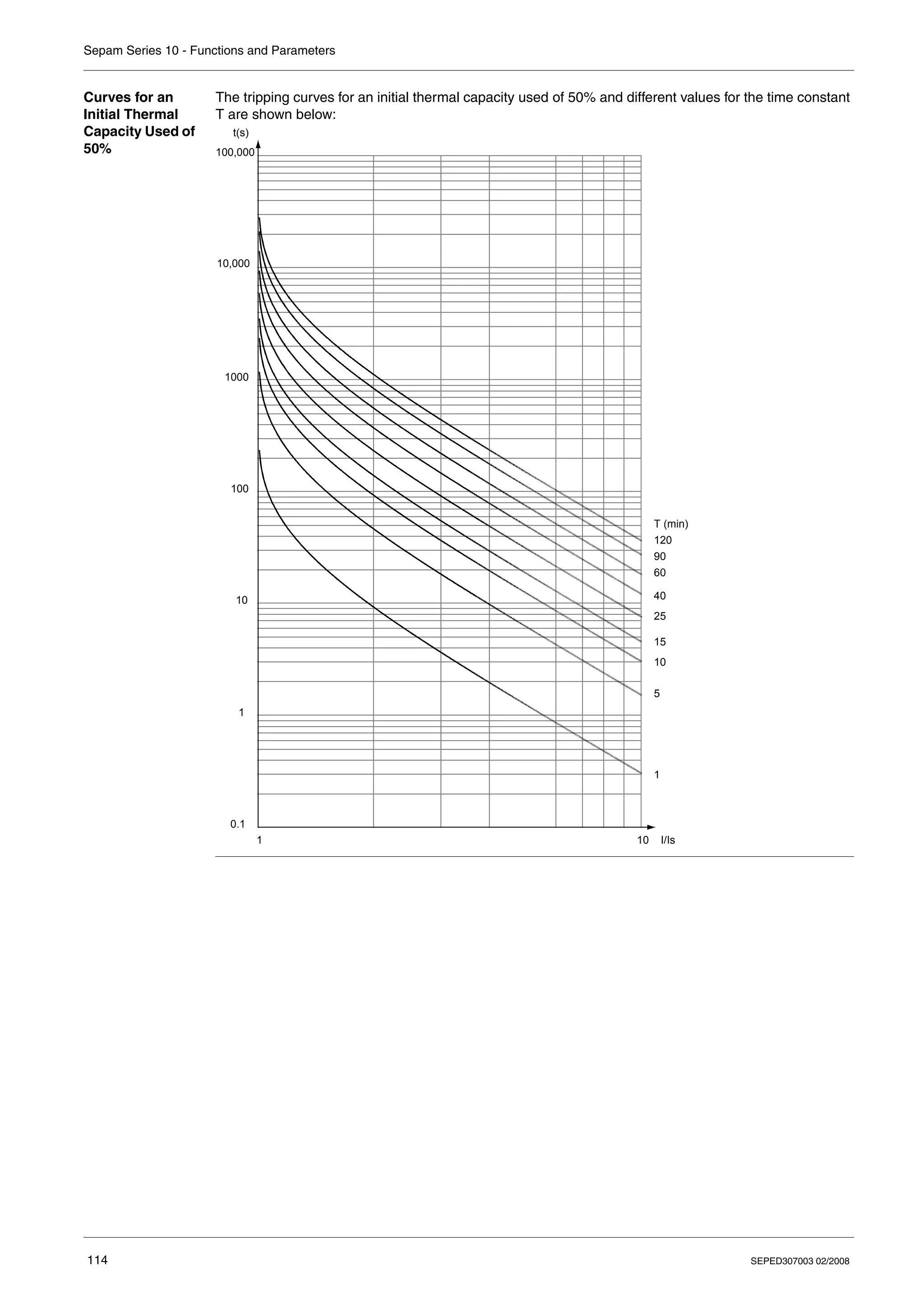
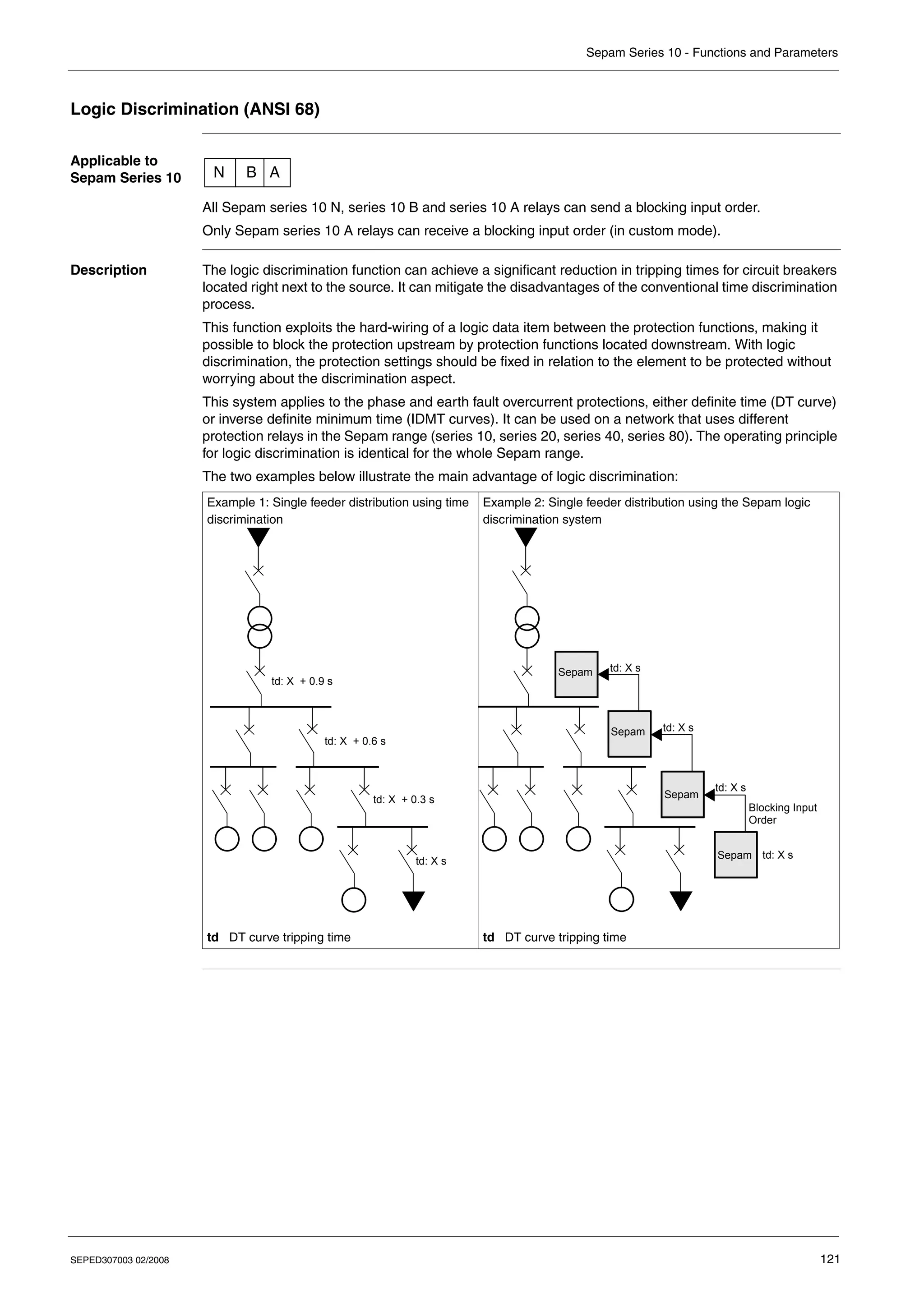
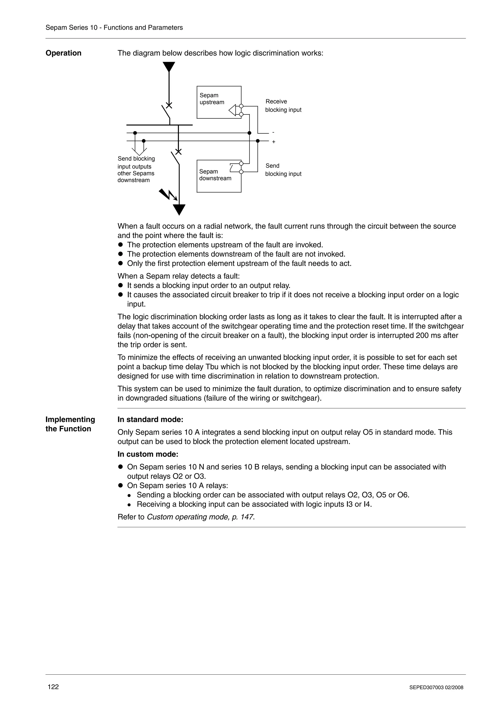
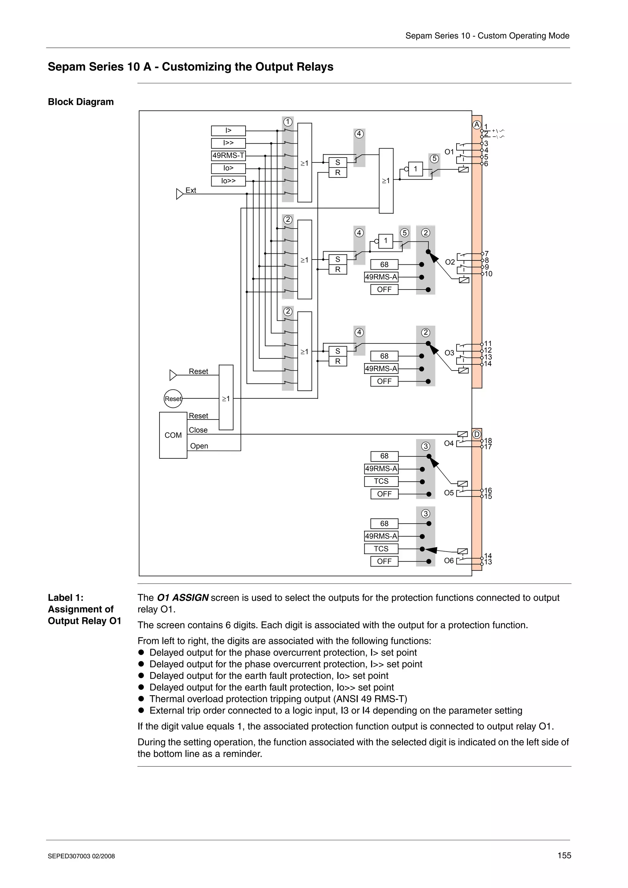
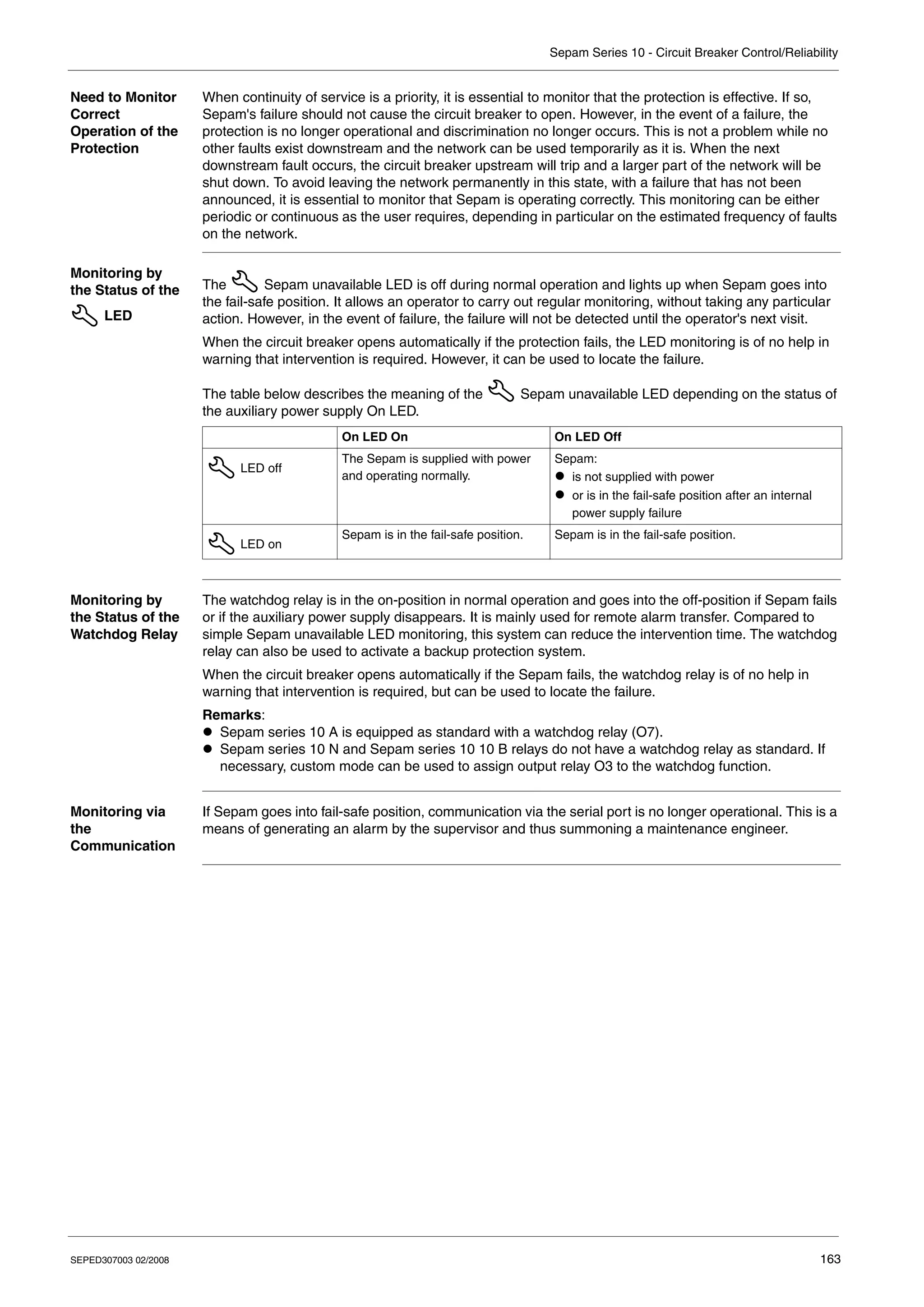
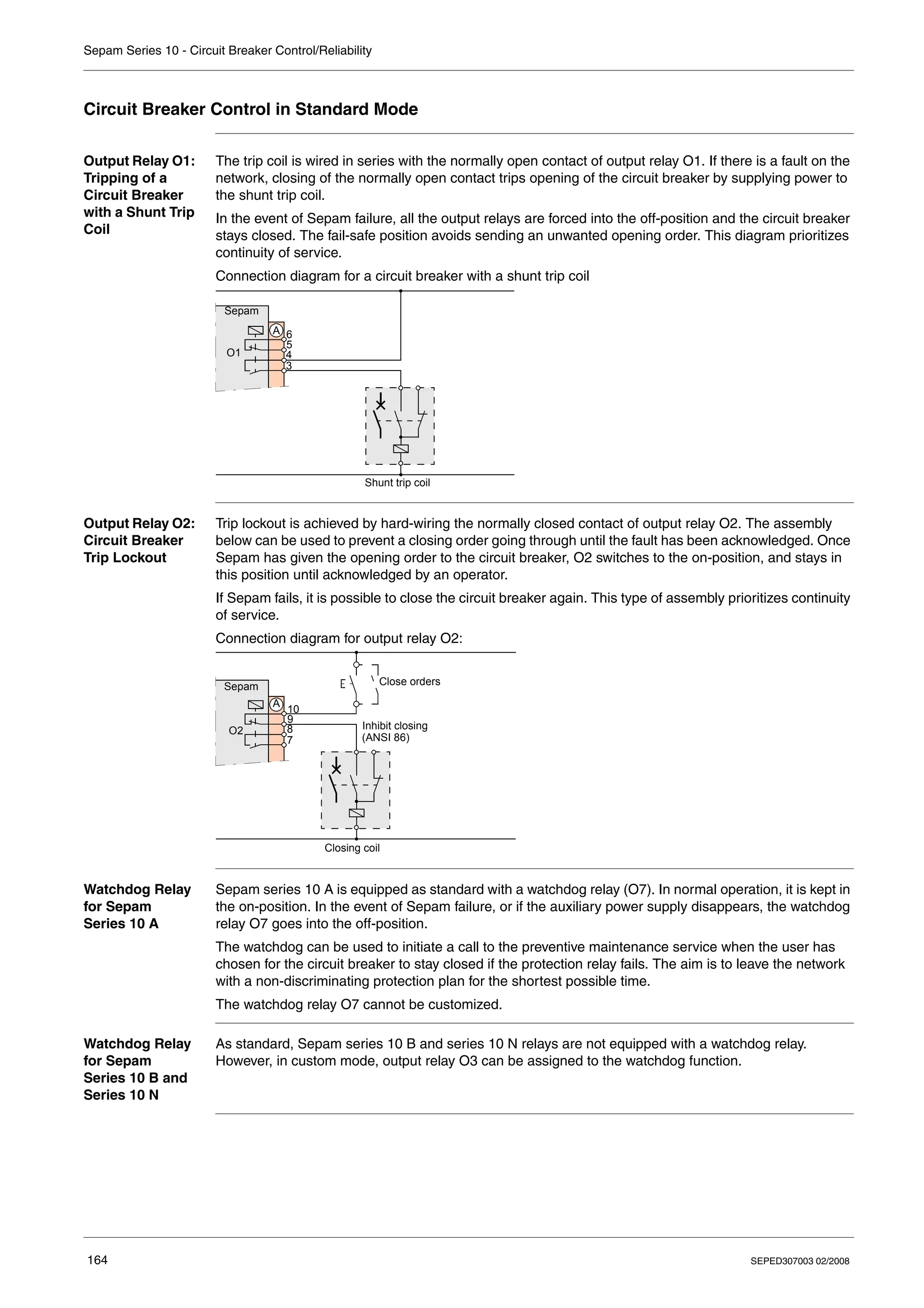
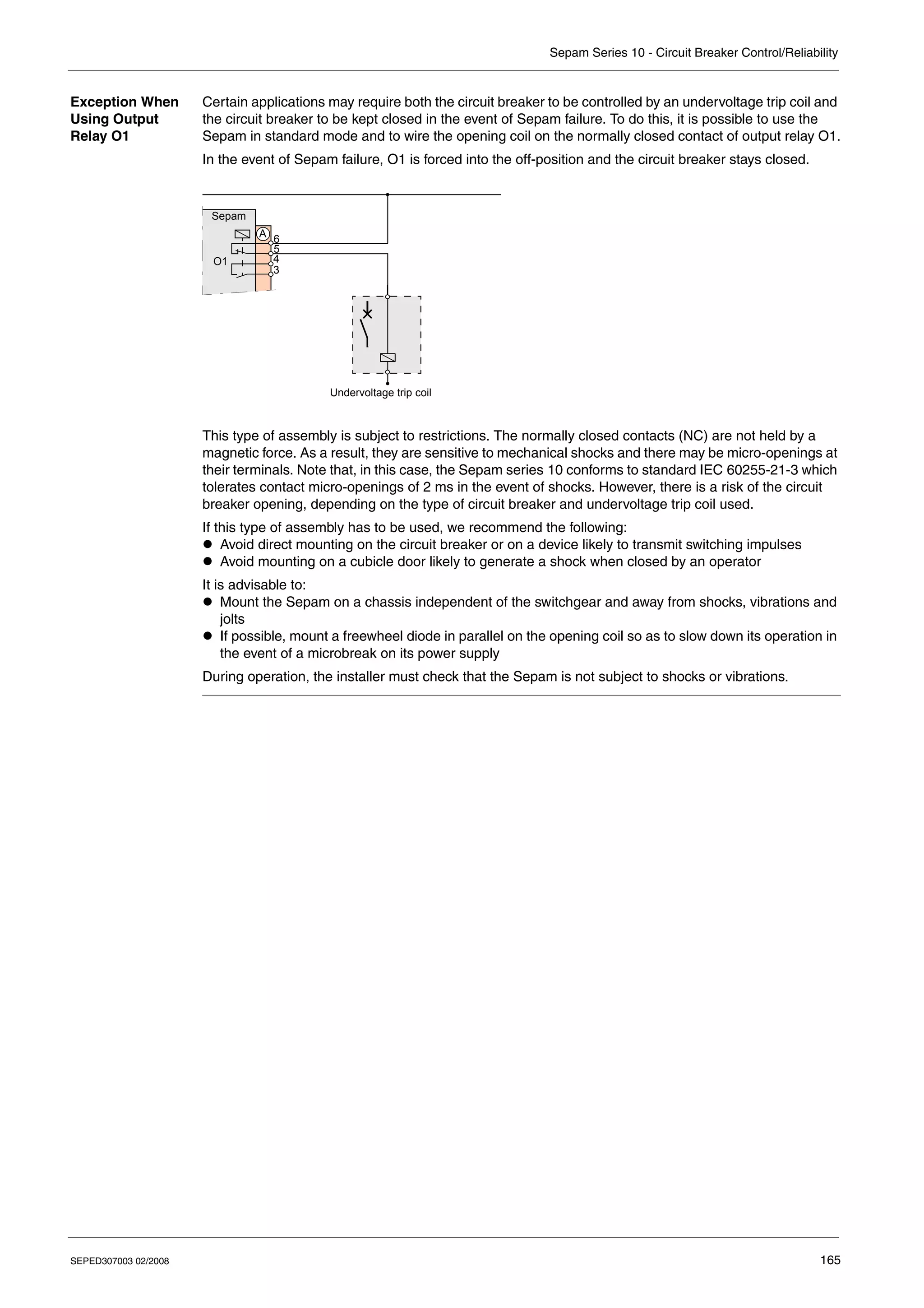
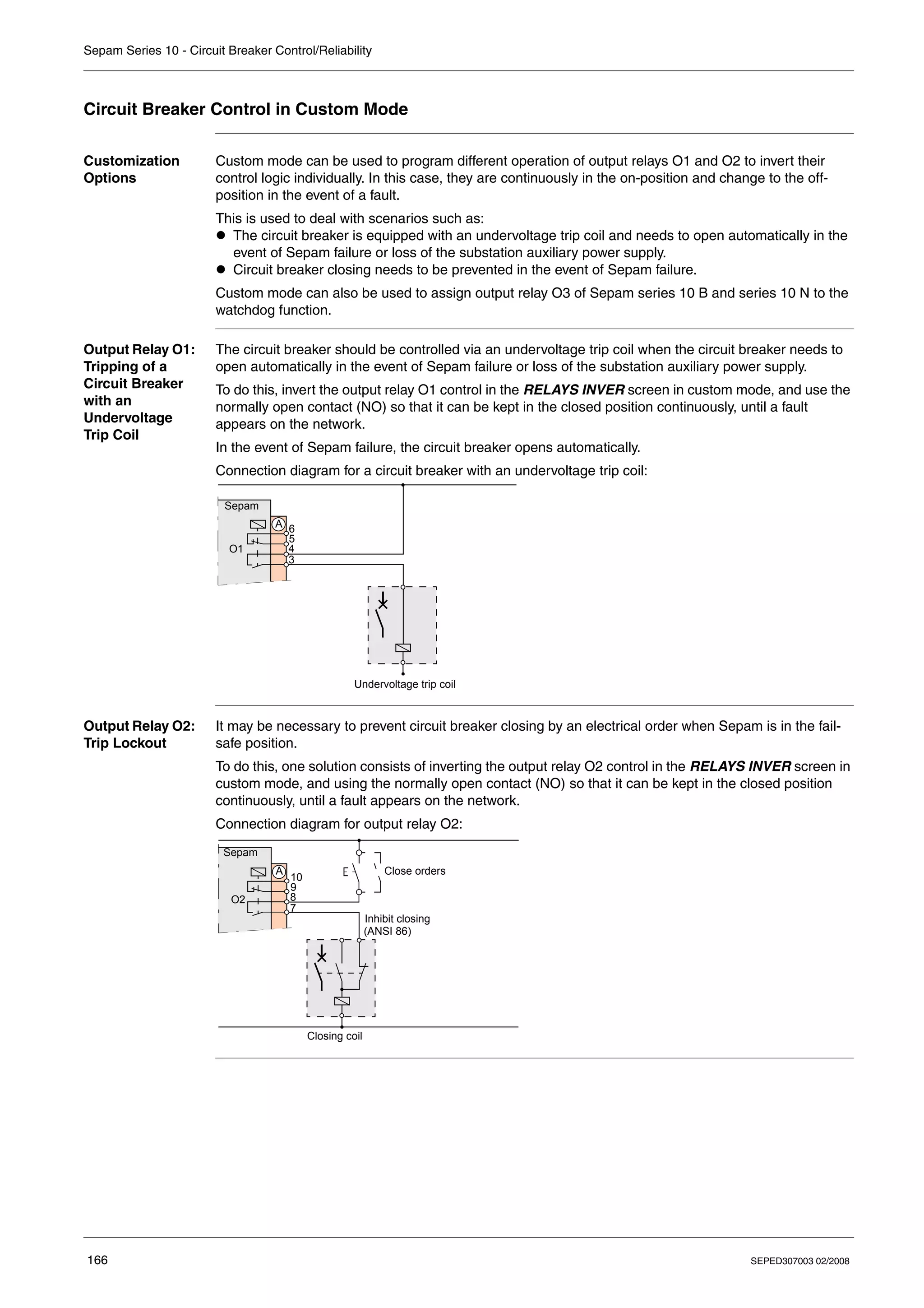
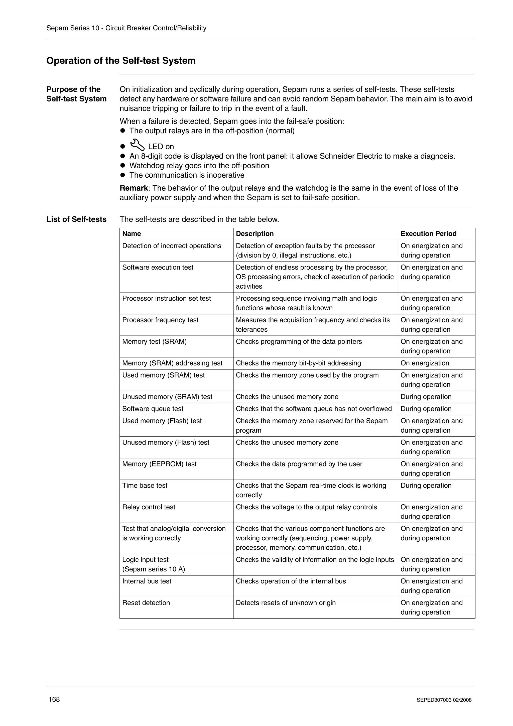
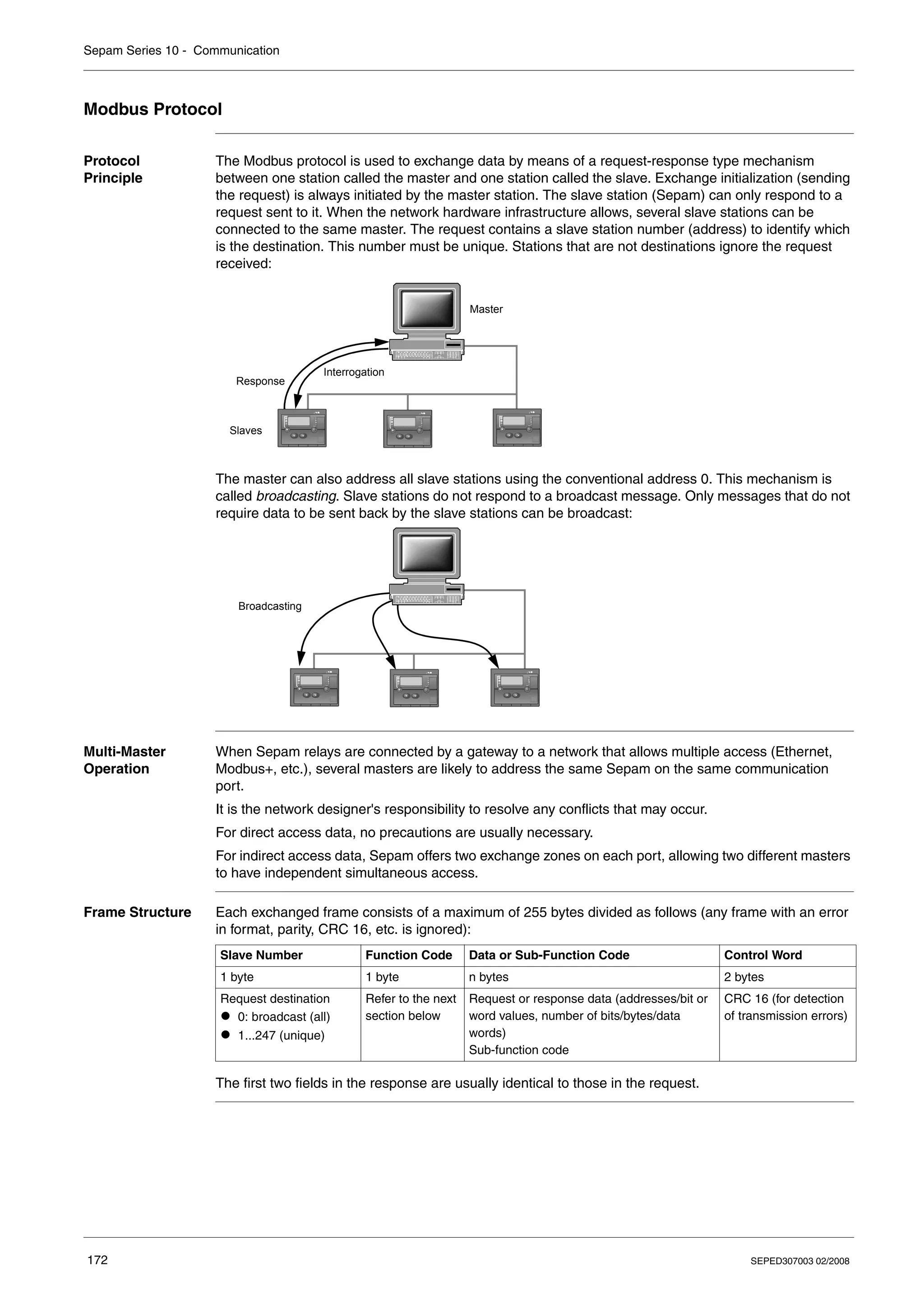
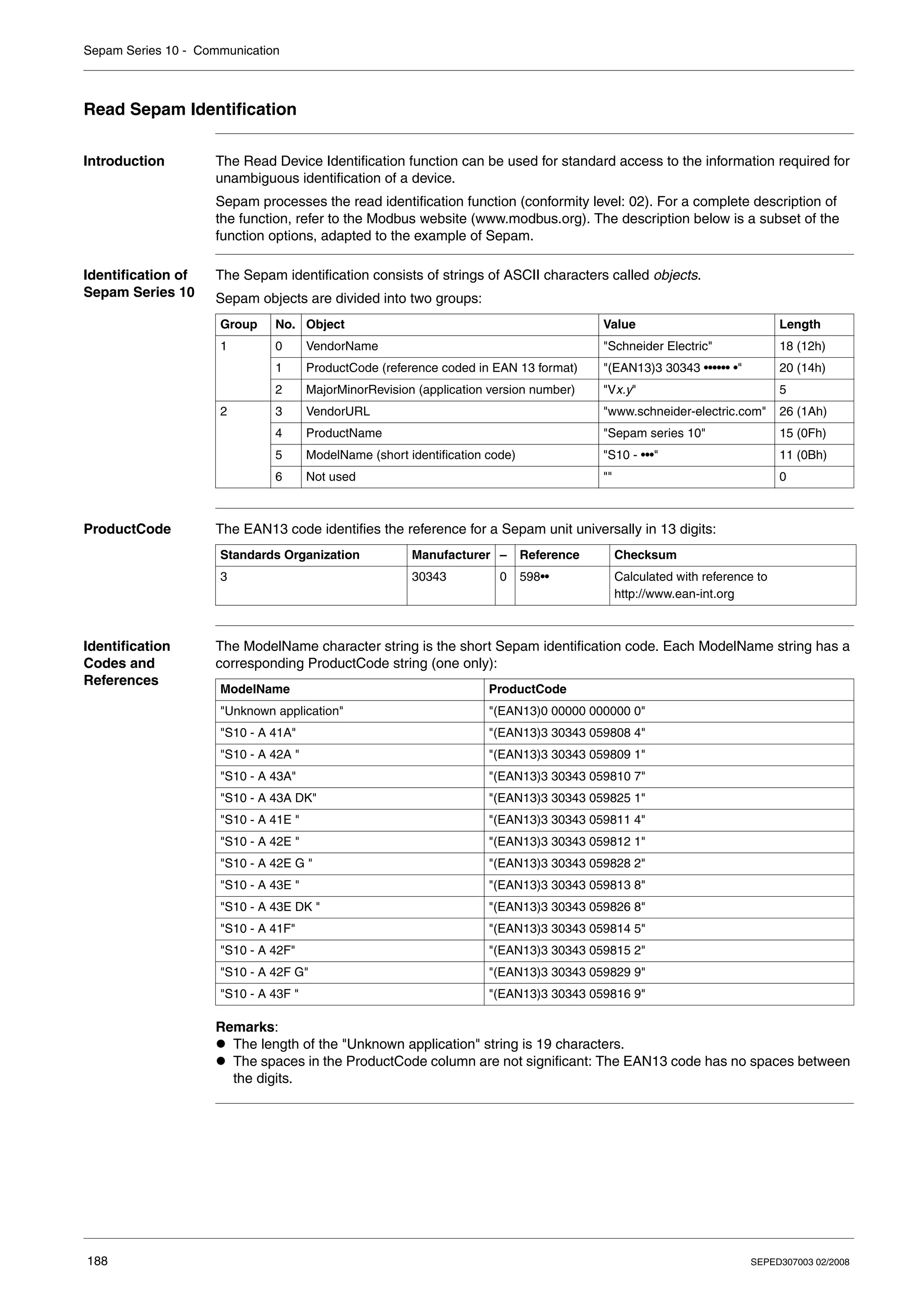
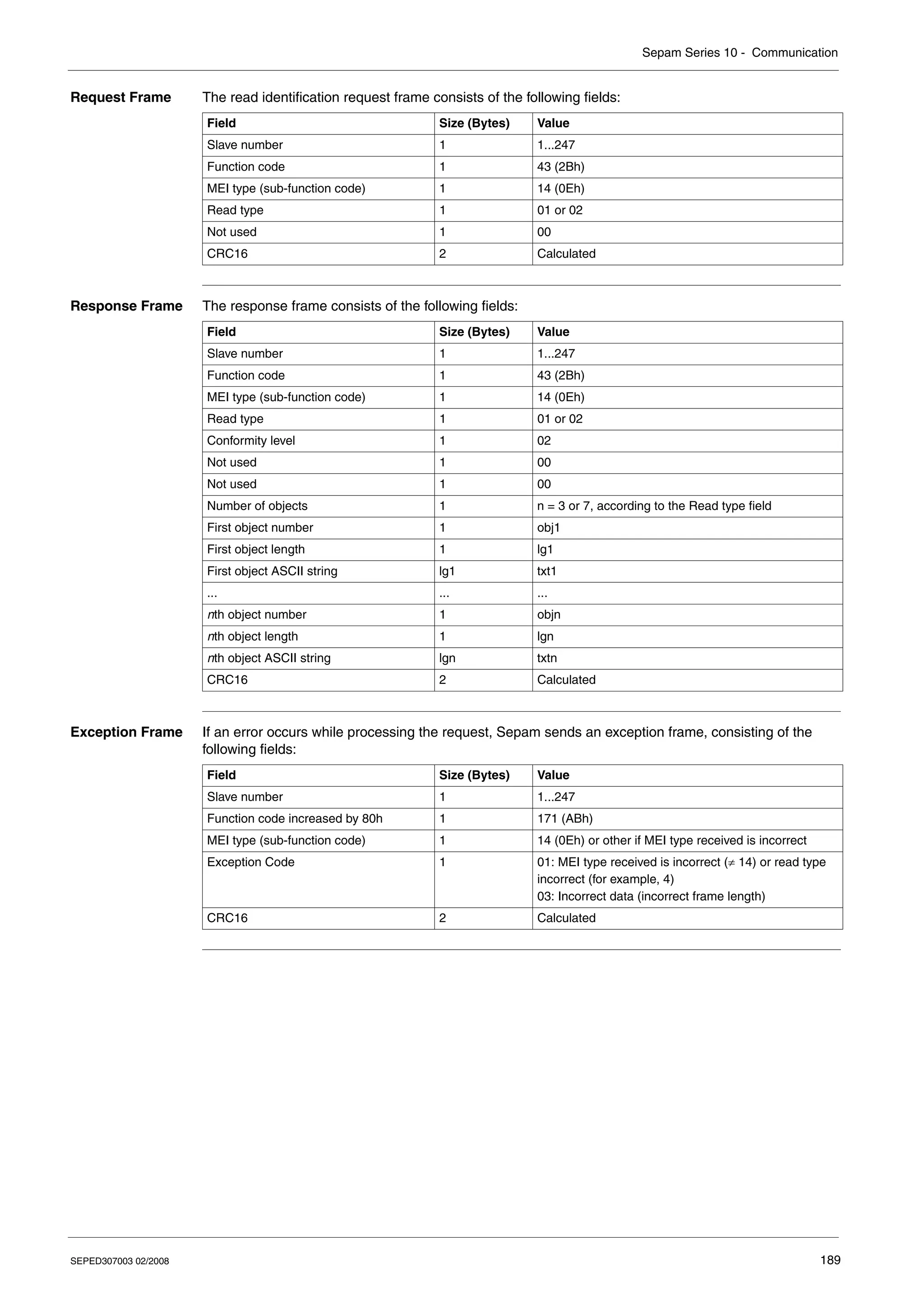
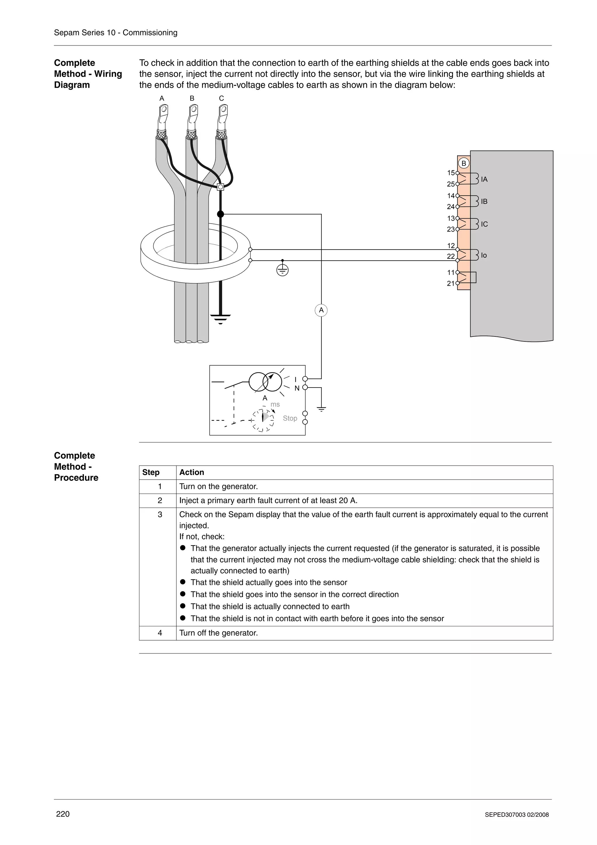
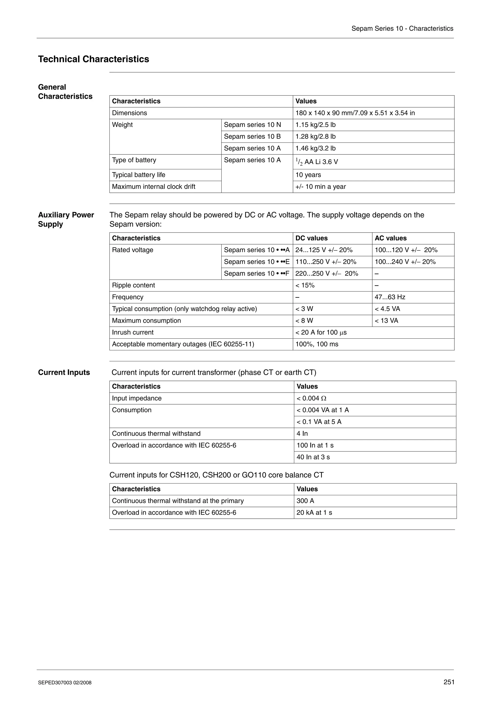
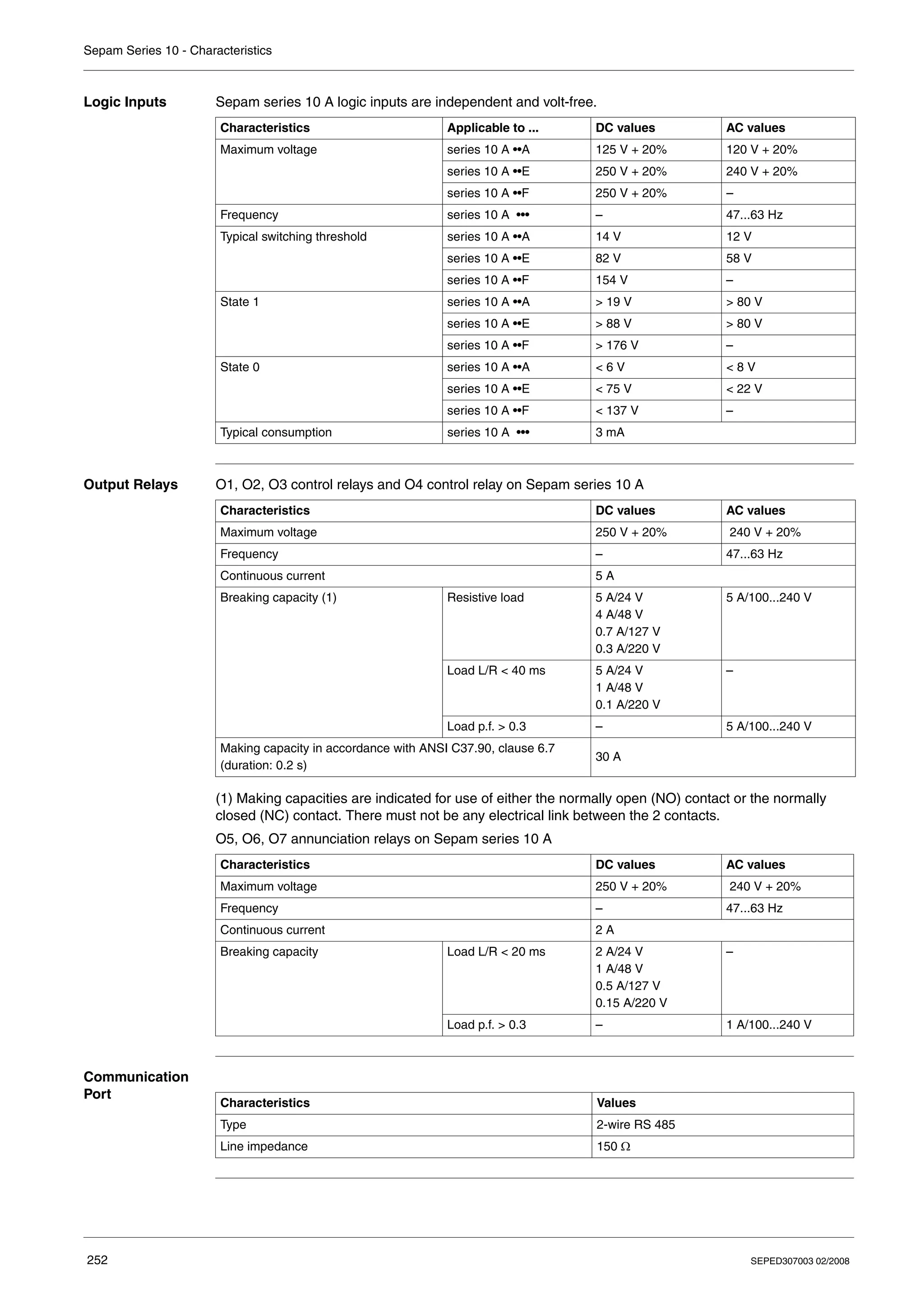
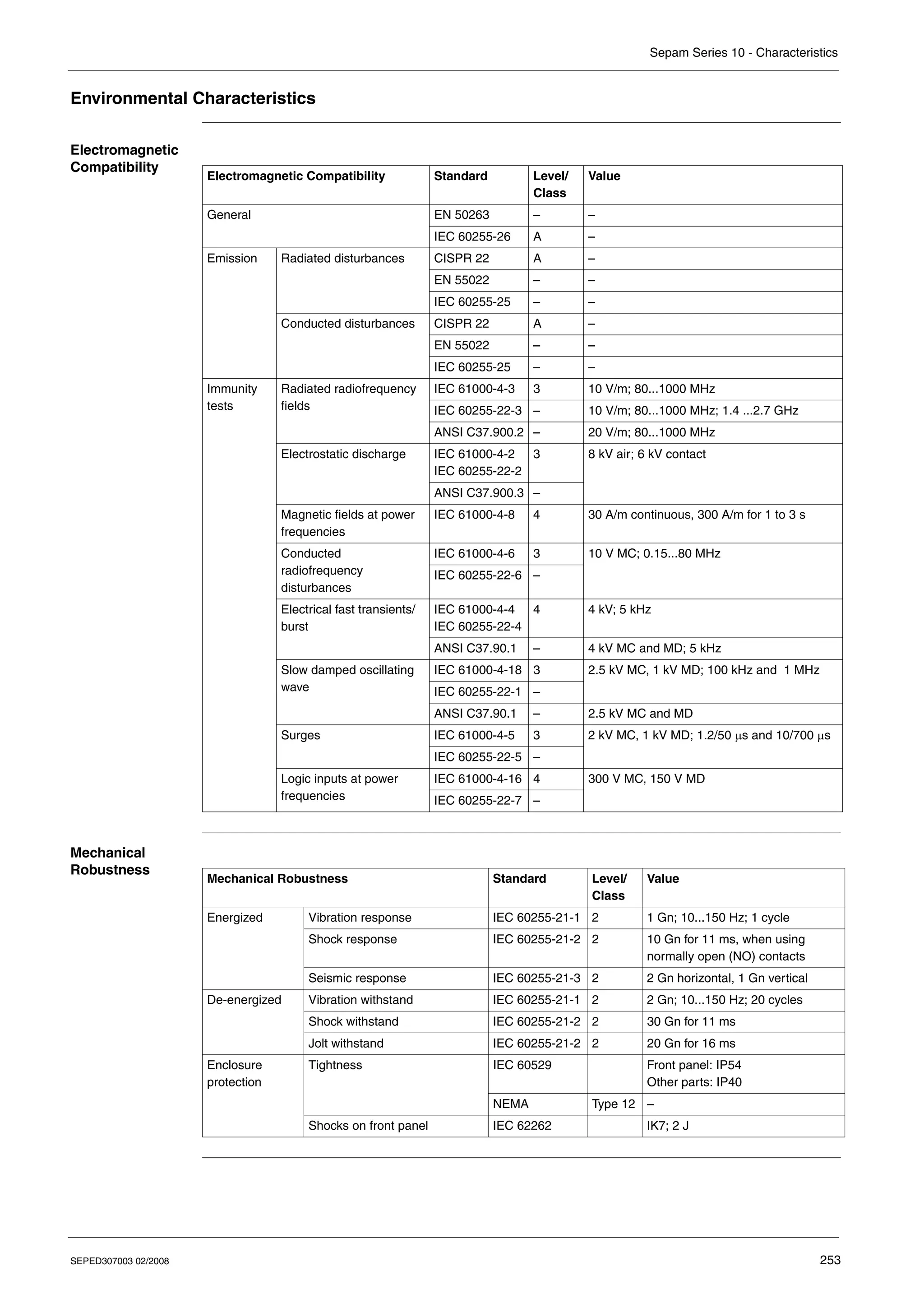
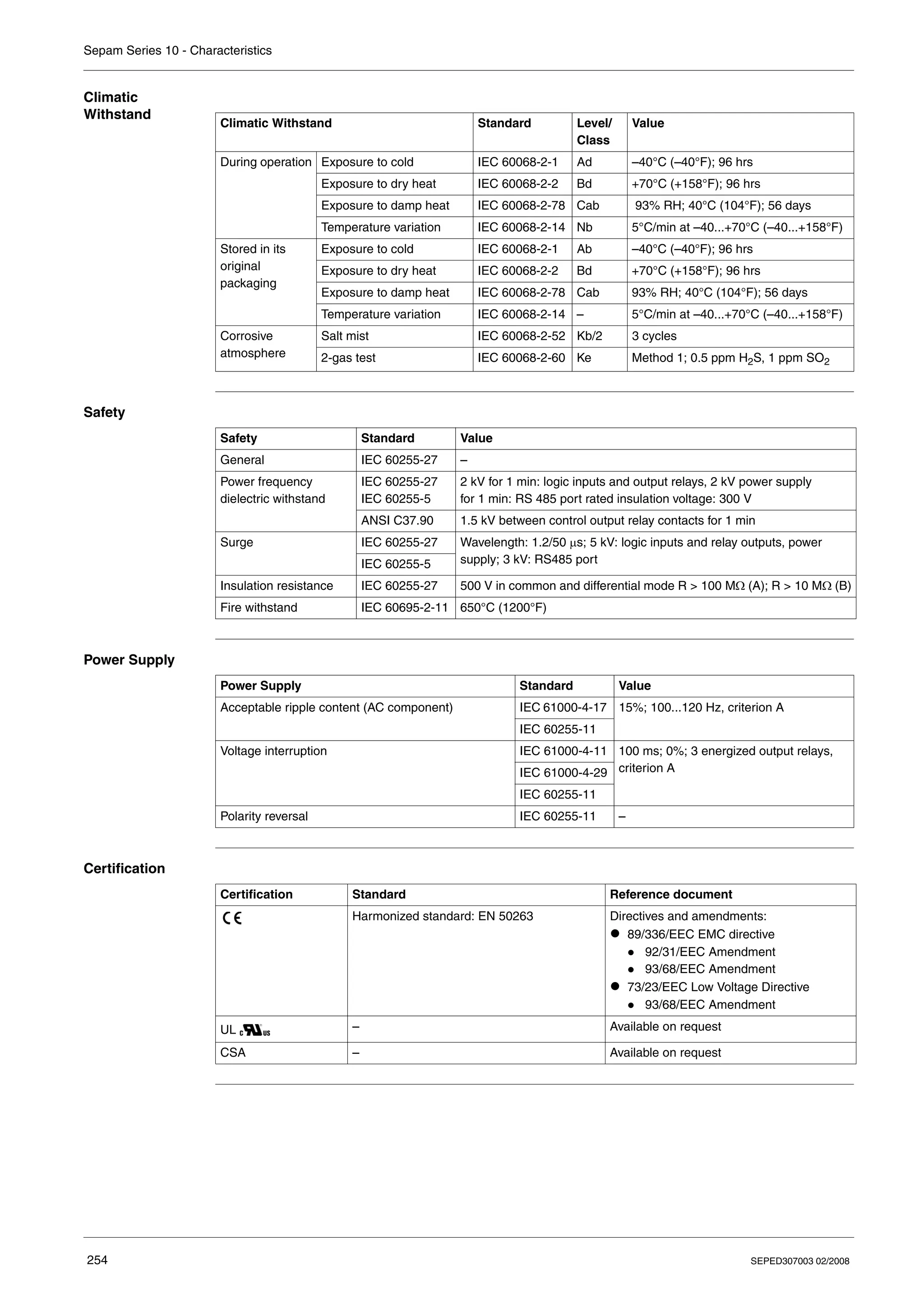
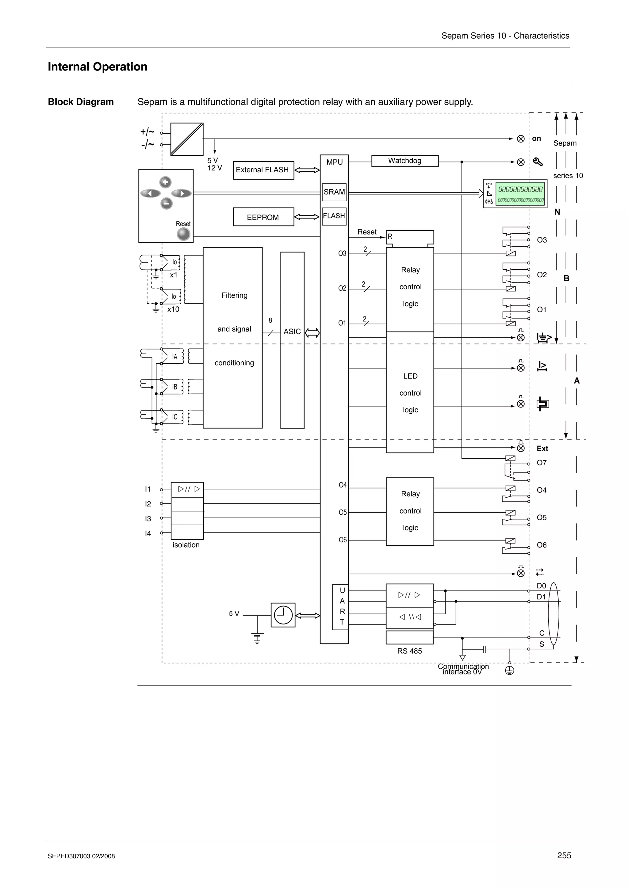
Electrical network protectionistribution élect
Sepam series 10
Reference manual
CÔNG TY CỔ PHẦN THIẾT BỊ ĐIỆN HOÀNG PHƯƠNG
ĐC: Số 10, ngõ 44, phố Võ Thị Sáu, P.Thanh Nhàn, Q.Hai Bà Trưng, TP. Hà Nội
MST: 0106798886
Tel: 024.3215.1322
Website: Hoangphuong.com.vn
Phone: 0944.240.317 / 0975.123.698 / 0961.008.858
Email: Codienhoangphuong@gmail.com
SEPED307003 02/2008 3
Table of Contents
Safety Information . . . . . . . . . . . . . . . . . . . . . . . . . . . . . . . . . . . . . . . . . . . . . . . . . .7
About the Book . . . . . . . . . . . . . . . . . . . . . . . . . . . . . . . . . . . . . . . . . . . . . . . . . . . . .9
Chapter 1 Presentation . . . . . . . . . . . . . . . . . . . . . . . . . . . . . . . . . . . . . . . . . . . . . . . . . . . . . .11
Introduction . . . . . . . . . . . . . . . . . . . . . . . . . . . . . . . . . . . . . . . . . . . . . . . . . . . . . . . . . . . . . . . . . . . . . . 12
Standard Operation. . . . . . . . . . . . . . . . . . . . . . . . . . . . . . . . . . . . . . . . . . . . . . . . . . . . . . . . . . . . . . . . 15
Identification . . . . . . . . . . . . . . . . . . . . . . . . . . . . . . . . . . . . . . . . . . . . . . . . . . . . . . . . . . . . . . . . . . . . . 18
Chapter 2 Installation. . . . . . . . . . . . . . . . . . . . . . . . . . . . . . . . . . . . . . . . . . . . . . . . . . . . . . . .21
Safety Precautions . . . . . . . . . . . . . . . . . . . . . . . . . . . . . . . . . . . . . . . . . . . . . . . . . . . . . . . . . . . . . . . . 22
Precautions . . . . . . . . . . . . . . . . . . . . . . . . . . . . . . . . . . . . . . . . . . . . . . . . . . . . . . . . . . . . . . . . . . . . . . 23
Equipment Receipt and Identification . . . . . . . . . . . . . . . . . . . . . . . . . . . . . . . . . . . . . . . . . . . . . . . . . . 24
Mounting/Assembly. . . . . . . . . . . . . . . . . . . . . . . . . . . . . . . . . . . . . . . . . . . . . . . . . . . . . . . . . . . . . . . . 25
Connectors . . . . . . . . . . . . . . . . . . . . . . . . . . . . . . . . . . . . . . . . . . . . . . . . . . . . . . . . . . . . . . . . . . . . . . 27
Connection Diagrams . . . . . . . . . . . . . . . . . . . . . . . . . . . . . . . . . . . . . . . . . . . . . . . . . . . . . . . . . . . . . . 30
Connecting Current Transformers (CTs) . . . . . . . . . . . . . . . . . . . . . . . . . . . . . . . . . . . . . . . . . . . . . . . . 38
Connecting a Core Balance CT. . . . . . . . . . . . . . . . . . . . . . . . . . . . . . . . . . . . . . . . . . . . . . . . . . . . . . . 40
Connecting the Logic Inputs and Output Relays . . . . . . . . . . . . . . . . . . . . . . . . . . . . . . . . . . . . . . . . . . 42
Connecting the Communication Port. . . . . . . . . . . . . . . . . . . . . . . . . . . . . . . . . . . . . . . . . . . . . . . . . . . 43
Dimensioning the CTs. . . . . . . . . . . . . . . . . . . . . . . . . . . . . . . . . . . . . . . . . . . . . . . . . . . . . . . . . . . . . . 44
CSH120, CSH200 and GO110 Core Balance CTs . . . . . . . . . . . . . . . . . . . . . . . . . . . . . . . . . . . . . . . . 46
Chapter 3 Use . . . . . . . . . . . . . . . . . . . . . . . . . . . . . . . . . . . . . . . . . . . . . . . . . . . . . . . . . . . . . .51
User-Machine Interface . . . . . . . . . . . . . . . . . . . . . . . . . . . . . . . . . . . . . . . . . . . . . . . . . . . . . . . . . . . . . 52
Operation. . . . . . . . . . . . . . . . . . . . . . . . . . . . . . . . . . . . . . . . . . . . . . . . . . . . . . . . . . . . . . . . . . . . . . . . 54
Setting . . . . . . . . . . . . . . . . . . . . . . . . . . . . . . . . . . . . . . . . . . . . . . . . . . . . . . . . . . . . . . . . . . . . . . . . . . 56
List of Sepam Series 10 N Screens . . . . . . . . . . . . . . . . . . . . . . . . . . . . . . . . . . . . . . . . . . . . . . . . . . . 60
List of Sepam Series 10 B Screens . . . . . . . . . . . . . . . . . . . . . . . . . . . . . . . . . . . . . . . . . . . . . . . . . . . 63
List of Sepam Series 10 A Screens . . . . . . . . . . . . . . . . . . . . . . . . . . . . . . . . . . . . . . . . . . . . . . . . . . . 67
Chapter 4 Functions and parameters. . . . . . . . . . . . . . . . . . . . . . . . . . . . . . . . . . . . . . . . . . .73
General Principle. . . . . . . . . . . . . . . . . . . . . . . . . . . . . . . . . . . . . . . . . . . . . . . . . . . . . . . . . . . . . . . . . . 74
Definition of Symbols. . . . . . . . . . . . . . . . . . . . . . . . . . . . . . . . . . . . . . . . . . . . . . . . . . . . . . . . . . . . . . . 75
Phase CT Ratio. . . . . . . . . . . . . . . . . . . . . . . . . . . . . . . . . . . . . . . . . . . . . . . . . . . . . . . . . . . . . . . . . . . 77
Earth CT Ratio or Core balance CT Rating. . . . . . . . . . . . . . . . . . . . . . . . . . . . . . . . . . . . . . . . . . . . . . 78
Network Frequency . . . . . . . . . . . . . . . . . . . . . . . . . . . . . . . . . . . . . . . . . . . . . . . . . . . . . . . . . . . . . . . . 79
Phase Overcurrent Protection (ANSI 50-51) . . . . . . . . . . . . . . . . . . . . . . . . . . . . . . . . . . . . . . . . . . . . . 80
Earth Fault Protection (ANSI 50N-51N) . . . . . . . . . . . . . . . . . . . . . . . . . . . . . . . . . . . . . . . . . . . . . . . . 84
Overcurrent Protection Tripping Curves . . . . . . . . . . . . . . . . . . . . . . . . . . . . . . . . . . . . . . . . . . . . . . . . 90
Phase Overcurrent Cold Load Pick-Up (Cold Load Pick-Up I) . . . . . . . . . . . . . . . . . . . . . . . . . . . . . . 102
Earth Fault Cold Load Pick-Up (Cold Load Pick-Up Io). . . . . . . . . . . . . . . . . . . . . . . . . . . . . . . . . . . . 105
Thermal Overload Protection (ANSI 49 RMS) . . . . . . . . . . . . . . . . . . . . . . . . . . . . . . . . . . . . . . . . . . 109
Circuit Breaker Control . . . . . . . . . . . . . . . . . . . . . . . . . . . . . . . . . . . . . . . . . . . . . . . . . . . . . . . . . . . . 117
External Trip . . . . . . . . . . . . . . . . . . . . . . . . . . . . . . . . . . . . . . . . . . . . . . . . . . . . . . . . . . . . . . . . . . . . 120
Logic Discrimination (ANSI 68) . . . . . . . . . . . . . . . . . . . . . . . . . . . . . . . . . . . . . . . . . . . . . . . . . . . . . . 121
Phase Current Measurement . . . . . . . . . . . . . . . . . . . . . . . . . . . . . . . . . . . . . . . . . . . . . . . . . . . . . . . 125
Earth Fault Current Measurement. . . . . . . . . . . . . . . . . . . . . . . . . . . . . . . . . . . . . . . . . . . . . . . . . . . . 126
Phase Peak Demand Current Values . . . . . . . . . . . . . . . . . . . . . . . . . . . . . . . . . . . . . . . . . . . . . . . . . 127
Last Fault Record . . . . . . . . . . . . . . . . . . . . . . . . . . . . . . . . . . . . . . . . . . . . . . . . . . . . . . . . . . . . . . . . 128
Time-Tagged Record of Last 5 Events . . . . . . . . . . . . . . . . . . . . . . . . . . . . . . . . . . . . . . . . . . . . . . . . 129
Operating Language . . . . . . . . . . . . . . . . . . . . . . . . . . . . . . . . . . . . . . . . . . . . . . . . . . . . . . . . . . . . . . 130
Number of Phase Currents Displayed. . . . . . . . . . . . . . . . . . . . . . . . . . . . . . . . . . . . . . . . . . . . . . . . . 131
Communication . . . . . . . . . . . . . . . . . . . . . . . . . . . . . . . . . . . . . . . . . . . . . . . . . . . . . . . . . . . . . . . . . . 132
Trip Circuit Supervision (TCS). . . . . . . . . . . . . . . . . . . . . . . . . . . . . . . . . . . . . . . . . . . . . . . . . . . . . . . 135
Date and Time. . . . . . . . . . . . . . . . . . . . . . . . . . . . . . . . . . . . . . . . . . . . . . . . . . . . . . . . . . . . . . . . . . . 137
4 SEPED307003 02/2008
Voltage Applied to the Logic Inputs . . . . . . . . . . . . . . . . . . . . . . . . . . . . . . . . . . . . . . . . . . . . . . . . . . . 138
Operation of the Local/Remote Check. . . . . . . . . . . . . . . . . . . . . . . . . . . . . . . . . . . . . . . . . . . . . . . . . 139
Password . . . . . . . . . . . . . . . . . . . . . . . . . . . . . . . . . . . . . . . . . . . . . . . . . . . . . . . . . . . . . . . . . . . . . . . 140
Display the Status of the Logic Inputs . . . . . . . . . . . . . . . . . . . . . . . . . . . . . . . . . . . . . . . . . . . . . . . . . 141
Display the Status of the Output Relays . . . . . . . . . . . . . . . . . . . . . . . . . . . . . . . . . . . . . . . . . . . . . . . 142
Watchdog Relay. . . . . . . . . . . . . . . . . . . . . . . . . . . . . . . . . . . . . . . . . . . . . . . . . . . . . . . . . . . . . . . . . . 143
Indicator LEDs on the Front Panel . . . . . . . . . . . . . . . . . . . . . . . . . . . . . . . . . . . . . . . . . . . . . . . . . . . . 144
Fault Acknowledgement. . . . . . . . . . . . . . . . . . . . . . . . . . . . . . . . . . . . . . . . . . . . . . . . . . . . . . . . . . . . 146
Chapter 5 Custom operating mode . . . . . . . . . . . . . . . . . . . . . . . . . . . . . . . . . . . . . . . . . . . 147
Introduction . . . . . . . . . . . . . . . . . . . . . . . . . . . . . . . . . . . . . . . . . . . . . . . . . . . . . . . . . . . . . . . . . . . . . 148
Sepam Series 10 N - Customizing the Output Relays. . . . . . . . . . . . . . . . . . . . . . . . . . . . . . . . . . . . . 149
Sepam Series 10 N - Customizing the Fault LED . . . . . . . . . . . . . . . . . . . . . . . . . . . . . . . . . . . . . . . . 151
Sepam Series 10 B - Customizing the Output Relays . . . . . . . . . . . . . . . . . . . . . . . . . . . . . . . . . . . . . 152
Sepam Series 10 B - Customizing the Fault LEDs . . . . . . . . . . . . . . . . . . . . . . . . . . . . . . . . . . . . . . . 154
Sepam Series 10 A - Customizing the Output Relays . . . . . . . . . . . . . . . . . . . . . . . . . . . . . . . . . . . . . 155
Sepam Series 10 A - Customizing the Logic Inputs . . . . . . . . . . . . . . . . . . . . . . . . . . . . . . . . . . . . . . 157
Sepam Series 10 A - Customizing the Fault LEDs . . . . . . . . . . . . . . . . . . . . . . . . . . . . . . . . . . . . . . . 158
Sepam Series 10 A - Customizing Logic Discrimination . . . . . . . . . . . . . . . . . . . . . . . . . . . . . . . . . . . 159
Chapter 6 Circuit breaker control and reliability . . . . . . . . . . . . . . . . . . . . . . . . . . . . . . . . 161
General Principle . . . . . . . . . . . . . . . . . . . . . . . . . . . . . . . . . . . . . . . . . . . . . . . . . . . . . . . . . . . . . . . . . 162
Circuit Breaker Control in Standard Mode . . . . . . . . . . . . . . . . . . . . . . . . . . . . . . . . . . . . . . . . . . . . . . 164
Circuit Breaker Control in Custom Mode . . . . . . . . . . . . . . . . . . . . . . . . . . . . . . . . . . . . . . . . . . . . . . . 166
Operation of the Self-test System . . . . . . . . . . . . . . . . . . . . . . . . . . . . . . . . . . . . . . . . . . . . . . . . . . . . 168
Chapter 7 Communication . . . . . . . . . . . . . . . . . . . . . . . . . . . . . . . . . . . . . . . . . . . . . . . . . . 169
7.1 Modbus Protocol . . . . . . . . . . . . . . . . . . . . . . . . . . . . . . . . . . . . . . . . . . . . . . . . . . . . . . . . . . . . . . . . . 170
Presentation. . . . . . . . . . . . . . . . . . . . . . . . . . . . . . . . . . . . . . . . . . . . . . . . . . . . . . . . . . . . . . . . . . . . . 171
Modbus Protocol . . . . . . . . . . . . . . . . . . . . . . . . . . . . . . . . . . . . . . . . . . . . . . . . . . . . . . . . . . . . . . . . . 172
Commissioning and Diagnosis. . . . . . . . . . . . . . . . . . . . . . . . . . . . . . . . . . . . . . . . . . . . . . . . . . . . . . . 174
Access to Data. . . . . . . . . . . . . . . . . . . . . . . . . . . . . . . . . . . . . . . . . . . . . . . . . . . . . . . . . . . . . . . . . . . 176
Data Coding. . . . . . . . . . . . . . . . . . . . . . . . . . . . . . . . . . . . . . . . . . . . . . . . . . . . . . . . . . . . . . . . . . . . . 177
Synchronization, Data, Metering, Network Diagnosis and Test Zones . . . . . . . . . . . . . . . . . . . . . . . . 178
Remote Control Zone. . . . . . . . . . . . . . . . . . . . . . . . . . . . . . . . . . . . . . . . . . . . . . . . . . . . . . . . . . . . . . 180
Status Condition and Remote Indication Zone . . . . . . . . . . . . . . . . . . . . . . . . . . . . . . . . . . . . . . . . . . 181
Time-Tagged Events . . . . . . . . . . . . . . . . . . . . . . . . . . . . . . . . . . . . . . . . . . . . . . . . . . . . . . . . . . . . . . 184
Date and Time-Setting and Synchronization . . . . . . . . . . . . . . . . . . . . . . . . . . . . . . . . . . . . . . . . . . . . 187
Read Sepam Identification. . . . . . . . . . . . . . . . . . . . . . . . . . . . . . . . . . . . . . . . . . . . . . . . . . . . . . . . . . 188
7.2 IEC 60870-5-103 protocol . . . . . . . . . . . . . . . . . . . . . . . . . . . . . . . . . . . . . . . . . . . . . . . . . . . . . . . . . . 190
Presentation. . . . . . . . . . . . . . . . . . . . . . . . . . . . . . . . . . . . . . . . . . . . . . . . . . . . . . . . . . . . . . . . . . . . . 191
IEC 60870-5-103 Standard . . . . . . . . . . . . . . . . . . . . . . . . . . . . . . . . . . . . . . . . . . . . . . . . . . . . . . . . . 192
IEC 60870-5-103 Protocol Principle . . . . . . . . . . . . . . . . . . . . . . . . . . . . . . . . . . . . . . . . . . . . . . . . . . 193
Commissioning and Diagnosis. . . . . . . . . . . . . . . . . . . . . . . . . . . . . . . . . . . . . . . . . . . . . . . . . . . . . . . 194
Access to Data. . . . . . . . . . . . . . . . . . . . . . . . . . . . . . . . . . . . . . . . . . . . . . . . . . . . . . . . . . . . . . . . . . . 195
Sepam Communication Profile . . . . . . . . . . . . . . . . . . . . . . . . . . . . . . . . . . . . . . . . . . . . . . . . . . . . . . 196
Sepam Data Table . . . . . . . . . . . . . . . . . . . . . . . . . . . . . . . . . . . . . . . . . . . . . . . . . . . . . . . . . . . . . . . . 201
ASDU 1, 2, 5, 9, 20 Frames and Information Coding. . . . . . . . . . . . . . . . . . . . . . . . . . . . . . . . . . . . . . 204
Chapter 8 Commissioning . . . . . . . . . . . . . . . . . . . . . . . . . . . . . . . . . . . . . . . . . . . . . . . . . . 209
Safety Precautions. . . . . . . . . . . . . . . . . . . . . . . . . . . . . . . . . . . . . . . . . . . . . . . . . . . . . . . . . . . . . . . . 210
Principles . . . . . . . . . . . . . . . . . . . . . . . . . . . . . . . . . . . . . . . . . . . . . . . . . . . . . . . . . . . . . . . . . . . . . . . 211
Testing and Metering Equipment Required . . . . . . . . . . . . . . . . . . . . . . . . . . . . . . . . . . . . . . . . . . . . . 212
Energization. . . . . . . . . . . . . . . . . . . . . . . . . . . . . . . . . . . . . . . . . . . . . . . . . . . . . . . . . . . . . . . . . . . . . 213
Validation of the Complete Protection Chain . . . . . . . . . . . . . . . . . . . . . . . . . . . . . . . . . . . . . . . . . . . . 214
Checking Settings . . . . . . . . . . . . . . . . . . . . . . . . . . . . . . . . . . . . . . . . . . . . . . . . . . . . . . . . . . . . . . . . 215
Checking the CT Ratio. . . . . . . . . . . . . . . . . . . . . . . . . . . . . . . . . . . . . . . . . . . . . . . . . . . . . . . . . . . . . 216
Checking the Phase Current Input Connections . . . . . . . . . . . . . . . . . . . . . . . . . . . . . . . . . . . . . . . . . 217
Checking the Earth Fault Current Inputs . . . . . . . . . . . . . . . . . . . . . . . . . . . . . . . . . . . . . . . . . . . . . . . 219
Phase Overcurrent Protection (ANSI 50-51) Test . . . . . . . . . . . . . . . . . . . . . . . . . . . . . . . . . . . . . . . . 221
Earth Fault Protection (ANSI 50N-51N) Test . . . . . . . . . . . . . . . . . . . . . . . . . . . . . . . . . . . . . . . . . . . . 224
ANSI 49 RMS Thermal Overload Protection Test . . . . . . . . . . . . . . . . . . . . . . . . . . . . . . . . . . . . . . . . 228
Checking the Logic Input Connections . . . . . . . . . . . . . . . . . . . . . . . . . . . . . . . . . . . . . . . . . . . . . . . . 230
Operational Commissioning. . . . . . . . . . . . . . . . . . . . . . . . . . . . . . . . . . . . . . . . . . . . . . . . . . . . . . . . . 231
Sepam Test Sheet . . . . . . . . . . . . . . . . . . . . . . . . . . . . . . . . . . . . . . . . . . . . . . . . . . . . . . . . . . . . . . . . 232
SEPED307003 02/2008 5
Chapter 9 Maintenance . . . . . . . . . . . . . . . . . . . . . . . . . . . . . . . . . . . . . . . . . . . . . . . . . . . . .235
Preventive Maintenance . . . . . . . . . . . . . . . . . . . . . . . . . . . . . . . . . . . . . . . . . . . . . . . . . . . . . . . . . . . 236
Troubleshooting Assistance. . . . . . . . . . . . . . . . . . . . . . . . . . . . . . . . . . . . . . . . . . . . . . . . . . . . . . . . . 237
Removing Sepam . . . . . . . . . . . . . . . . . . . . . . . . . . . . . . . . . . . . . . . . . . . . . . . . . . . . . . . . . . . . . . . . 239
Replacing the Battery in the Sepam Series 10 A . . . . . . . . . . . . . . . . . . . . . . . . . . . . . . . . . . . . . . . . 240
Chapter 10 Characteristics . . . . . . . . . . . . . . . . . . . . . . . . . . . . . . . . . . . . . . . . . . . . . . . . . . .243
Function Characteristics . . . . . . . . . . . . . . . . . . . . . . . . . . . . . . . . . . . . . . . . . . . . . . . . . . . . . . . . . . . 244
Technical Characteristics. . . . . . . . . . . . . . . . . . . . . . . . . . . . . . . . . . . . . . . . . . . . . . . . . . . . . . . . . . . 251
Environmental Characteristics. . . . . . . . . . . . . . . . . . . . . . . . . . . . . . . . . . . . . . . . . . . . . . . . . . . . . . . 253
Internal Operation . . . . . . . . . . . . . . . . . . . . . . . . . . . . . . . . . . . . . . . . . . . . . . . . . . . . . . . . . . . . . . . . 255
6 SEPED307003 02/2008
SEPED307003 02/2008 7
§
Safety Information
Important Information
NOTICE Read these instructions carefully, and look at the equipment to become familiar with the device before
trying to install, operate, or maintain it. The following special messages may appear throughout this
documentation or on the equipment to warn of potential hazards or to call attention to information that
clarifies or simplifies a procedure.
PLEASE NOTE Electrical equipment should be installed, operated, serviced, and maintained only by qualified
personnel. No responsibility is assumed by Schneider Electric for any consequences arising out of the
use of this material.
© 2008 Schneider Electric. All Rights Reserved.
The addition of this symbol to a Danger or Warning safety label indicates that an electrical hazard
exists, which will result in personal injury if the instructions are not followed.
This is the safety alert symbol. It is used to alert you to potential personal injury hazards. Obey
all safety messages that follow this symbol to avoid possible injury or death.
DANGER indicates an imminently hazardous situation, which, if not avoided, will result in death or serious
injury.
DANGER
WARNING indicates a potentially hazardous situation, which, if not avoided, can result in death, serious in-
jury, or equipment damage.
WARNING
CAUTION indicates a potentially hazardous situation, which, if not avoided, can result in injury or equipment
damage.
CAUTION
Safety Information
8 SEPED307003 02/2008
SEPED307003 02/2008 9
About the Book
At a Glance
Document Scope This manual is intended for personnel responsible for installing, commissioning and using
Sepam series 10 protection relays. It gives more details than the instruction sheet supplied with the
equipment.
Validity Note The data and illustrations in this documentation by no means imply any kind of contractual obligation.
We reserve the right to modify our products in line with our policy of continuous development. The
information given in this document may be modified without notice and must not be interpreted as
binding on the part of Schneider Electric.
Please contact us if you have any suggestions for improvements or modifications, or if you find any
errors in this publication.
No part of this document may be reproduced in any form or by any means whatsoever (electronic,
mechanical or photocopying) without the prior authorization of Schneider Electric.
Product Related
Warnings
All relevant local safety regulations must be followed when installing and using this product. For safety
reasons, and to ensure conformity with the documented system data, only the manufacturer is
authorized to repair the components.
Failure to comply with this warning can result in injury or equipment damage.
User Comments We welcome your comments about this document. You can reach us by e-mail at
techpub@schneider-electric.com
About the Book
10 SEPED307003 02/2008
SEPED307003 02/2008 11
1
Presentation
What's in this
Chapter?
This chapter contains the following topics:
Topic Page
Introduction 12
Standard Operation 15
Identification 18
Sepam Series 10 - Presentation
12 SEPED307003 02/2008
Introduction
The
Sepam Series 10
Family
The Sepam series 10 family of protection relays is designed for the protection and operation of MV/LV
utility substations and electrical distribution networks in industrial installations.
It comprises three models suitable for normal protection applications involving current measurement:
z Sepam series 10 N, for earth fault protection
z Sepam series 10 B, for phase, earth fault and thermal overload protection
z Sepam series 10 A, for phase, earth fault and thermal overload protection, which may require logic
inputs and a communication port
Example: Sepam series 10 A
MainAdvantages
of Sepam
Sepam is easily installed in a switchboard:
z It is compact.
z It is held in place in the switchboard by catches which are locked and unlocked from the front.
z The connection terminals are clearly identified.
Sepam is quick to commission:
z It comes with default parameters.
z Its settings are entered on the front panel by means of its display and well-designed keypad.
z It can be commissioned without using a PC.
Sepam makes it easy to operate substations:
z It has numerous customization options so that it can be adapted to specific operating constraints.
z Its display unit can display screens in several languages.
z It indicates tripping explicitly and spontaneously.
Sepam is a robust product that is easy to maintain:
z The case is made of insulated plastic.
z The unit can withstand harsh environments:
z Front panel degree of protection: IP54
z Range of operating temperatures: –40 to +70 °C (–40 to +158 °F)
z The current input connector can be disconnected while on load.
Sepam Series
10 N
Applications
Sepam series 10 N units are suitable for the following applications:
z Protection against earth faults for feeders protected against phase-to-phase short-circuits by fuses
z Protection of the transformer neutral point
Sepam Series
10 B
Applications
Sepam series 10 B units are suitable for the following applications:
z Protection of substation incomers and feeders
z Protection of MV/LV transformers
They offer the following protection functions:
z Phase overcurrent protection
z Earth fault protection
z Thermal overload protection
Sepam Series 10 - Presentation
SEPED307003 02/2008 13
Sepam Series
10 A
Applications
Sepam series 10 A units are suitable for the following applications:
z Protection of substation incomers and feeders
z Protection of MV/LV transformers
They offer the following main functions:
z Phase overcurrent protection
z Earth fault protection
z Thermal overload protection
z Trip circuit supervision (TCS)
z Logic discrimination
z External trip
z Communication for remote operation
Selection Table The selection table lists the functions performed by the various Sepam series 10 models in standard
operation.
The customization options for these functions are described in the Custom Operation chapter.
• Function available in standard mode
•• Function available in standard mode depending on the Sepam type
••• Function available in custom mode
Function ANSI Code Sepam Series 10
N B A
Earth fault protection Standard 50N-51N
50G-51G
•• •• ••
Sensitive •• ••
Very sensitive •• •• ••
Phase overcurrent protection 50-51 • •
Thermal overload protection 49 RMS • •
Phase overcurrent cold load pick-up • •
Earth fault cold load pick-up • •
Circuit breaker trip lockout 86 • • •
Tripping annunciation • • •
Trip circuit supervision •
Logic discrimination - Send blocking input 68 ••• ••• •
Logic discrimination - Receive blocking input 68 •••
External trip •
Communication via Modbus protocol or IEC 60870-5-103 •
Circuit breaker remote control •
Customized operation of output relays and fault LEDs ••• ••• •••
Customized assignment of the logic inputs •••
Earth fault current measurement • • •
Phase current measurement • •
Phase peak demand current values • •
Record of the last fault • •
Time-tagged record of the last 5 events •
Watchdog ••• ••• •
Sepam Series 10 - Presentation
14 SEPED307003 02/2008
Earth Fault
Protection
To protect networks against phase-to-earth faults, choose the earth fault protection sensitivity level from
one of three values. The sensors to be used and the set point setting range depend on the chosen
sensitivity:
Resources The table below lists the Sepam resources:
Power Supply
Voltage
The Sepam power supply voltage can be DC or AC. Three power supply voltage ranges are available, as
indicated in the table below:
Sepam series 10 A relays powered by 220...250 V DC have high-set logic inputs.
Operating Modes There are two possible operating modes for the output relays, the fault LEDs on the front panel and, in
the case of Sepam series 10 A, the logic inputs:
z Standard operating mode is operation resulting from the pre-assignment of the output relays, the fault
LEDs on the front panel and the logic inputs. Sepam series 10 relays are delivered from the factory in
this mode.
z Custom operating mode is used, if necessary, to modify operation of the output relays, the fault LEDs
on the front panel and the logic inputs.
Circuit Breaker
Control
Sepam relays are compatible with the following types of circuit breaker trip:
z Shunt trip coils
z Undervoltage trip coils
Sensitivity Sensor Setting range
Standard 3 phase CTs or 1 earth CT, at primary rated
current Ino
0.1...24 Ino
Sensitive 3 phase CTs or 1 earth CT, at primary rated
current Ino
0.01...2.4 Ino
Very sensitive CSH120, CSH200 or GO110 specific core
balance CT, with ratio 470/1
0.2...240 A primary, i.e. 0.0004...0.5 Ino
Inputs/Outputs Sepam Series 10 N Sepam Series 10 B Sepam Series 10 A
Earth fault current inputs 1 1 1
Phase current inputs 0 2 or 3 3
Output relays 3 3 7
Logic inputs 0 0 4
Communication port 0 0 1
Power supply Sepam Series 10 N Sepam Series 10 B Sepam Series 10 A
24...125 V DC or 100...120 V AC • • •
110...250 V DC or 100...240 V AC • • •
220...250 V DC – – •
Sepam Series 10 - Presentation
SEPED307003 02/2008 15
Standard Operation
Introduction The mimic diagrams below show the functional chains for each Sepam model in standard operating
mode with:
z Connection of the earth fault current input to an earth CT, for example
z Connection of the phase current inputs, if necessary
z Connection of the protective earth
Mimic Diagram
of Sepam Series
10 N Operation
Output Relays Assignment
O1 Circuit breaker tripping
O2 Circuit breaker trip lockout
O3 Tripping annunciation
IA
IB
IC
B
21
11
22
12
O1
O2
O3
1
A
2
3
4
5
6
7
8
9
10
11
12
13
14
Io
Io>>
Io>
I >
S
R
CT
1A/5A
23
13
24
14
25
15
Reset
S
R
≥1
≥1
Sepam Series 10 - Presentation
16 SEPED307003 02/2008
Mimic Diagram
of Sepam Series
10 B Operation
Output Relays Assignment
O1 Circuit breaker tripping
O2 Circuit breaker trip lockout
O3 Tripping annunciation
IA
IB
IC
IA
IB
IC
B
21
11
22
12
O1
O2
O3
1
A
2
3
4
5
6
7
8
9
10
11
12
13
14
max
Io
49 RMS
I>
I>>
Io>>
Io>
S
R
S
R
I >
S
R
S
R
I >
CT
1A/5A
23
13
24
14
25
15
Reset
≥1
≥1
≥1
Sepam Series 10 - Presentation
SEPED307003 02/2008 17
Mimic Diagram
of Sepam Series
10 A Operation
The mimic diagram for the Sepam series 10 A also represents the connection of logic inputs I1 and I2:
Output Relays Assignment
O1 Circuit breaker tripping
O2 Circuit breaker trip lockout
O3 Tripping annunciation
O4 Circuit breaker closing via the communication
O5 Send blocking input
O6 TCS annunciation
O7 Watchdog
Logic Inputs Assignment
I1 Open circuit breaker
I2 Closed circuit breaker
I3 External trip
I4 Local/Remote
IA
IB
IC
IA
IB
IC
B
21
11
22
12
O1
O2
O3
1
A
2
3
4
5
6
7
8
9
10
11
12
13
14
max
Io
49 RMS
I>
I>>
≥1
Io>>
Io>
1
2
3
4
C
C
S
D0
D1
I2
I1
D
1
2
3
4
5
TCS
O5
O6
O4
D
13
14
15
16
17
18
S
R
S
R
I >
I4
I3
6
7
8
9
D
S
R
Reset
S
R
Ext
RS 485
I>
68
O7
10
11
12
watchdog
CT
1A/5A
23
13
24
14
25
15
S
R
COM
Local /
Remote Reset
Open
Close
1
≥
≥1
≥1
≥1
Sepam Series 10 - Presentation
18 SEPED307003 02/2008
Identification
Identification
Code
The identification code for a Sepam series 10 is an alphanumeric code that defines the Sepam's main
functions. It consists of several fields:
Family Sepam series 10
Model
N: Earth fault protection
B: Phase and earth fault overcurrent protection
A: Phase and earth fault overcurrent protection, logic inputs and
communication port
Number of current inputs
1: 1 earth current input
3: 2 phase current inputs + 1 earth current input
4: 3 phase current inputs + 1 earth current input
Sensitivity of earth fault protection
1: Standard (0.1...24 Ino)
2: Sensitive (0.01...2.4 Ino)
3: Very sensitive (0.2...24 A and 2...240 A)
Power supply
A: 24...125 V DC and 100...120 V AC
E: 110...250 V DC and 100...240 V AC
F: 220...250 V DC and high-set logic inputs
Sepam Series 10
References
(1) Sepam certified DK5600 (Italy)
(2) Sepam certified GOST (Russia)
Spare Part
References
Sepam Series 10 • • • •
N
B
A
1
2
3
A
E
F
1
3
4
Model Number
of
Current
Inputs
Sensitivity of Earth Fault
Protection
Power Supply
A E F
24...125 V DC
100...120 V AC
110...250 V DC
100...240 V AC
220...250 V DC
Series 10 N 1 1: Standard REL59817 REL59819 –
3: Very sensitive REL59818 REL59820 –
Series 10 B 3 1: Standard REL59800 REL59801 –
4 1: Standard REL59802 REL59805 –
2: Sensitive REL59803 REL59806
REL59827 (2)
–
3: Very sensitive REL59804
REL59823 (1)
REL59807
REL59824 (1)
–
Series 10 A 4 1: Standard REL59808 REL59811 REL59814
2: Sensitive REL59809 REL59812
REL59828 (2)
REL59815
REL59829 (
2)
3: Very sensitive REL59810
REL59825 (1)
REL59813
REL59826 (1)
REL59816
Reference Description
REL59798 CCA680 - Pack of spare connectors (one of each connector A, B, C and D)
Sepam Series 10 - Presentation
SEPED307003 02/2008 19
Accessory
References
Reference Description
59635 CSH120 - Closed core balance CT, diameter 120 mm (4.7 in)
59636 CSH200 - Closed core balance CT, diameter 196 mm (7.7 in)
50134 GO110 - Opening core balance CT, diameter 110 mm (4.3 in)
VW3A8306DR Line termination resistor (150 Ω)
Sepam Series 10 - Presentation
20 SEPED307003 02/2008
SEPED307003 02/2008 21
2
Installation
What's in this
Chapter?
This chapter contains the following topics:
Topic Page
Safety Precautions 22
Precautions 23
Equipment Receipt and Identification 24
Mounting/Assembly 25
Connectors 27
Connection Diagrams 30
Connecting Current Transformers (CTs) 38
Connecting a Core Balance CT 40
Connecting the Logic Inputs and Output Relays 42
Connecting the Communication Port 43
Dimensioning the CTs 44
CSH120, CSH200 and GO110 Core Balance CTs 46
Sepam Series 10 - Installation
22 SEPED307003 02/2008
Safety Precautions
Before Starting You are responsible for compliance with all the existing international and national electrical codes
concerning protective earthing of any device.
You should also carefully read the safety precautions described below. These instructions must be
followed strictly when installing, servicing or repairing electrical equipment.
HAZARD OF ELECTRIC SHOCK, ELECTRIC ARC, BURNS OR EXPLOSION
z Only qualified personnel should install this equipment. Such work should be performed only after
reading this entire set of instructions.
z NEVER work alone.
z Turn off all power supplying this equipment before working on or inside it.
z Always use a properly rated voltage sensing device to confirm that all power is off.
z Before performing visual inspections, tests, or maintenance on this equipment:
z Disconnect all sources of electric power.
z Assume that all circuits are live until they have been completely de-energized, tested and
tagged.
z Pay particular attention to the design of the power system. Consider all sources of power,
including the possibility of backfeeding.
z Beware of potential hazards, wear personal protective equipment, and carefully inspect the work
area for tools and objects that may have been left inside the equipment.
z The successful operation of Sepam depends upon proper installation, setting, and operation.
z Setting the Sepam relay requires relevant expertise in the field of electrical network protection. Only
competent people who have this expertise are allowed to set this product.
Failure to follow these instructions will result in death or serious injury.
HAZARD OF DAMAGE TO SEPAM
z Before performing Dielectric (Hi-Pot) or Megger testing on any equipment in which the relay is
installed, disconnect all input and output wires to the relay. High voltage testing may damage
electronic components contained in the relay.
z Do not open the Sepam case. The Sepam relay contains components that are susceptible to
electrostatic discharge. It is assembled in specially equipped premises. The only permitted
operation is the removal of the depleted battery from its compartment on a Sepam series 10 A relay.
Failure to follow these instructions can result in injury or equipment damage.
DANGER
CAUTION
Sepam Series 10 - Installation
SEPED307003 02/2008 23
Precautions
Introduction Sepam relays are supplied in one of the following ways:
z Individually packaged
z Installed in a cubicle
The transport, handling and storage precautions for Sepam relays vary depending on which of these two
methods is used.
Sepam in its
Original
Packaging
z Transport
Sepam relays can be shipped to any destination by all suitable means of transport, without taking any
additional precautions.
z Handling
Sepam relays can be handled without any particular care and can withstand being dropped from a
height of 1 m (3.28 ft).
z Storage
A Sepam relay can be stored in its original packaging in a location with the following environmental
characteristics:
z Temperature: –40...+70 °C (or –40...+158 °F)
z Humidity ≤ 90%
z Storage is limited to a maximum of one month if the relative humidity is higher than 93% and the
temperature higher than +40 °C (or +104 °F).
For more information, refer to Climatic Withstand, p. 254.
If the relays are to be stored for an extended period, we recommend the following:
z Do not unpack the Sepam prior to its intended period of use.
z Check the environment and the condition of the packaging annually.
Once the Sepam relay has been unpacked, it should be energized as soon as possible.
Sepam Installed
in a Cubicle z Transport
Sepam relays can be transported by all suitable means of transport in the usual conditions for
cubicles. Storage conditions should be taken into consideration for a long period of transport.
z Handling
If the cubicle is dropped, check the Sepam’s condition by visual inspection and energizing.
z Storage
We recommend keeping the cubicle protective packaging for as long as possible.
Sepam relays, like all electronic units, should not be stored in a damp environment for more than
a month. They should be energized as quickly as possible. If this is not possible, the cubicle reheating
system should be activated.
Sepam Used in a
Damp
Environment
The temperature/relative humidity factors must be compatible with the Sepam relay's environmental
withstand characteristics: Refer to Climatic Withstand, p. 254.
If the conditions of use are outside the normal zone, special arrangements should be made before
commissioning, such as air conditioning of the premises.
Sepam Used in a
Polluted
Environment
An industrial atmosphere contaminated by the presence of chlorine, hydrofluoric acid, sulfur, solvents,
etc. can cause corrosion of the electronic components. In this case, environmental control arrangements
should be made (such as closed, pressurized premises with filtered air, etc.) before commissioning.
The effect of corrosion on Sepam relays has been tested according to the IEC 60068-2-60 standard
under the following "2-gas" test conditions:
z 21 days' duration
z 25°C (or 77°F), 75% relative humidity
z 0.5 ppm H2S, 1 ppm SO2
Sepam Series 10 - Installation
24 SEPED307003 02/2008
Equipment Receipt and Identification
Equipment
Receipt
The Sepam unit is shipped in a cardboard box which protects it against any knocks received in transport.
On receipt, check that the packaging has not been damaged. If it has, note any anomaly on the delivery
slip and inform your supplier.
Package
Contents
The box contains the following items:
z A Sepam relay without connectors
z A settings sheet to be completed and kept near the Sepam relay
z An instruction sheet providing the main information about installation and use
z A certificate of conformity
z 2 bags containing the connectors
Identification
Label
The identification label on the front panel is used to identify the Sepam:
1 Identification code
2 Reference
3 Power supply voltage
4 Serial number
For the meaning of the identification codes, refer to Identification, p. 18.
Check After
Unpacking
Make sure that the Sepam relay supplied corresponds to the product ordered. In particular, check that
the power supply voltage is the correct one for your installation.
Sepam
series 10 A 42A
REL59809
24-125V=
100-120V~
SN 814323
3
2
4
1
Sepam Series 10 - Installation
SEPED307003 02/2008 25
Mounting/Assembly
Introduction Sepam relays weigh 1.3 kg (2.87 lb) maximum and are flush-mounted in a mounting plate 1.5 to 4 mm
(0.06 to 0.16 in) thick.
They are designed to be mounted indoors.
To ensure a waterproof seal, the surface of the panel must be smooth and solid.
Dimensions
Cut-out Cut out the mounting plate as indicated:
140
5.51
180
7.09 123
4.84
16
0.63
mm
in
HAZARD OF CUTS
Trim the edges of the cut-out plates to remove any jagged edges.
Failure to follow these instructions can result in injury or equipment damage.
mm
in
161
129
CAUTION
Sepam Series 10 - Installation
26 SEPED307003 02/2008
Installing the
Sepam
The Sepam relay is held in place by 2 catches on the sides, behind the front panel:
Step Action Illustration
1 Mark the catches (1).
2 Insert the Sepam unit through the cut-out.
3 Open the settings protective flap.
4 Tighten the screws as indicated using a no.
2 Pozidriv® screwdriver (maximum
tightening torque: 2 N•m/17.7 lb-in).
5 Check the position of the catches at the rear. –
6 Close the settings protective flap. –
1
Sepam Series 10 - Installation
SEPED307003 02/2008 27
Connectors
Introduction All the Sepam connectors can be accessed on the rear panel. They are removable and are attached to
the Sepam casing with two screws.
The connectors are supplied separately: fix them in place using a flat blade screwdriver.
Identification of
the Connectors
on the Rear
Panel
A Connector for the auxiliary power supply and output relays O1 to O3
B Connector for the phase and earth fault current inputs
C 2-wire RS 485 communication port (Sepam series 10 A only)
D Connector for output relays O4 to O7 and logic inputs I1 to I4 (Sepam series 10 A only)
Sepam Series 10 N and Series 10 B Sepam Series 10 A
B
A
8
B
A
C
D
RS 485
8
8
Protective earth
Sepam Series 10 - Installation
28 SEPED307003 02/2008
Connector
Wiring
Remark: Connectors A and D supplied with the Sepam can be replaced by the ring lug connectors
indicated in the table below. These connectors are not supplied and should be ordered separately.
Shorting
Connector
Connector B for connecting the current sensors (current transformers and core balance CT) is a shorting
connector. It can be disconnected while on load: disconnecting it does not open the secondary circuit on
the current sensors.
Connector A
Connections
Ref. Wiring Type of
Terminal
Screwdriver Tightening
Torque
B z Wire 1.5...6 mm2 (AWG 16...10)
z 2 lugs with internal diameter 4 mm (0.16 in) maximum
M4 screw Pozidriv no. 2 1.2...1.5 N•m
(10.6...13 lb-in)
A, C
and D
z Wiring without fittings:
z 1 wire: 0.2..2.5 mm2
(AWG 24...12)
z 2 wires: 0.2...1 mm2
(AWG 24...18)
z Stripped length: 8...10 mm (0.31...0.39 in)
z Wiring with Telemecanique fittings:
z 1 wire 1.5 mm2
(AWG 16) with DZ5CE015D fitting
z 1 wire 2.5 mm2
(AWG 12) with DZ5CE025D fitting
z 2 wires 1 mm2
(AWG 18) with DZ5CE010D fitting
z Stripped length: 8 mm (0.31 in)
M2.5
screw
2.5 mm flat
blade
(0.09 in)
0.4...0.5 N•m
(3.5...4.4 lb-in)
z Green-yellow wire 6 mm2
(AWG 10)
z Lug with internal diameter 4 mm (0.16 in) maximum
z Length < 0.50 m (20 in)
M4 screw Pozidriv no. 2 1.2...1.5 N•m
(10.6...13 lb-in)
Ref. Wiring Type of
Terminal
Connector Reference
A 0.5..2.5 mm2
wire (AWG 22...12) M3.5 screw Pitch Beau® EuroMate™
Molex no. 0399400414
D 0.5..2.5 mm2
wire (AWG 22...12) M3.5 screw Pitch Beau® EuroMate™
Molex no. 0399400418
Diagram Terminal Data Item Connected
1-2 Auxiliary power supply
z AC power supply voltage on terminals 1 and 2
z DC power supply voltage
z Terminal 1: positive polarity
z Terminal 2: negative polarity
3-4 and 5-6 Output relay O1
z Terminals 3-4: Normally open contact (NO)
z Terminals 5-6: Normally closed contact (NC)
7-8 and 9-10 Output relay O2
z Terminals 7-8: Normally open contact (NO)
z Terminals 9-10: Normally closed contact (NC)
11-12 and 13-14 Output relay O3
z Terminals 11-12: Normally open contact (NO)
z Terminals 13-14: Normally closed contact (NC)
O1
O2
O3
1
A
2
3
4
5
6
7
8
9
10
11
12
13
14
Sepam Series 10 - Installation
SEPED307003 02/2008 29
Connector B
Connections
Connector C
Connections
Connector C is the 2-wire RS 485 communication port on Sepam series 10 A relays:
Connector D
Connections
The additional logic inputs and output relays for Sepam series 10 A relays are connected to
connector D:
Diagram Terminal Data Item Connected
15-25 Phase A current input
14-24 Phase B current input
13-23 Phase C current input
12-22 Earth fault current input Io
z For the standard and sensitive earth fault protection functions
z For the very sensitive earth fault protection function (2 - 240 A rating)
11-21 Earth fault current input Io for the very sensitive earth fault protection
function only (0.2 - 24 A rating)
A
IA
IB
IC
B
23
13
24
14
25
15
Io
2-240 A
21
22
12
0.2-24 A
11
Io
Diagram Terminal Data Item Connected
1 C: Common (communication interface 0V)
2 S: Shielding (terminal connected to the Sepam earthing terminal)
3 D0: Terminal to be connected to terminal A (or L–) of the
supervisor port
4 D1: Terminal to be connected to terminal B (or L+) of the
supervisor port
RS 485
1 2 3 4
C
C S D0 D1
Diagram Terminal Data Item Connected
1-2 Logic input I1
3 Terminal not used
4-5 Logic input I2
6-7 Logic input I3
8-9 Logic input I4
10-11-12 Output relay O7: Watchdog
z Terminal 12: Common
z Terminal 11: Normally open contact (NO)
z Terminal 10: Normally closed contact (NC)
13-14 Output relay O6, normally open contact (NO)
15-16 Output relay O5, normally open contact (NO)
17-18 Output relay O4, normally open contact (NO)
I4
I2
I1
I3
O5
O6
O4
O7
D
1
2
3
4
5
6
7
8
9
10
11
12
13
14
15
16
17
18
Sepam Series 10 - Installation
30 SEPED307003 02/2008
Connection Diagrams
General Safety
Precautions
Earthing The Sepam earth terminal is a protective earth. It should be connected to the cubicle grounding with an
earthing wire.
The characteristics of the earthing wire are as follows:
z Wire: green-yellow 6 mm2
(AWG 10)
z Maximum length: 0.5 m (20 in)
HAZARD OF ELECTRIC SHOCK, ELECTRIC ARC OR BURNS
z Only qualified personnel should install this equipment. Such work should be performed only after
reading this entire set of instructions and checking the technical characteristics of the device.
z NEVER work alone.
z Turn off all power supplying this equipment before working on or inside it. Consider all sources of
power, including the possibility of backfeeding.
z Always use a properly rated voltage sensing device to confirm that all power is off.
z Wear insulating gloves to avoid any contact with a conductor that has accidentally been energized.
z Screw tight all terminals, even those not in use.
Failure to follow these instructions will result in death or serious injury.
DANGER
Sepam Series 10 - Installation
SEPED307003 02/2008 31
Sepam
Series 10 N 11•
Sepam series 10 N 11• relays measure the earth fault current, either:
z By 1 earth CT
z On the common point of the 3 phase CTs
Variant no. 1 Variant no. 2
Earth fault current measured by 1 earth CT Earth fault current measured on the common point of the 3
phase CTs
A
B
C
O1
O2
O3
1
A
2
3
4
5
6
7
8
9
10
11
12
13
14
B
21
11
22
12
23
13
24
14
25
15
CT
1A/5A Io
A
B
C
O1
O2
O3
1
A
2
3
4
5
6
7
8
9
10
11
12
13
14
B
21
11
22
12
23
13
24
14
25
15
Io
Sepam Series 10 - Installation
32 SEPED307003 02/2008
Sepam
Series 10 N 13•
Sepam series 10 N 13• relays measure the earth fault current using 1 CSH120, CSH200 or GO110 core
balance CT, connected to either of the following:
z The 2 - 240 A input
z The 0.2 - 24 A input
CSH120
CSH200
GO110
Io
2-240 A
A
B
C
O1
O2
O3
1
A
2
3
4
5
6
7
8
9
10
11
12
13
14
B
21
11
22
12
23
13
24
14
25
15
Io
0.2-24 A
Sepam Series 10 - Installation
SEPED307003 02/2008 33
Sepam
Series 10 B 31•
Sepam series 10 B 31• relays measure 3 currents:
z 2 phase currents measured by 2 phase CTs
z 1 earth fault current measured either:
z By 1 earth CT
z On the common point of the 3 phase CTs
Variant no. 1 Variant no. 2
Earth fault current measured by 1 earth CT Earth fault current measured on the common point of the 3
phase CTs
CT
1A/5A
IA
IC
Io
A
B
C
O1
O2
O3
1
A
2
3
4
5
6
7
8
9
10
11
12
13
14
B
21
11
22
12
23
13
24
14
25
15
IA
IC
Io
A
B
C
O1
O2
O3
1
A
2
3
4
5
6
7
8
9
10
11
12
13
14
B
21
11
22
12
23
13
24
14
25
15
Sepam Series 10 - Installation
34 SEPED307003 02/2008
Sepam
Series 10 B 41•
and
Series 10 B 42•
Sepam series 10 B 41• and series 10 B 42• relays measure the following currents:
z Phase currents measured by 2 or 3 phase CTs
z 1 earth fault current measured either:
z By 1 earth CT
z On the common point of the 3 phase CTs
Variant no. 1 Variant no. 2
Earth fault current measured by 1 earth CT Earth fault current measured on the common point of the 3
phase CTs
CT
1A/5A
IA
IB
IC
Io
A
B
C
O1
O2
O3
1
A
2
3
4
5
6
7
8
9
10
11
12
13
14
B
21
11
22
12
23
13
24
14
25
15
IA
IB
IC
Io
A
B
C
O1
O2
O3
1
A
2
3
4
5
6
7
8
9
10
11
12
13
14
B
21
11
22
12
23
13
24
14
25
15
Sepam Series 10 - Installation
SEPED307003 02/2008 35
Sepam
Series 10 B 43•
Sepam series 10 B 43• relays measure the following currents:
z Phase currents measured by 2 or 3 phase CTs
z Earth fault current measured by 1 CSH120, CSH200 or GO110 core balance CT, connected to either
of the following:
z The 2 - 240 A input
z The 0.2 - 24 A input
IA
IB
IC
A
B
C
O1
O2
O3
1
A
2
3
4
5
6
7
8
9
10
11
12
13
14
B
23
13
24
14
25
15
CSH120
CSH200
GO110
Io
2-240 A
21
11
22
12
Io
0.2-24 A
Sepam Series 10 - Installation
36 SEPED307003 02/2008
Sepam
Series 10 A 41•
and
Series 10 A 42•
Sepam series 10 A 41• and series 10 A 42• relays measure the following currents:
z Phase currents measured by 2 or 3 phase CTs
z 1 earth fault current measured either:
z By 1 earth CT
z On the common point of the 3 phase CTs
Variant no. 1 Variant no. 2
Earth fault current measured by 1 earth CT Earth fault current measured on the common point of the 3
phase CTs
IA
IB
IC
A
B
C
O1
O2
O3
1
A
2
3
4
5
6
7
8
9
10
11
12
13
14
B
23
13
24
14
25
15
I4
I2
I1
I3
O5
O6
O4
O7
D
1
2
3
4
5
6
7
8
9
10
11
12
13
14
15
16
17
18
CT
1A/5A Io
21
11
22
12
RS 485
1 2 3 4
C
C S D0 D1
IA
IB
IC
A
B
C
O1
O2
O3
1
A
2
3
4
5
6
7
8
9
10
11
12
13
14
B
23
13
24
14
25
15
I4
I2
I1
I3
O5
O6
O4
O7
D
1
2
3
4
5
6
7
8
9
10
11
12
13
14
15
16
17
18
Io
21
11
22
12
RS 485
1 2 3 4
C
C S D0 D1
Sepam Series 10 - Installation
SEPED307003 02/2008 37
Sepam
Series 10 A 43•
Sepam series 10 A 43• relays measure the following currents:
z Phase currents measured by 2 or 3 phase CTs
z Earth fault current measured by 1 CSH120, CSH200 or GO110 core balance CT, connected to either
of the following:
z The 2 - 240 A input
z The 0.2 - 24 A input
CSH120
CSH200
GO110
IA
IB
IC
Io
2-240 A
B
C
O1
O2
O3
1
A
2
3
4
5
6
7
8
9
10
11
12
13
14
B
21
11
22
12
23
13
24
14
25
15
I4
I2
I1
I3
O5
O6
O4
O7
D
1
2
3
4
5
6
7
8
9
10
11
12
13
14
15
16
17
18
Io
0.2-24 A
RS 485
1 2 3 4
C
C S D0 D1
A
Sepam Series 10 - Installation
38 SEPED307003 02/2008
Connecting Current Transformers (CTs)
Connecting CTs Standard 1 A or 5 A current transformers (CTs) can be connected to Sepam, to measure phase currents
and the earth fault current.
To determine the CT size, refer to Dimensioning the CTs, p. 44.
Connection
Example
The diagram below shows the connection of:
z 3 phase CTs to measure phase currents
z 1 earth fault CT to measure the earth fault current
Earth CT The earth fault CT must only measure the sum of the 3 phase currents. The current circulating in the
medium voltage cable shielding must therefore be excluded. To avoid the current circulating in the cable
shielding being detected by the CT, its component must be canceled by making this current circulate a
second time through the CT in the opposite direction.
This is achieved by connecting the shields coming out of the cable ends to earth via a wire that crosses
the CT. This wire must not come into contact with any part connected to earth before it passes through
the CT, otherwise use an insulated wire.
CT
1A/5A
IA
IB
IC
Io
A
B
C
B
21
11
22
12
23
13
24
14
25
15
A B C A B C
Sepam Series 10 - Installation
SEPED307003 02/2008 39
Connection
Precautions
z In the cubicle CT compartment, check that the common points of the CT secondaries are connected,
using wires of equal length and as short as possible, to a copper bar with a rectangular cross-section
connected to the cubicle protective earth.
z Connect the CTs to shorting connector B.
z Flatten the cable against the metal frames of the cubicle.
z Connect terminals 23, 24 and 25 of the shorting connector together, without connecting them to
earth.
If you need to disconnect the Sepam current inputs:
Recommended
Cable
The cross-section of the cable for connecting the CTs must be selected according to the characteristics
of the CT secondary and the length of the link so as to limit the wiring energy consumption.
For more information, refer to Dimensioning the CTs, p. 44.
HAZARD OF ELECTRIC SHOCK, ELECTRIC ARC OR BURNS
z Never leave the current transformer secondary in open circuit. The high voltage that would result
from opening the circuit is dangerous for the operator and for the equipment.
z Never undo the ring lugs on the cables of the CT secondaries when there is current on the primary.
Failure to follow these instructions will result in death or serious injury.
HAZARD OF ELECTRIC SHOCK, ELECTRIC ARC OR BURNS
z Wear insulating gloves to avoid any contact with a conductor that has accidentally been energized.
z Unplug shorting connector B without disconnecting the wires from it. This connector ensures
continuity of the current transformer secondary circuits.
Failure to follow these instructions will result in death or serious injury.
DANGER
DANGER
Sepam Series 10 - Installation
40 SEPED307003 02/2008
Connecting a Core Balance CT
Connecting a
Core Balance CT
The specifically designed CSH120, CSH200 and GO110 core balance CTs are for direct earth fault
current measurement. They should be used with Sepam relays with very sensitive earth fault protection.
They can be connected to 2 earth fault current inputs with different sensitivities:
z 2-240 A input
z 0.2-24 A input
For detailed characteristics of core balance CTs, refer to CSH120, CSH200 and GO110 Core Balance
CTs, p. 46.
Connection
Diagram
The diagram below shows the connection of a core balance CT to measure the earth fault current:
Core Balance CT The core balance CT must only measure the sum of the 3 phase currents. The current circulating in the
medium voltage cable shielding must therefore be excluded. To avoid the current circulating in the cable
shielding being detected by the core balance CT, its component must be canceled by making this
current circulate a second time through the core balance CT in the opposite direction.
This is achieved by connecting the shields coming out of the cable ends to earth via a wire that passes
through the core balance CT. This wire must not come into contact with any part connected to earth
before it passes through the core balance CT, otherwise use an insulated wire.
CSH120
CSH200
GO110
Io
2-240 A
A
B
C
B
21
11
22
12
23
13
24
14
25
15
Io
0.2-24 A
A B C A B C
Sepam Series 10 - Installation
SEPED307003 02/2008 41
Connection
Precautions
z Connect the core balance CT secondary to the cubicle protective earth, for example by connecting
terminal 21 (or 22) on the Sepam relay to the protective earth.
z Flatten the cable against the metal frames of the cubicle.
z Connect the cable shielding in the shortest manner possible to the protective earth, for example, by
means of terminal 21 (or 22) on the Sepam relay.
z Do not ground the cable by any other means.
Recommended
Cable
Use a sheathed cable with twisted pair shielded by tinned copper braid with the following characteristics:
Note: The maximum resistance of the Sepam connection wiring must not exceed 4 Ω (i.e. 20 m
maximum for 100 mΩ/m or 66 ft for 30.5 mΩ/ft).
Characteristics Values
Conductor cross-section > 1 mm2 (AWG 18)
Resistance per unit length < 100 mΩ/m (30.5 mΩ/ft)
Minimum dielectric withstand 1000 V (700 V RMS)
Sepam Series 10 - Installation
42 SEPED307003 02/2008
Connecting the Logic Inputs and Output Relays
Safety
Precautions
Connecting the
Output Relays
The Sepam output relays have volt-free contacts.
Connecting the
Logic Inputs
The 4 Sepam series 10 A logic inputs are independent and volt-free.
The Sepam series 10 A power supply voltage determines:
z The logic input supply voltage range
z The logic input switching threshold
These values are given in Logic Inputs, p. 252.
For Sepam series 10 A ••A and series 10 A ••E, the logic input operation should be adapted to the
voltage type used to activate them: AC or DC. To do this, the voltage type should be configured in the
LOGIC INPUTS screen in the parameters menu. The default value is DC (V DC).
Advice on
Connecting
Logic Inputs
To reduce the consequences of EMC disturbance, there should not be a loop between the live
conductors contained in a single connection. A connection made with a twisted pair ensures that the
outward and return conductors remain in close proximity along the whole length of the connection.
HAZARDOUS VOLTAGE
Do not allow hazardous live voltages to coexist with voltages that could be connected to accessible
parts (SELV, PELV or PEB) on power supply and I/O connectors A and D. The logic inputs and output
relays are isolated from one another with simple isolation.
Failure to follow these instructions will result in death or serious injury.
DANGER
LOSS OF PROTECTION OR RISK OF NUISANCE TRIPPING
If the Sepam is no longer supplied with power or is in fail-safe position, the protection functions are no
longer active and all the Sepam output relays are de-energized. Check that this operating mode and
the watchdog relay wiring are compatible with your installation.
Failure to follow these instructions can result in injury or equipment damage.
CAUTION
Sepam Series 10 - Installation
SEPED307003 02/2008 43
Connecting the Communication Port
Introduction Sepam series 10 A can communicate using a 2-wire RS 485 EIA communication port. Connection to the
bus is direct, and needs no accessories.
Connection
Diagram
Connection is in a daisy-chain and requires a line termination resistor:
Connection
Precautions
The number of connected Sepam relays must not exceed 31 and the total cable length must not exceed
1300 m (4265 ft).
The cable shielding connection must also be as short as possible.
If the Sepam is at the end of the line, install a 150 Ω impedance matching resistor (reference:
VW3A8306DR) between terminals 3 and 4 of connector C.
Recommended
Cable
Use a sheathed cable with twisted pair, shielded by tinned copper braid with a minimum overlap of 85%,
and with the following characteristics:
Terminal Data item connected Description
1 C: Common Terminal connected to the communication interface 0V
2 S: Shielding Terminal connected to the Sepam earthing terminal
3 D0 Terminal to be connected to terminal A (or L–) of the supervisor port
4 D1 Terminal to be connected to terminal B (or L+) of the supervisor port
RS 485
1 2 3 4
C
C S D0 D1
R
RS 485
1 2 3 4
C
C S D0 D1
0V
0V
Characteristics Values
Conductor cross-section > 0.22 mm2
(AWG 24)
Resistance per unit length < 100 mΩ/m (30.5 mΩ/ft)
Capacitance between conductors < 60 pF/m (18.3 pF/ft)
Capacitance between conductor and shielding < 100 pF/m (30.5 pF/ft)
Sepam Series 10 - Installation
44 SEPED307003 02/2008
Dimensioning the CTs
Introduction The Sepam phase current inputs can be connected to standard 1 A or 5 A CTs.
CT Selection
Principle
The CTs must be dimensioned so that they do not become saturated at currents where accuracy is
required (with a minimum of 5 In).
The condition to be fulfilled by the CT saturation current depends on the type of overcurrent protection
time delay:
The method for calculating the saturation current depends on the CT accuracy class as indicated below.
Practical
Information
In the absence of any information about the settings, the characteristics below are suitable for most
situations:
Principle for
Calculating the
Saturation
Current in
Class P
A class P CT is characterized by:
z Inp: Rated primary current (in A)
z Ins: Rated secondary current (in A)
z Accuracy class, expressed by a percentage, 5P or 10P, followed by the accuracy-limit factor (FLP),
whose usual values are 5, 10, 15, 20, 30
z VAct: Rated burden, whose usual values are 2.5/5/7.5/10/15/30 VA
z Rct: Maximum resistance of the secondary winding (in Ω)
The installation is characterized by the load resistance Rw at the CT secondary (wiring + protection
relay).
If the CT load complies with the rated burden, i.e. Rw x Ins2
≤ VAct, the saturation current is higher than
FLP x Inp.
If the resistance Rct is known, it is possible to calculate the actual CT FLP, which takes account of the
actual CT load. The saturation current equals actualFLP x Inp, where:
Time Delay Condition to be Fulfilled Illustration
Definite time (DT) Isaturation > 1.5 x set point (Is)
IDMT Isaturation > 1.5 x the curve value, which
is the smallest of the following 2 values:
z Isc max, maximum installation short-
circuit current
z 20 x Is (IDMT curve dynamic range)
t
Isaturation
I
Is 1.5 Is
t
I
Isaturation
Is
1.5 Min (Idc max, 20 Is)
Min (Idc max, 20 Is)
Rated Secondary
Current
Rated Burden Accuracy Class
and Accuracy-Limit
Factor
CT Secondary
Resistance
Wiring Resistance
Ins VAct Rct Rw
1 A 2.5 VA 5P20 < 3 Ω < 0.075 Ω
5 A 7.5 VA 5P20 < 0.2 Ω < 0.075 Ω
actualFLP FLP
Rct Ins
2
VAct
+
×
Rct Rw)
+
( Ins
2
×
------------------------------------------------
-
×
=
Sepam Series 10 - Installation
SEPED307003 02/2008 45
Examples of
Calculating the
Saturation
Current in
Class P
Say for a CT with the following characteristics:
z Transformation ratio: 100 A/5 A
z Rated burden: 2.5 VA
z Accuracy class and accuracy-limit factor: 5P20
z Resistance of the secondary winding: 0.1 Ω
To have an FLP of at least 20, i.e. a saturation current of 20 x Inp = 2 kA, the load resistance Rw of the
CT must be less than:
This represents 12 m (39 ft) of wire with cross-section 2.5 mm2
(AWG 12) for a resistance per unit length
of 8 Ω/km (2.4 mΩ/ft) approximately.
For an installation with 50 m (164 ft) of wiring with section 2.5 mm2
(AWG 12), Rw = 0.4 Ω.
As a result:
Therefore, Isaturation = 8 x Inp = 800 A
Remark: The impedance of a Sepam relay’s current inputs (< 0.004 Ω) is often negligible compared to
the wiring resistance.
Principle for
Calculating the
Saturation
Current in
Class PX
A class PX CT is characterized by:
z Inp: Rated primary current (in A)
z Ins: Rated secondary current (in A)
z Vk: Rated knee-point voltage (in V)
z Rct: Maximum resistance of the secondary winding (in Ω)
The saturation current is calculated by the load resistance Rw at the CT secondary (wiring + protection
relay).
Examples of
Calculating the
Saturation
Current in
Class PX
Rw max
,
VAct
Ins
2
------------
-
2.5
5
2
-------- 0.1 Ω
= = =
actualFLP FLP
Rct Ins
2
VAct
+
×
Rct Rw)
+
( Ins
2
×
------------------------------------------------
-
× 20
0.1 25
× 2.5
+
0.1 0.4
+
( ) 25
×
-----------------------------------------
-
× 8
= =
=
Isaturation
Vk
Rct Rw
+
------------------------
-
Inp
Ins
--------
-
×
=
CT Transformation Ratio Vk Rct Rw Isaturation
100 A/5 A 17.4 V 0.13 Ω 0.4 Ω
100 A/1 A 87.7 V 3.5 Ω 0.4 Ω
17.4
0.13 0.4
+
---------------------------
-
Inp
5
--------
-
× 6.56 Inp 656
=
× A
=
=
87.7
3.5 0.4
+
------------------------
-
Inp
1
--------
-
× 2.248 Inp 2248
=
× A
=
=
Sepam Series 10 - Installation
46 SEPED307003 02/2008
CSH120, CSH200 and GO110 Core Balance CTs
Function The specifically designed CSH120, CSH200 and GO110 core balance CTs are for direct earth fault
current measurement. Due to their low voltage insulation, they can only be used on cables.
z CSH120 and CSH200 are closed CTs, with different inner diameters:
z The CSH120 inner diameter is 120 mm (4.75 in).
z The CSH200 inner diameter is 196 mm (7.72 in).
z The GO110 is a split CT, with an inner diameter of 110 mm (4.33 in).
1 CSH200
2 CSH120
3 GO110
Characteristics
CSH120 CSH200 GO110
Inner diameter 120 mm (4.7 in) 196 mm (7.7 in) 110 mm (4.3 in)
Weight 0.6 kg (1.32 lb) 1.4 kg (3.09 lb) 3.2 kg (7.04 lb)
Accuracy at 20°C (68°F) 5% 5% < 0.5% (10...250 A)
at –25...+70°C (–13...+158°F) < 6% < 6% < 1.5% (10...250 A)
Transformation ratio 470/1
Maximum permissible current 20 kA - 1 s
Operating temperature –25...+70°C (–13...+158°F)
Storage temperature –40...+85°C (–40...+185°F)
Sepam Series 10 - Installation
SEPED307003 02/2008 47
CSH120 and
CSH200
Dimensions
GO110
Dimensions
Opening the
GO110
To open the GO110 CT, proceed as follows:
Closing the
GO110
To close the GO110 CT, proceed as follows:
Dimension A B D E F H J K L
CSH120 mm 120 164 44 190 80 40 166 65 35
in 4.75 6.46 1.73 7.48 3.15 1.57 6.54 2.56 1.38
CSH200 mm 196 256 46 274 120 60 254 104 37
in 7.72 10.1 1.81 10.8 4.72 2.36 10.0 4.09 1.46
4 x Ø6 mm (0.24 in) 4 x Ø5 mm (0.20 in)
B
H
F K
J
E
L
D
ØA
Dimension A B C D E F
GO110 mm 110 224 92 76 16 44
in 4.33 8.82 3.62 2.99 0.63 1.73
8 mm
0.31 in.
ØB
C
ØA
F
D
M5
E
Step Action
1 Undo both T1 nuts and remove the 2 pins.
2 Undo both T2 nuts and remove the 2 bars.
Step Action
1 Replace the 2 bars and tighten both T2 nuts.
T2 tightening torque = 30 N•m or 0.34 lb-in.
2 Replace the 2 pins and tighten both T1 nuts.
T1 tightening torque = 70 N•m or 0.79 lb-in.
Sepam Series 10 - Installation
48 SEPED307003 02/2008
Mounting
Precautions
HAZARD OF ELECTRIC SHOCK, ELECTRIC ARC OR BURNS
z Only qualified personnel should install this equipment. Such work should be performed only after
reading this entire set of instructions and checking the technical characteristics of the device.
z NEVER work alone.
z Turn off all power supplying this equipment before working on or inside it. Consider all sources of
power, including the possibility of backfeeding.
z Always use a properly rated voltage sensing device to confirm that all power is off.
z Screw tight all terminals, even those not in use.
z Only CSH120, CSH200 and GO110 core balance CTs can be used for very sensitive earth fault
current measurement.
z Install the core balance CTs on insulated cables (the CTs do not have MV insulation).
z Cables with a rated voltage of more than 1000 V must also have shielding connected to the
protective earth.
Failure to follow these instructions will result in death or serious injury.
DANGER
Sepam Series 10 - Installation
SEPED307003 02/2008 49
Connection
Characteristics
Mounting Instruction Illustration
Select a CT with a diameter at least
twice the size of the cable harness
going through it.
Group the cable(s) in the middle of
the CT and use non-conducting
binding to hold the CT in place
around the cable harness.
Do not bend the cable(s) close to the
CT: Install the CT on a straight
section of the cable(s) that is at least
twice as long as the CT diameter.
Remember to pass the shield
earthing braid on the 3 cables back
through the CT.
Check that the braid goes the right
way through the CT.
A B C
A B C
CT Wiring Type of
Terminal
Tools Tightening Torque
CSH120,
CSH200
z 1..2.5 mm2
wire (AWG 18...12)
z Stripped length: 8 mm (0.31 in)
M3.5 screw Flat blade
screwdriver
3.5 mm (0.14 in)
0.8...1 N•m
(7.1...8.8 lb-in)
GO110 z Wire 1.5...6 mm2
(AWG 16...10)
z Lug with inner diameter 5 mm (0.2 in)
M5 screw Flat spanner for
M5 nut
30 N•m (0.34 lb-in)
Sepam Series 10 - Installation
50 SEPED307003 02/2008
SEPED307003 02/2008 51
3
Use
What's in this
Chapter?
This chapter contains the following topics:
Topic Page
User-Machine Interface 52
Operation 54
Setting 56
List of Sepam Series 10 N Screens 60
List of Sepam Series 10 B Screens 63
List of Sepam Series 10 A Screens 67
Sepam Series 10 - Use
52 SEPED307003 02/2008
User-Machine Interface
Front Panel The User-Machine Interface (UMI) on the front panel of Sepam relays consists of a display, LEDs and
keys.
A sealable pivoting flap can prevent access to the setting keys by unauthorized persons.
The illustrations below show the two flap positions:
1 Display
2 Status LEDs
3 Fault LEDs
4 Zone for a user-customizable label with pictograms of the fault LEDs
5 Sepam reset and peak demand value reset key
6 Identification label
7 Sealing ring
8 Selection keys
9 Key for selecting menus and testing LEDs
10 Menu pictograms
11 Menu selection pointer
12 Battery slot (Sepam series 10 A)
13 Settings protective flap
14 Confirm entry key
15 Abort entry key
16 Setting keys
Status LEDs The status LEDs provide information about the Sepam's general status:
Flap Closed Flap Open
11 1
2
3
5
7
8
9 6
10
4
7
14 13 12
15
16
.
Pictogram Function Sepam Series 10
ON Green LED: Sepam on N B A
Red LED: Sepam unavailable (Sepam in the fail-safe position) N B A
Yellow LED: Communication activity – – A
Sepam Series 10 - Use
SEPED307003 02/2008 53
Display The display is a backlit LCD unit.
Each Sepam function is presented in a screen consisting of the following items:
z First line: Symbols for electrical values or function name
z Second line: Displays the values of measurements or parameters associated with the function
z A menu pointer, on the left, it is pointing to the pictogram for the selected menu
Menu
Organization
All the data available in the Sepam relay is divided between three menus:
z The metering menu contains the current measurements and records of the most recent events.
z The protection menu contains the essential settings for setting up the protection functions.
z The parameters menu contains the parameters that can be used to adapt the Sepam operation to
particular applications. All these parameters have a default value. The protection functions are
operational even with the parameters menu default values.
The menu content depends on the Sepam model. The list of screens by menu, for each model, is given
at the end of this chapter:
z List of Sepam Series 10 N Screens, p. 60
z List of Sepam Series 10 B Screens, p. 63
z List of Sepam Series 10 A Screens, p. 67
Selecting a
Screen in a Menu
Default Screen A default screen is displayed automatically 10 minutes after the last keystroke. This default screen is:
z The screen displaying the earth fault current for Sepam series 10 N relays
z The screen displaying the phase current for Sepam series 10 B and series 10 A relays
Io
0.1 A
Step Action
1
Press the key to select one of the three menus.
The menu pointer indicates the selected menu:
: Metering menu
: Protection menu
: Parameters menu
2 Press the or keys to scroll through the screens in the selected menu, until the desired screen is
displayed.
Sepam Series 10 - Use
54 SEPED307003 02/2008
Operation
Access to Data During operation, when the settings protective flap is closed, the user can access the following data:
z Readout of measurements, parameter and protection settings
z Local annunciation of the last fault:
z by a flashing fault LED
z by a fault screen on the display unit
z Acknowledgement of the last fault
z Readout of the last saved faults
z Reset of peak demand values
z LED and display unit test
Readout of
Measurements,
Settings and
Parameters
When the settings protective flap is closed, the user can read all the data contained in the Sepam relay.
It is not possible to modify any protection or parameter settings.
Annunciation of
the Last Fault
When a fault is detected by Sepam, it is indicated locally by:
z A fault LED, which flashes for as longs as the fault is present and has not been acknowledged
z A fault screen, which is displayed spontaneously on the display unit and remains displayed until the
operator presses a key
The operator can acknowledge faults locally by pressing the Reset key.
Sepam series 10 A relays connected to a communication network:
z Indicate faults remotely by means of a remote-indication bit
z Can receive an order to acknowledge faults from the communication
Fault LEDs The fault LEDs flash to indicate a fault, as shown in the table below.
Annunciation by a fault LED is latched in standard operating mode.
If latching of a fault LED has been disabled in custom operating mode at the time of commissioning, the
fault LED goes out once the fault disappears.
For the first 3 LEDs, faster flashing may occur before the protection trips, to indicate the following
information:
Refer to Fault LEDs, p. 144.
Remarks:
In custom mode, the protection set points cannot be associated with the output relay that causes the
circuit breaker to trip but, for example, with an output relay that indicates a simple alarm. In this case, the
protection LED may be active, without being associated with the circuit breaker trip.
The fault LED pictograms can be customized by sticking a label to the right of the LEDs.
Pictogram Fault Applicable to Sepam Series 10
Detection of a fault by the phase overcurrent protection – B A
Detection of a fault by the earth fault protection N B A
Detection of a fault by the thermal overload protection – B A
Ext External trip – – A
Pictogram Overshoot Applicable to Sepam Series 10
Overshoot of the instantaneous set point for phase overcurrent
protection (pick-up outputs I> or I>>)
– B A
Overshoot of the instantaneous set point for earth fault
protection (pick-up outputs Io> or Io>>)
N B A
Overshoot of the alarm set point for thermal overload protection – B A
I >
I >
Sepam Series 10 - Use
SEPED307003 02/2008 55
Fault Screens Fault screens inform the operator about the characteristics of the last fault detected by the Sepam relay.
The fault screens vary according to the Sepam model.
The operator can consult the other screens using the , or keys. In this case, the fault
screen disappears, but the operator can still consult the last recorded fault in the metering menu.
Fault Acknowled-
gement
Pressing the Reset key acknowledges faults locally and causes:
z The latched output relays to be reset
z The fault LED to go out
z The fault screen to be cleared
After acknowledgement, the Sepam relay displays the screen that was present before the fault
appeared.
Readout of the
Last Recorded
Faults
z Sepam series 10 N and series 10 B relays record the characteristics of the last fault.
z Sepam series 10 A relays record the characteristics of the last 5 faults.
These records can be accessed in the metering menu and are presented in the same way as the fault
screens.
Reset of Peak
Demand Values
The method for resetting the phase current peak demand values is indicated below:
LED and Display
Unit Test
The LED and display unit test is used to check that each LED on the front panel and in each segment of
the display is working correctly.
To perform the test, press and hold down the key.
After 2 seconds, all LEDs on the front panel and all segments of the display light up.
Battery Test The battery in Sepam series 10 A relays is only used to power the internal clock in Sepam series 10 A
relays in the event of failure of the Sepam auxiliary power supply. It is not involved in operation of the
protection functions.
To check that the battery is in good working order, press the Reset key for 2 to 3 seconds. The 4 red fault
LEDs should remain on clearly without fading for the whole time the key is pressed. If not, replace the
battery: refer to Replacing the Battery in the Sepam Series 10 A, p. 240.
Sepam Series 10 N and Series 10 B Sepam Series 10 A
First line: Name of the fault screen First line: Name of the fault screen with its queue number n.
Events are numbered continuously from 0 to 99999, then
back to 0.
Second line: Scrolling display of the fault
characteristics:
z Origin of the fault
z Values of the currents measured at the time of the
fault
Second line: Scrolling display of the event characteristics:
z Origin of the event
z Date and time of the event
z Values of the currents measured at the time of the event
LAST FAULT
FAULT = Io> IA=110A IB=
EVENT n
EVENT= Io>2008 JAN
Step Action
1 Display the phase current peak demand values screen.
2 Press the Reset key for 2 seconds: the peak demand values are reset to zero.
Sepam Series 10 - Use
56 SEPED307003 02/2008
Setting
Access to
Parameters and
Settings
The Sepam protection and parameter settings can be modified using the keys that are revealed when
the settings protective flap is opened.
These parameters and settings are divided into the following two menus:
z The protection menu, which contains the essential settings for setting up the protection functions
z The parameters menu, which contains the parameters that can be used to adapt Sepam operation to
particular applications
Protecting the
Settings with a
Password
By default, modification of the Sepam protection and parameter settings is not protected by a password.
Protecting the settings by a password can be activated if necessary in the parameters menu.
If password protection has been activated at the time of commissioning, Sepam will ask for it
automatically the first time the key is pressed during a setting operation. The password is a 4-digit
number. Refer to Entering a Password to Authorize a Setting, p. 57.
Once the correct code has been entered, modification of the settings is allowed for 10 minutes after the
last keystroke.
Setting a
Parameter
The procedure for setting a protection function or a parameter is as follows:
Step Action
1
Select the screen for the function to be set using the , or keys.
2
Press the key:
z If password protection is not active, the first function parameter flashes: the parameter is selected and
can be set.
z Otherwise, the password entry screen is displayed: refer to the sections below.
3 Use the / keys to select the parameter to be set. The selected parameter flashes.
4
Use the keys to scroll through the parameter values until the desired value is displayed.
Remarks:
z Holding the keys down makes the values scroll faster.
z Pressing the / keys aborts the parameter entry and selects the previous or next
parameter.
5
z To confirm the new parameter value, press the key: the set parameter value is displayed (not
flashing) to indicate that it has been taken into account by Sepam.
z To abort the current parameter entry, press the key: all parameters are deselected and are
displayed (not flashing).
6 z If the set parameter is the last parameter in the function, the function is completely set and you can
select a new screen using the / keys.
z Otherwise, the next parameter flashes and can be set as described in step 4.
Sepam Series 10 - Use
SEPED307003 02/2008 57
Entering a
Password to
Authorize a
Setting
The 4 password digits must be entered separately. The procedure for entering the password is as
follows:
Activating the
Password at the
Time of
Commissioning
The procedure for activating password protection of the settings is as follows:
Step Action
1 The password entry screen is displayed and the first digit (0) flashes:
2
Press the keys to scroll through the digits from 0 to 9 and select the password digit.
3
Press the key to confirm the selected digit:
z A star is displayed rather than the selected digit.
z The next digit is a flashing 0.
4 Repeat steps 2 and 3 until you have entered all 4 password digits.
5 Once the password has been entered:
z If the code is correct: The current setting screen is displayed again. It is then possible to modify the
protection and parameter settings.
z If the code is incorrect: The message PASSWORD NO OK is displayed temporarily, then the current
setting screen is displayed again.
PASSWORD ?
0XXX
Step Action
1
Select the password setting screen in the parameters menu using the , or keys:
2
Press the key: NO PASSWORD flashes.
3
Press the keys, then the key: Sepam asks you to define the password you want. The
password is defined in the next section.
SET PASSWORD
NO PASSWORD
Sepam Series 10 - Use
58 SEPED307003 02/2008
Password
Definition
The password is a 4-digit number, and each digit must be entered separately. The password must be re-
entered to confirm it. The procedure for defining the password is as follows:
Disabling the
Password
The procedure for disabling password protection of the settings is as follows:
Lost Password If you lose the password, read the serial number on the Sepam front panel and contact your local
Schneider Electric after-sales service.
Thermal
Capacity Used
Reset
The calculated thermal capacity used for the thermal overload protection can be reset by the user to:
z Authorize circuit breaker reclosing after a thermal overload protection trip, without waiting for the
normal cooling time
z Delay tripping due to thermal overload protection after the thermal alarm set point is reached
The thermal capacity used reset is protected by the same password as the protection function settings.
Step Action
1
The password setting screen is displayed. Press the key until the first password digit (0) flashes:
2
Press the keys to scroll through the digits from 0 to 9 and select the password digit.
3
Press the key to confirm the selected digit:
z A star is displayed rather than the selected digit.
z The next digit is a flashing 0.
4 Repeat steps 2 and 3 until you have defined all 4 password digits.
5 Once the password has been defined, it must be re-entered a second time following the same procedure
as confirmation:
6 Once the password has been entered and confirmed:
z If the two codes entered are identical: the PASSWORD SET message is displayed temporarily and the
new password is active.
z If the two codes entered are not identical: the CONFIRMATION ERROR message is displayed
temporarily.
SET PASSWORD
PASSWORD = 0XXX
SET PASSWORD
CONFIRM = XXXX
Step Action
1
Select the password setting screen in the parameter menu using the , or keys:
2
Press the key: Sepam asks you to enter the active password to authorize changing the parameter.
Refer to the Entering the Password section.
3 Once the password has been entered:
z If the code is correct and Sepam returns to the SET PASSWORD screen: use the keys to
select NO PASSWORD, then press the key .
Password protection is disabled.
z If the code is incorrect: The PASSWORD NO OK message is displayed temporarily. Sepam displays
the screen for step 1 again.
SET PASSWORD
PASSWORD = 0XXX
Sepam Series 10 - Use
SEPED307003 02/2008 59
Method for
Resetting the
Thermal
Capacity Used
The procedure for resetting the thermal capacity used is as follows:
Step Action
1 Display the THERMAL 49 2 thermal alarm screen in the protection menu, where the value of the thermal
capacity used calculated by Sepam appears.
2
Press the key:
z If password protection is not active, the thermal alarm set point flashes.
z Otherwise, the password entry screen is displayed. Refer to the Entering the Password section.
3
Select the thermal capacity used using the key: the thermal capacity used flashes.
4
Press the key to reset the thermal capacity used value.
5
Press the key to reset the thermal capacity used value.
Sepam Series 10 - Use
60 SEPED307003 02/2008
List of Sepam Series 10 N Screens
Metering Menu
Protection Menu
No. Screen Description
1 Display of the earth fault current
This is the default screen for Sepam series 10 N relays.
2 Display of the characteristics of the last fault.
This screen is only present when the Sepam relay has already
recorded a fault.
Io
0.1 A
LAST FAULT
FAULT = Io> Io = 60A
No. Screen Description
1a Sepam series 10 N 11•: Display and setting of the characteristics of
the earth CT or the phase CTs (Io sum):
z Primary rated current Ino or In
z Secondary rated current: 1 A or 5 A
1b Sepam series 10 N 13•: Display and selection of the measurement
range by the earth fault core balance CT:
0.2-24 A/2-240 A
2 Network frequency selection
3 Display and setting of the low set point parameters for the earth fault
protection:
z Activation and tripping curve
z Tripping set point
z Tripping time delay
4 Display and setting of the high set point parameters for the earth fault
protection:
z Activation and tripping curve
z Tripping set point
z Tripping time delay
E/F CT
100A/1A
E/F OP RANGE
0.2 - 24A
FREQUENCY
50 HZ
Io> 51N
EI 10A TD=0.8
Io>> 50N-51N
DT 10A T=0.10s
Sepam Series 10 - Use
SEPED307003 02/2008 61
Standard
Parameters
Menu
No. Screen Description
1 Display and selection of the operating language
2 Activation of the reset time for the earth fault protection functions
3 Password activation and definition
4 Display of the status of output relays O1 to O3, from left to right:
State 0 (off)/State 1 (on)
5 Display of the Sepam software version number
6 Display and selection of the Sepam operating mode: Standard/Custom
LANGUAGE
FRANCAIS
RESET TIME
ON
SET PASSWORD
PASSWORD = xxxx
OUT STATUS
O1 ... O3 = 000
SEPAM
V1.3
I/O ASSIGN
STANDARD
Sepam Series 10 - Use
62 SEPED307003 02/2008
Custom
Parameters
Menu
If custom operating mode has been selected, additional screens can be used to customize:
z Assignment of the output relays and fault LED
z Whether or not the output relays and fault LED are latched
z Inversion of the output relay control
No. Screen Description
7 Display and selection of the O1 output relay assignment
8 Display and selection of the O2 output relay assignment
9 Display and selection of the O3 output relay assignment
10 Display and selection of O1, O2 and O3 output relay latching
11 Display and selection of O1 and O2 output relay control inversion
12 Display and selection of earth fault LED latching
O1 ASSIGN
PROTECTION XX
O2 ASSIGN
PROTECTION XX
O3 ASSIGN
PROTECTION XX
RELAYS LATCH
O1=YES O2=YES O3=YES
RELAYS INVER
O1=NO O2=NO
LEDS LATCH
EARTH=YES
Sepam Series 10 - Use
SEPED307003 02/2008 63
List of Sepam Series 10 B Screens
Metering Menu
No. Screen Description
1 Display of 2/3 phase currents, depending on the IA IC/IA IB IC
setting in the I DISPLAY function.
This is the default screen for Sepam series 10 B relays.
2 Display of the earth fault current
3 Display of the peak demand values for 2 or 3 phase currents,
depending on the IA IC/IA IB IC setting
4 Display of the characteristics of the last fault.
This screen is only present when the Sepam relay has already
recorded a fault.
IA IB IC
100 A 102 A 104 A
Io
0.1 A
PEAK DEMAND
120 A 122 A 114 A
LAST FAULT
FAULT = Io> IA=110A IB=
Sepam Series 10 - Use
64 SEPED307003 02/2008
Protection Menu
No. Screen Description
1 Display and setting of the characteristics of the phase CTs:
z Primary rated current In
z Secondary rated current: 1 A or 5 A
2a Sepam series 10 B 31•, B 41• and B 42•: Display and setting of the
characteristics of the earth CT or the phase CTs (Io sum):
z Primary rated current Ino or In
z Secondary rated current: 1 A or 5 A
2b Sepam series 10 B 43•: Display and selection of the measurement
range by the earth fault core balance CT: 0.2-24 A/2-240 A
2c Sepam series 10 B 42E certified GOST: Display and selection of the
earth CT ratio: 15...200
3 Network frequency selection
4 Display and setting of the low set point parameters for the phase
overcurrent protection:
z Activation and tripping curve
z Tripping set point
z Tripping time delay
5 Display and setting of the high set point parameters for the phase
overcurrent protection:
z Activation and tripping curve
z Tripping set point
z Tripping time delay
6 Display and setting of the low set point parameters for the earth fault
protection:
z Activation and tripping curve
z Tripping set point
z Tripping time delay
7 Display and setting of the high set point parameters for the earth fault
protection:
z Activation and tripping curve
z Tripping set point
z Tripping time delay
8 Display and setting of the trip parameters for the thermal overload
protection:
z Activation
z Maximum permissible continuous current
z Time constant of the protected equipment
9 Display and setting of the alarm parameters for the thermal overload
protection if this has been activated:
z Alarm set point as a percentage of the calculated thermal capacity
used
z Calculated thermal capacity used (display 0...999% and reset)
PHASE CT
600A/5A
E/F CT
100A/1A
E/F OP RANGE
0.2 - 24A
TC E/F RATIO
15
FREQUENCY
50 HZ
I> 51
EI 70A TD=0.8
I>> 50-51
DT 70A T=0.10s
Io> 51N
EI 10A TD=0.8
Io>> 50N-51N
DT 10A T=0.10s
THERMAL 49 1
ON 124A 2MN
THERMAL 49 2
ALARM=100 HEAT.=0%
Sepam Series 10 - Use
SEPED307003 02/2008 65
Standard
Parameters
Menu
No. Screen Description
1 Display and selection of the operating language
2 Sepam series 10 B 4••: Display and selection of the number of phase
currents to be displayed:
IA IC/IA IB IC
3 Display and selection of the calculation period for the peak demand
values
4 Display and setting of the parameters of the phase overcurrent cold
load pick-up function:
z Activation and operation
z Cold load pick-up percentage or set point blocking
z Pick-up duration
5 Display and setting of the parameters of the earth fault cold load pick-
up function:
z Activation and operation
z Cold load pick-up percentage or set point blocking (or H2 restraint
for Sepam series 10 B 41• and B 42•)
z Pick-up duration
6 Activation of the reset time for the phase and earth fault overcurrent
protections
7 Password activation and definition
8 Display of the status of output relays O1 to O3, from left to right:
State 0 (off)/State 1 (on)
9 Display of the Sepam software version number
10 Display and selection of the Sepam operating mode: Standard/Custom
LANGUAGE
FRANCAIS
I DISPLAY
IA IB IC
PEAK DEMAND
2MN
COLD LOAD I
I> I>> 150% 1s
COLD LOAD Io
Io> Io>> 150% 1s
RESET TIME
ON
SET PASSWORD
PASSWORD = xxxx
OUT STATUS
O1 ... O3 = 111
SEPAM
V 1.3
I/O ASSIGN
STANDARD
Sepam Series 10 - Use
66 SEPED307003 02/2008
Custom
Parameters
Menu
After selecting custom operating mode, additional screens can be used to customize:
z Assignment of the output relays and fault LEDs
z Whether or not the output relays and fault LEDs are latched
z Inversion of the output relay control
No. Screen Description
11 Display and selection of the O1 output relay assignment
12 Display and selection of the O2 output relay assignment
13 Display and selection of the O3 output relay assignment
14 Display and selection of O1, O2 and O3 output relay latching
15 Display and selection of O1 and O2 output relay control inversion
16 Display and selection of latching of 2 fault LEDs:
z Phase fault
z Earth fault
17 Display and selection of latching of the thermal fault LED
O1 ASSIGN
PROTECTION XXXXX
O2 ASSIGN
PROTECTION XXXXX
O3 ASSIGN
PROTECTION XXXXX
RELAYS LATCH
O1=YES O2=YES O3=YES
RELAYS INVER
O1=NO O2=NO
LEDS LATCH 1
PHASE=YES EARTH=YES
LEDS LATCH 2
THERM=YES
Sepam Series 10 - Use
SEPED307003 02/2008 67
List of Sepam Series 10 A Screens
Metering Menu
No. Screen Description
1 Display of 2/3 phase currents, depending on the IA IC/IA IB IC
setting in the I DISPLAY function.
This is the default screen for Sepam series 10 A relays.
2 Display of the earth fault current
3 Display of the peak demand values for 2 or 3 phase currents,
depending on the IA IC/IA IB IC setting
4 Display of the characteristics of the last event (number n).
This screen is only present when the Sepam relay has already
recorded a fault.
5 Display of the characteristics of event number n-1.
This screen is only present when the Sepam relay has already
recorded 2 faults.
6 Display of the characteristics of event number n-2.
This screen is only present when the Sepam relay has already
recorded 3 faults.
7 Display of the characteristics of event number n-3.
This screen is only present when the Sepam relay has already
recorded 4 faults.
8 Display of the characteristics of event number n-4.
This screen is only present when the Sepam relay has already
recorded 5 faults.
IA IB IC
100 A 102 A 104 A
Io
0.1 A
PEAK DEMAND
120 A 122 A 114 A
EVENT n
EVENT=Io> 2008 JAN
EVENT n-1
EVENT=Io> 2008 JAN
EVENT n-2
EVENT=Io> 2008 JAN
EVENT n-3
EVENT=Io> 2008 JAN
EVENT n-4
EVENT=Io> 2008 JAN
Sepam Series 10 - Use
68 SEPED307003 02/2008
Protection Menu
No. Screen Description
1 Display and setting of the characteristics of the phase CTs:
z Primary rated current In
z Secondary rated current: 1 A or 5 A
2a Sepam series 10 A 41• and A 42•: Display and setting of the
characteristics of the earth CT or the phase CTs (Io sum):
z Primary rated current Ino or In
z Secondary rated current: 1 A or 5 A
2b Sepam series 10 A 43•: Display and selection of the measurement
range by the earth fault core balance CT: 0.2-24 A/2-240 A
2c Sepam series 10 A 42E and A 42F certified GOST: Display and
selection of the earth CT ratio: 15...200
3 Network frequency selection
4 Display and setting of the low set point parameters for the phase
overcurrent protection:
z Activation and tripping curve
z Tripping set point
z Tripping time delay
5 Display and setting of the high set point parameters for the phase
overcurrent protection:
z Activation and tripping curve
z Tripping set point
z Tripping time delay
6 Display and setting of the low set point parameters for the earth fault
protection:
z Activation and tripping curve
z Tripping set point
z Tripping time delay
7 Display and setting of the high set point parameters for the earth fault
protection:
z Activation and tripping curve
z Tripping set point
z Tripping time delay
8 Display and setting of the trip parameters for the thermal overload
protection:
z Activation
z Maximum permissible continuous current
z Time constant of the protected equipment
9 Display and setting of the alarm parameters for the thermal overload
protection if this has been activated:
z Alarm set point as a percentage of the calculated thermal capacity
used
z Calculated thermal capacity used (display 0...999% and reset)
PHASE CT
600A/5A
E/F CT
100A/1A
E/F OP RANGE
0.2 - 24A
TC E/F RATIO
15
FREQUENCY
50 HZ
I> 51
EI 70A TD=0.8
I>> 50-51
DT 70A T=0.10s
Io> 51N
EI 10A TD=0.8
Io>> 50N-51N
DT 10A T=0.10s
THERMAL 49 1
ON 124A 2MN
THERMAL 49 2
ALARM=100% HEAT.=0%
Sepam Series 10 - Use
SEPED307003 02/2008 69
Standard
Parameters
Menu
No. Screen Description
1 Display and selection of the operating language
2 Sepam series 10 A 4••: Display and selection of the number of phase
currents to be displayed:
IA IC/IA IB IC
3 Display and selection of the calculation period for the peak demand
values
4 Display and selection of the communication protocol used:
Modbus/IEC 60870-5-103
5a Display and setting of the Modbus communication protocol parameters
(following selection in screen 4):
z Address
z Transmission speed
z Parity
z Remote control mode: Direct/confirmed (SBO)
5b Display and setting of the IEC 60870-5-103 communication protocol
parameters (following selection in screen 4):
z Address
z Transmission speed
z Parity
6 Display and setting of the parameters of the phase overcurrent cold
load pick-up function:
z Activation and operation
z Cold load pick-up percentage or set point blocking
z Pick-up duration
7 Display and setting of the parameters of the earth fault cold load pick-
up function:
z Activation and operation
z Cold load pick-up percentage or set point blocking (or H2 restraint
for Sepam series 10 A 41• and A 42•)
z Pick-up duration
8 Activation of the reset time for the phase and earth fault overcurrent
protections
9 Trip circuit supervision:
z Activation of the trip circuit supervision function
z Annunciation of the TCS fault or circuit breaker position
10 Display and setting of the Sepam date:
z Year
z Month
z Day
LANGUAGE
FRANCAIS
I DISPLAY
IA IB IC
PEAK DEMAND
2MN
COM PROTOCOL
MODBUS
MODBUS
1 19200 EVEN SBO
IEC 870-5-103
1 19200 EVEN
COLD LOAD I
I> I>> 150% 1s
COLD LOAD Io
Io> Io>> 150% 1s
RESET TIME
ON
TCS
ON TCS FAULT
DATE
2008 JAN 1
Sepam Series 10 - Use
70 SEPED307003 02/2008
11 Display and setting of the Sepam time:
z Hours
z Minutes
z Seconds
12 Sepam series 10 A ••A and A ••E: Display and selection of the power
supply voltage:
AC/DC
13 Activation of the remote opening function when Sepam is in local
mode: remote opening accepted/not accepted
14 Password activation and setting
15 Display of the status of logic inputs I1 to I4, from left to right:
State 0 (off)/State 1 (on)
16 Display of the status of output relays O1 to O6, from left to right:
State 0 (off)/State 1 (on)
17 Display of the Sepam software version number
18 Display and selection of the Sepam operating mode:
Standard/Custom
No. Screen Description
TIME
0H 0MN 0s
LOGIC INPUTS
VOLTAGE TYPE = DC
LOCAL MODE
OPEN ACCEPTED
SET PASSWORD
PASSWORD = xxxx
INPUT STATUS
I1 ... I4 = 1001
OUT STATUS
O1 ... O6 = 000100
SEPAM
V 1.3
I/O ASSIGN
STANDARD
Sepam Series 10 - Use
SEPED307003 02/2008 71
Custom
Parameters
Menu
If custom operating mode has been selected, additional screens can be used:
z To customize:
z Assignment of the logic inputs, output relays and fault LEDs
z Whether or not the output relays and fault LEDs are latched
z Inversion of the output relay control
z To set the backup protection functions for the phase and earth fault overcurrent protections (settings
associated with the use of logic discrimination)
No. Screen Description
19 Display and selection of the O1 output relay assignment
20 Display and selection of the O2 output relay assignment
21 Display and selection of the O3 output relay assignment
22 Display and selection of the O5 output relay assignment
23 Display and selection of the O6 output relay assignment
24 Display and selection of O1, O2 and O3 output relay latching
25 Display and selection of O1 and O2 output relay control inversion
26 Display and selection of the I3 logic input assignment
27 Display and selection of the I4 logic input assignment
28 Display and selection of latching of 2 fault LEDs:
z Phase fault
z Earth fault
29 Display and selection of latching of 2 fault LEDs:
z Thermal fault
z External fault
O1 ASSIGN
PROTECTION XXXXXX
O2 ASSIGN
PROTECTION XXXXXX
O3 ASSIGN
PROTECTION XXXXXX
O5 ASSIGN
TCS
O6 ASSIGN
ALARM 49
RELAYS LATCH
O1=YES O2=YES O3=YES
RELAYS INVER
O1=NO O2=NO
I3 ASSIGN
EXT TRIPPING
I4 ASSIGN
EXT RESET
LEDS LATCH 1
PHASE=YES EARTH=YES
LEDS LATCH 2
THERM=YES EXTERN=YES
Sepam Series 10 - Use
72 SEPED307003 02/2008
30 Display and setting of the backup tripping time delay of the low set
point for phase overcurrent protection (settings associated with the use
of logic discrimination):
z Activation and tripping curve (display only)
z Tripping set point (display only)
z Tripping time delay
31 Display and setting of the backup tripping time delay of the high set
point for phase overcurrent protection (settings associated with the use
of logic discrimination):
z Activation and tripping curve (display only)
z Tripping set point (display only)
z Tripping time delay
32 Display and setting of the backup tripping time delay of the low set
point for earth fault protection (settings associated with the use of logic
discrimination):
z Activation and tripping curve (display only)
z Tripping set point (display only)
z Tripping time delay
33 Display and setting of the backup tripping time delay of the high set
point for earth fault protection (settings associated with the use of logic
discrimination):
z Activation and tripping curve (display only)
z Tripping set point (display only)
z Tripping time delay
No. Screen Description
68 BKUP I>
OFF
68 BKUP I>>
OFF
68 BKUP Io>
OFF
68 BKUP Io>>
OFF
SEPED307003 02/2008 73
4
Functions and parameters
What's in this
Chapter?
This chapter contains the following topics:
Topic Page
General Principle 74
Definition of Symbols 75
Phase CT Ratio 77
Earth CT Ratio or Core balance CT Rating 78
Network Frequency 79
Phase Overcurrent Protection (ANSI 50-51) 80
Earth Fault Protection (ANSI 50N-51N) 84
Overcurrent Protection Tripping Curves 90
Phase Overcurrent Cold Load Pick-Up (Cold Load Pick-Up I) 102
Earth Fault Cold Load Pick-Up (Cold Load Pick-Up Io) 105
Thermal Overload Protection (ANSI 49 RMS) 109
Circuit Breaker Control 117
External Trip 120
Logic Discrimination (ANSI 68) 121
Phase Current Measurement 125
Earth Fault Current Measurement 126
Phase Peak Demand Current Values 127
Last Fault Record 128
Time-Tagged Record of Last 5 Events 129
Operating Language 130
Number of Phase Currents Displayed 131
Communication 132
Trip Circuit Supervision (TCS) 135
Date and Time 137
Voltage Applied to the Logic Inputs 138
Operation of the Local/Remote Check 139
Password 140
Display the Status of the Logic Inputs 141
Display the Status of the Output Relays 142
Watchdog Relay 143
Indicator LEDs on the Front Panel 144
Fault Acknowledgement 146
Sepam Series 10 - Functions and Parameters
74 SEPED307003 02/2008
General Principle
Introduction The Functions and Parameters chapter describes the protection functions, the additional functions
associated with them and also the parameters required for commissioning.
All this data is organized into the three menus described below.
Metering Menu The metering menu is used to read values relating to the currents in the network and the characteristics
of the recorded faults. The data in this menu can only be viewed. It cannot be modified.
Protection Menu The protection menu contains the settings that are essential for operation of the metering and protection
functions. These settings correspond to the electrical engineering characteristics for the installation to
be protected, and must always be implemented at the time of commissioning.
Parameters
Menu
The parameters menu contains the parameters and additional functions that can be used to adapt the
Sepam operation to particular applications. On leaving the factory, all these parameters are preset to a
default value. The protection functions are operational even if these parameters have not been set at the
time of commissioning.
Standard Mode or Custom Mode
In the parameters menu, the I/O ASSIGN screen offers the choice of standard or custom operating
mode. This affects operation of the output relays, logic inputs and fault LEDs. By default, these elements
operate in standard mode and the customization screens do not appear in the parameters menu. To see
the mimic diagrams of Sepam operation in standard mode, refer to Standard Operation, p. 15.
Custom mode is used to modify operation of the output relays, logic inputs and fault LEDs. In this case,
the screens required to customize operation of these elements appear in the parameters menu. Refer to
Custom operating mode, p. 147.
Which Topics
Affect You?
Not all the topics discussed in this chapter apply to all Sepam models (series 10 N, series 10 B or
series 10 A). Each topic begins with indicating which Sepam models it applies to: it does not apply to
models whose identifier (N, B or A) is crossed out.
Example
means that the topic only applies to Sepam series 10 B and Sepam series 10 A.
N B A
Sepam Series 10 - Functions and Parameters
SEPED307003 02/2008 75
Definition of Symbols
Introduction The symbols used in the various block diagrams in this chapter are defined below. They are used to
represent functions or settings.
Logic Functions
Time Delays
Monostable
Function
Function Equation Description Symbol
"OR" Q = I1 + I2 + I3 Q = 1 if at least one
input is at 1.
"AND" Q = I1 x I2 x I3 Q = 1 if all inputs are
at 1.
Exclusive "OR" Q = 1 if only one
input is at 1.
Complement Q = 1 if I1 = 0.
I1
I2
I3
Q
> 1
I1
I2
I3
& Q
Q I1xI2xI3 I1xI2xI3 I1xI2xI3
+ +
= I1
I2
I3
=1 Q
Q I1
=
I1 Q
Type Description Symbol Timing Diagram
Pick-up Used to delay appearance of a data
item for a time T.
Drop-out Used to delay disappearance of a data
item for a time T.
I Q
T 0
T
Q
I
I Q
T
0
T
Q
I
Type Description Symbol Timing Diagram
Pick-up Used to create a short pulse (1 cycle)
each time a logic signal appears.
Drop-out Used to create a short pulse (1 cycle)
each time a logic signal disappears.
Remark: Disappearance of a data
item can be caused by the loss of the
auxiliary power supply.
I Q
Q
I
I Q
Q
I
Sepam Series 10 - Functions and Parameters
76 SEPED307003 02/2008
Bistable Toggle
Function
Current Input
Functions
Settings Using settings, the user can modify the Sepam logic. Ladder symbols are used to represent these
settings, especially customizations.
Function Description Symbol Timing Diagram
Bistable toggle Used to store information.
Equation: Q S R Q
×
+
=
S Q
R
S
R
R
S
Q
Function Description Symbol
I > Indicates overshoot of the instantaneous low set point for
phase overcurrent protection.
I >> Indicates overshoot of the instantaneous high set point for
phase overcurrent protection.
Io > Indicates overshoot of the instantaneous low set point for
earth fault protection.
Io >> Indicates overshoot of the instantaneous high set point for
earth fault protection.
Max Selects the maximum rms values for all 3 phase currents.
IA
IB
IC
I >
I> pick-up
output
IA
IB
IC
I >> I>> pick-up
output
Io Io >
Io> pick-up
output
Io Io >>
Io>> pick-up
output
IA
IB
IC
Max I max
Function Description Symbol
Switch Assigns a signal to a logic function input.
Selector switch with 2 inputs Selects one of 2 inputs.
Selector switch with 1 input -
n outputs
Selects one of n outputs.
Selector switch with n inputs
- 1 output
Selects one of n inputs.
Sepam Series 10 - Functions and Parameters
SEPED307003 02/2008 77
Phase CT Ratio
Applicable to
Sepam Series 10
Description The phase CT ratio can be accessed in the protection menu and must always be set at the time of
commissioning. It is used by all Sepam functions which deal with the current.
The parameter to be set is:
z Phase CT ratio setting (PHASE CT screen)
N B A
Note: Set this ratio before implementing the protection settings. If the protection settings are entered
before the ratio is modified, one or more of the protection set points may be outside the permitted
current range. In this case, the Sepam itself resets the set points at the upper or lower limit of the
permitted range and the operator has to re-check the earth fault current settings.
Sepam Series 10 - Functions and Parameters
78 SEPED307003 02/2008
Earth CT Ratio or Core balance CT Rating
Applicable to
Sepam Series 10
Description The earth CT ratio (or core balance CT rating) can be accessed in the protection menu and must always
be set at the time of commissioning. It is used by all Sepam functions which deal with the earth fault
current.
Example of
Sepam Relays
for Standard or
Sensitive Earth
Fault Protection
The Sepam relays concerned are:
z Sepam series 10 • •1• (standard earth fault protection)
z Sepam series 10 • •2• (sensitive earth fault protection)
These Sepam relays can be connected to a dedicated earth CT or to the common point of the 3 phase
CTs.
The parameter to be set is:
z Earth CT ratio (E/F CT or E/F RATIO CT screen)
If connected to the common point of the 3 phase CTs, this parameter must be set to the same value as
the phase CT ratio.
Example of
Sepam Relays
for Very
Sensitive Earth
Fault Protection
The Sepam relays concerned are Sepam series 10 • •3• (very sensitive earth fault protection). This type
of Sepam is designed to be connected to a CSH120, CSH200 or GO110 core balance CT.
The parameter to be set is:
z Choice of earth fault current measurement range (E/F OP RANGE screen)
The possible choice is: 0.2-24 A or 2-240 A.
This choice must correspond to the current input to which the core balance CT is connected. Refer to
Connector B Connections, p. 29. If not, the current measurement will be incorrect and the earth fault
protection will not work properly.
N B A
Note: Set this ratio before implementing the protection settings. If the settings are entered before the
ratio (or rating) is modified, one or more of the protection set points may be outside the permitted
current range. In this case, the Sepam itself resets the set point at the upper or lower limit of the
permitted range and the operator has to re-check the earth fault current settings.
Sepam Series 10 - Functions and Parameters
SEPED307003 02/2008 79
Network Frequency
Applicable to
Sepam Series 10
Description The network frequency can be accessed in the protection menu and must always be indicated (50 or
60 Hz) at the time of commissioning. It is used by all Sepam functions which deal with the phase current
and the earth fault current.
Sepam uses this parameter to adapt operation of the measurement and protection algorithms to the
network frequency. If the setting is implemented incorrectly, the accuracy of the metering and protection
functions will be seriously affected.
The parameter to be set is:
z Network frequency (FREQUENCY screen)
N B A
Sepam Series 10 - Functions and Parameters
80 SEPED307003 02/2008
Phase Overcurrent Protection (ANSI 50-51)
Applicable to
Sepam Series 10
Description Phase overcurrent protection is used to detect overcurrents due to phase-to-phase faults. It uses the
measurement of the fundamental component of the currents produced by 2 or 3 phase CTs, with 1 A or
5 A secondary rating.
2 independent set points (I> and I>>) can be set to offer optimum discrimination:
z The low set point (I>) has either a definite time (DT) or inverse definite minimum time (IDMT) setting
with different types of standardized curve (IEC, IEEE, RI).
z The high set point (I>>) only has a definite time (DT) setting. The minimum setting can be used to
obtain instantaneous operation (ANSI 50 function).
Example: Curve for IDMT type I> set point and DT type I>> set point
Additional
Functions
Sepam integrates functions that complement phase overcurrent protection:
z Reset time:
With an IDMT setting, the set point parameters are set in order to activate an IDMT reset time. This
enables coordination with electromechanical relays. By default, the reset time is not active. Refer to
Reset Time, p. 93.
z Cold Load Pick-Up I (or CLPU I):
Operation of both the I> and I>> set points can be associated with the CLPU I function, which is used
to avoid nuisance tripping of the protection when the installation is energized. By default, the CLPU I
function is not active. Refer to Phase Overcurrent Cold Load Pick-Up (Cold Load Pick-Up I), p. 102
z Logic discrimination:
Sepam can be integrated in the logic discrimination system. This system can be used when the
installation requires the fault to be cleared within a short time. It is used to bypass the time interval
between the protection stages, imposed by time discrimination. By default, on the
Sepam series 10 A, the O5 output relay is assigned to the logic discrimination blocking output. Refer
to Logic Discrimination (ANSI 68), p. 121.
Block Diagram
N B A
I > I >>
t
Non tripping zone
Tripping zone
I> delayed output
I>> delayed output
I> pick-up output
I>> pick-up output
T 0
IA
IB
IC
I >
I >>
T 0
Sepam Series 10 - Functions and Parameters
SEPED307003 02/2008 81
Standard
Operation
If the 3 phase overcurrents exceed the I> or I>> set point:
z The fault LED flashes quickly.
z The corresponding pick-up output changes state.
z The 2 pick-up outputs are used by the logic discrimination function to send a logic discrimination
blocking order: refer to Logic Discrimination (ANSI 68), p. 121.
z The state of both these outputs is available via the communication: refer to Communication,
p. 169.
After the time delay associated with the I> or I>> set point has elapsed:
z The LED flashes slowly.
z Output relays O1, O2, O3 change status.
z The fault screen is displayed with the tripping current values.
If all 3 phase currents drop back below set points I> or I>>, then output relays O1, O2, O3 and the
display remain in the same state (latching function).
Pressing the Reset key disables the latching function (refer to Fault Acknowledgement, p. 146):
z The LED goes out.
z The output relays return to their initial status.
z The fault screen is replaced by the screen displayed prior to appearance of the fault.
Remark: If the I>> time delay is set to INST (instantaneous), the I>> delayed output is the same as the
I>> pick-up output.
Customization
Option
Sepam's custom mode can be used to modify standard operation:
z Latching of the LED can be disabled.
z Assignment of the I> and I>> set points to output relays O1, O2, O3 can be modified.
z Latching of output relays O1, O2, O3 can be disabled.
z The activation logic of output relays O1 and O2 is configurable (contact closed or open on fault
detection).
Refer to Custom operating mode, p. 147.
Sepam Series 10 - Functions and Parameters
82 SEPED307003 02/2008
Settings
Remark: In is the phase CT primary rated current.
I> Set Point Settings Authorized Values
Tripping curve
For more information on tripping curves and the
reset time, refer to Overcurrent Protection Tripping
Curves, p. 90.
z OFF: Set point off
z DT: Definite time
z SIT/A: IEC standard inverse time
z VIT/B: IEC very inverse time
z LTI/B: IEC long time inverse
z EIT/C: IEC extremely inverse time
z MI: IEEE moderately inverse
z VI: IEEE very inverse
z EI: IEEE extremely inverse
z RI
I> set point DT curve 0.1...24 In (minimum: 1 A)
IDMT curves 0.1...2.4 In (minimum: 1 A)
Time delay DT curve 0.05...300 s in steps of:
z 0.01 s, from 0.05 to 9.99 s
z 0.1 s, from 10.0 to 99.9 s
z 1 s, from 100 to 300 s
IEC, RI curves TMS: 0.02...2 (step: 0.01)
IEEE curves TD: 0.5...15 (step: 0.1)
Reset time Setting common to I> and Io> set points:
z OFF: Reset time off
z ON: Reset time on
I>> Set Point Settings Authorized Values
Tripping curve z OFF: Set point off
z DT: Definite time
I>> set point DT curve 0.1 In...24 In (minimum: 1 A)
Time delay DT curve Instantaneous (pick-up) or 0.05...300 s in steps of:
z 0.01 s, from 0.05 to 9.99 s
z 0.1 s, from 10.0 to 99.9 s
z 1 s, from 100 to 300 s
Sepam Series 10 - Functions and Parameters
SEPED307003 02/2008 83
Sensitivity to
Transformer
Inrush Currents
When a transformer closes, the magnetizing currents can reach amplitudes, in peak values, of around 5
to 12 times the rated transformer current. These transient currents can be the source of nuisance
tripping of the ANSI 51 protection functions.
These inrush currents have a strong aperiodic component:
Measurement of the Sepam currents is not affected by the presence of an aperiodic component (50 Hz
or 60 Hz), which permits a significant reduction in the ANSI 51 protection function setting.
In instantaneous protection (ANSI 50), the high set point should be set to at least 37% of the peak value
of the inrush current stated by the transformer manufacturer.
With delayed protection (ANSI 51), the same rule applies, taking account of the current attenuation
according to the time constant stated by the transformer manufacturer.
Settings for
Using the
Function
Compulsory settings in the protection menu:
z Phase CT transformation ratio setting (PHASE CT screen)
z Network frequency selection (FREQUENCY screen)
z Low set point (I>) setting (I> 51 screen)
z High set point (I>>) setting (I>> 50-51 screen)
Additional settings in the parameters menu:
z Activation of the reset time (RESET TIME screen) This setting is common to the I> and Io> set points.
z Cold Load Pick-Up I setting (COLD LOAD I screen)
I t
( ) I
ˆinr e
t
–
τ
----
⋅
=
I
t
Îinr
Sepam Series 10 - Functions and Parameters
84 SEPED307003 02/2008
Earth Fault Protection (ANSI 50N-51N)
Applicable to
Sepam Series 10
Description Earth fault protection is used to detect overcurrents due to phase-to-earth faults. It uses the
measurement of the earth fault current fundamental component according to several connection
diagrams (see below).
This protection can be used in various application scenarios:
z Incomer/feeder protection
z Neutral point protection
z Tank earth leakage protection
2 independent set points (Io> and Io>>) can be set to offer optimum discrimination:
z The low set point (Io>) has either a definite time (DT) or inverse definite minimum time (IDMT) setting
with different types of standardized curve (IEC, IEEE, RI).
z The high set point (Io>>) only has a definite time (DT) setting. The minimum setting can be used to
obtain instantaneous operation (ANSI 50N function).
Example: Curve for IDMT type Io> set point and DT type Io>> set point
N B A
Io > Io >>
t
Non tripping zone
Tripping zone
Sepam Series 10 - Functions and Parameters
SEPED307003 02/2008 85
Sensitivity and
Principle of
Connection
Diagrams
Depending on the sensitivity level required, three types of Sepam relay are available. Each type
authorizes one or more connection diagrams to measure the earth fault current.
Standard earth fault protection - Sepam series 10 • •1•:
There are two possible connection diagrams:
This version allows a minimum protection setting of 10% of the phase CT rating (diagram 1) or the earth
CT rating (diagram 2).
Sensitive earth fault protection - Sepam series 10 • •2•
The authorized connection diagrams are the same as the standard version. However, the minimum
protection setting is divided by 10 compared with the standard version. It is 1% of the phase CT rating
(diagram 1) or the earth CT rating (diagram 2).
However, if the protection set point needs to be set with low-level current values, use of an earth CT is
strongly recommended (diagram 2). In the case of diagram 1, precision errors in the 3 phase CTs can
result in incorrect earth fault current measurement. For set points below 10% CT In, this inaccuracy
could lead to nuisance tripping of the protection.
Very sensitive earth fault protection - Sepam series 10 • •3•
This version operates with specifically designed core balance CTs. The connection diagram is as
follows:
Diagram 1 Diagram 2
Earth fault current measurement using the common
point of the 3 phase CTs, with 1 A or 5 A secondary
rating.
Current measurement from an earth CT with 1 A or 5 A
secondary rating.
The connection is as follows: The connection is as follows:
IA
IB
IC
Io
A
B
C
B
21
11
22
12
23
13
24
14
25
15
CT
1A/5A
A
B
C
IA
IB
IC
Io
B
21
11
22
12
23
13
24
14
25
15
IA
IB
IC
A
B
C
B
23
13
24
14
25
15
CSH120
CSH200
GO110
Io
2-240 A
21
11
22
12
Io
0.2-24 A
Sepam Series 10 - Functions and Parameters
86 SEPED307003 02/2008
Three types of core balance CT are available:
This version of Sepam is particularly suited to application scenarios requiring low-level earth fault
current detection, wired as an alarm or as a trip.
Sepam has 2 sensitivity ranges, depending on the connection of the core balance CT to the Sepam
relay:
z 0.2-24 A range (primary current)
z 2.0-240 A range (primary current)
For more information on connecting the core balance CT to Sepam, refer to Connecting a Core Balance
CT, p. 40.
Additional
Functions
Sepam integrates functions that complement earth fault protection:
z Reset time:
With an IDMT setting, the set point parameters are set in order to activate an IDMT reset time. This
enables coordination with electromechanical relays. By default, the reset time is not active. Refer to
Reset Time, p. 93.
z Earth fault cold load pick-up (Cold Load Pick-Up Io or CLPU Io):
Operation of both the Io> and Io>> set points can be associated with the CLPU Io function, which is
used to avoid nuisance tripping of the protection when the installation is energized. By default, the
CLPU Io function is not active. Refer to Earth Fault Cold Load Pick-Up (Cold Load Pick-Up Io),
p. 105.
z Logic discrimination:
Sepam can be integrated in the logic discrimination system. This system can be used when the
installation requires the fault to be cleared within a short time. It is used to bypass the time interval
between the protection stages, imposed by time discrimination. By default, on the
Sepam series 10 A, output relay O5 is assigned to the logic discrimination blocking output. Refer to
Logic Discrimination (ANSI 68), p. 121.
Block Diagram
Core Balance CT Ratio Type of CT Inner Diameter
CSH120 470/1 Closed 120 mm (4.7 in)
CSH200 470/1 Closed 196 mm (7.7 in)
GO110 470/1 Opening 110 mm (4.3 in)
Io> delayed output
Io>> delayed output
Io> pick-up output
Io>> pick-up output
T 0
Io Io >
Io >>
T 0
Sepam Series 10 - Functions and Parameters
SEPED307003 02/2008 87
Standard
Operation
If the earth fault current exceeds the Io> or Io>> set point:
z The fault LED flashes quickly.
z The corresponding pick-up output changes state.
z The 2 pick-up outputs are used by the logic discrimination function to send a logic discrimination
blocking order: refer to Logic Discrimination (ANSI 68), p. 121.
z The state of both these outputs is available via the communication: Refer to the Communication,
p. 169 section.
After expiry of the time delay associated with the Io> or Io>> set point:
z The fault LED flashes slowly.
z Output relays O1, O2, O3 change state.
z The fault screen is displayed, with the tripping current values.
If the earth fault current drops back below the Io> or Io>> set point, then output relays O1, O2, O3 and
the display remain in the same state (latching function). Pressing the Reset key disables the latching
function (refer to Fault Acknowledgement, p. 146):
z The LED goes out.
z The output relays return to their initial state.
z The fault screen is replaced by the screen displayed prior to appearance of the fault.
Remark: If the Io>> time delay is set to INST (instantaneous), the Io>> delayed output is equivalent to
the Io>> pick-up output.
Customization
Option
Sepam's custom mode can be used to modify standard operation:
z Latching of the LED can be disabled.
z Assignment of the Io> and Io>> set points to the O1, O2, O3 output relays can be modified.
z Latching of output relays O1, O2, O3 can be disabled.
z The activation logic of output relays O1 and O2 is configurable (contact closed or open on fault
detection).
Refer to Custom operating mode, p. 147.
I >
I >
I >
I >
Sepam Series 10 - Functions and Parameters
88 SEPED307003 02/2008
Settings
Io> Set Point Settings Authorized Values
Tripping curve
For more information on tripping curves and the reset time, refer
to Overcurrent Protection Tripping Curves, p. 90.
z OFF: Set point off
z DT: Definite time (DT)
z SIT/A: IEC standard inverse time
z VIT/B: IEC very inverse time
z LTI/B: IEC long time inverse
z EIT/C: IEC extremely inverse time
z MI: IEEE moderately inverse
z VI: IEEE very inverse
z EI: IEEE extremely inverse
z RI
Io> set point DT curve Standard version 0.1...24 Ino (minimum: 1 A)
Sensitive version 0.01...2.4 Ino (minimum: 0.1 A)
Very sensitive
version
0.2-24 A rating 0.0004...0.05 Ino (0.2...24 A)
2-240 A rating 0.004...0.5 Ino (2.0...240 A)
IDMT
curves
Standard version 0.1...2.4 Ino (minimum: 1 A)
Sensitive version 0.01...0.24 Ino (minimum: 0.1 A)
Very sensitive
version
0.2-24 A rating 0.0004...0.005 Ino (0.2...2.4 A)
2-240 A rating 0.004...0.05 Ino (2.0...24 A)
Accuracy Standard version +/- 5% or +/- 0.03 Ino
Sensitive version +/- 5% or +/- 0.003 Ino
Very sensitive
version
0.2-24 A rating +/- 5% or +/- 0.00015 Ino (+/- 0.07 A)
2-240 A rating +/- 5% or +/- 0.0015 Ino (+/- 0.7 A)
Time delay DT curve 0.05...300 s in steps of:
z 0.01 s, from 0.05 to 9.99 s
z 0.1 s, from 10.0 to 99.9 s
z 1 s, from 100 to 300 s
IEC, RI curves TMS: 0.02...2 (step: 0.01)
IEEE curves TD: 0.5...15 (step: 0.1)
Reset time Setting common to I> and Io> set points:
z OFF: Reset time off
z ON: Reset time on
Io>> Set Point Settings Authorized Values
Tripping curve z OFF: Set point off
z DT: Definite time (DT)
Io>> set point DT curve Standard version 0.1...24 Ino (minimum: 1 A)
Sensitive version 0.01...2.4 Ino (minimum: 0.1 A)
Very sensitive
version
0.2-24 A rating 0.0004...0.05 Ino (0.2...24 A)
2-240 A rating 0.004...0.5 Ino (2.0...240 A)
Accuracy Standard version +/- 5% or +/- 0.03 Ino
Sensitive version +/- 5% or +/- 0.003 Ino
Very sensitive
version
0.2-24 A rating +/- 5% or +/- 0.00015 Ino (+/- 0.07 A)
2-240 A rating +/- 5% or +/- 0.0015 Ino (+/- 0.7 A)
Time delay DT curve Instantaneous (pick-up) or 0.05...300 s in
steps of:
z 0.01 s, from 0.05 to 9.99 s
z 0.1 s, from 10.0 to 99.9 s
z 1 s, from 100 to 300 s
Sepam Series 10 - Functions and Parameters
SEPED307003 02/2008 89
Remarks
z For standard and sensitive versions, Ino is the earth CT primary rated current.
z For the very sensitive version, Ino is the primary rated current Ino for CSH200, CSH120 and GO110
core balance CTs, i.e. 470 A.
Settings for
Using the
Function
Compulsory settings in the protection menu:
z Earth CT ratio setting (E/F CT or E/F RATIO CT screen)
If the measurement is taken on the common point of the 3 phase CTs, this setting is the same as the
phase CT ratio.
z Low set point Io> setting (Io> 51 N screen)
z High set point Io>> setting (Io>> 50 N-51N screen)
z Network frequency selection (FREQUENCY screen)
Additional settings in the parameters menu:
z Activation of the reset time (RESET TIME screen). This setting is common to the I> and Io> set
points.
z Cold Load Pick-Up Io setting (COLD LOAD Io screen)
Sepam Series 10 - Functions and Parameters
90 SEPED307003 02/2008
Overcurrent Protection Tripping Curves
Applicable to
Sepam Series 10
Introduction Phase or earth fault overcurrent protection can be delayed using the following types of tripping curve:
z Definite time (DT): low set points I>, Io> and high set points I>>, Io>>
z IDMT: low set points I>, Io> only
In the case of standardized IDMT curves (IEC and IEEE type only), a reset time can be activated. This
reset time enables Sepam's coordination with electromechanical relays, placed upstream.
Definite Time
(DT) Curve
In definite time (DT) protection functions, the tripping time is constant. The time delay is initialized as
soon as the operating set point Is is passed.
Definite time protection principle
N B A
t
I(Io)
Is
T
Sepam Series 10 - Functions and Parameters
SEPED307003 02/2008 91
IDMT Curve In IDMT protection functions, the tripping time depends on the measured value (phase or earth fault
current), in accordance with standards IEC 60255-3 and IEEE C-37112.
Operation is represented by characteristic curves t = f(I/Is) or t = f(Io/Is) (where Is is the operating set
point), which look like this:
The curve is defined by:
z Its type (IEC, IEEE, inverse, very inverse, extremely inverse, etc.)
z Its current setting Is, which corresponds to the vertical asymptote of the curve
z Its time delay setting, which corresponds to a multiplying factor:
z TMS (Time Multiplying Setting) for IEC and RI curves
z TD (Time Dial) for IEEE curves
When a high current is being measured, the following rules apply:
z When the value being monitored is more than 20 times the set point, the maximum tripping time
corresponds to a value of 20 times the set point.
z If the value being monitored exceeds Sepam's dynamic measurement range, the maximum tripping
time corresponds to the maximum dynamic range given in the table below.
In and Ino: phase CT primary rated current or earth CT primary rated current respectively
Equation for IEC
Curves
IEC curves are defined by the following equation:
Tripping curve parameters depending on the type of curve:
Inputs Dynamic Range
Phase current inputs 40 In
Earth fault current input Standard version 40 Ino
Sensitive version 4 Ino
Very sensitive version 0.2...24 A rating 40 A
2...240 A rating 400 A
I/Is (Io/Is)
1
t
20
Characteristic Curve A p
IEC standard inverse time SIT/A 0.14 0.02
IEC very inverse time VIT/B 13.5 1
IEC long time inverse LTI/B 120 1
IEC extremely inverse time EIT/C 80 2
td I
( )
A
I
Is
----
-
⎝ ⎠
⎛ ⎞
p
1
–
---------------------- TMS
×
=
Sepam Series 10 - Functions and Parameters
92 SEPED307003 02/2008
Equation for
IEEE Curves
IEEE curves are defined by the following equation:
Tripping curve parameters depending on the type of curve:
Equation for the
RI Curve
The RI curve is defined by the following equation:
Characteristic Curve A B p
IEEE moderately inverse (MI) 0.0103 0.0228 0.02
IEEE very inverse (VI) 3.922 0.0982 2
IEEE extremely inverse (EI) 5.64 0.02434 2
td I
( )
A
I
Is
----
-
⎝ ⎠
⎛ ⎞
p
1
–
---------------------- B
+
⎝ ⎠
⎜ ⎟
⎜ ⎟
⎜ ⎟
⎛ ⎞
TD
×
=
td I
( )
1
0 339 0 236
I
Is
----
-
⎝ ⎠
⎛ ⎞
,
–
,
1
–
------------------------------------------------------
- TMS
×
=
Sepam Series 10 - Functions and Parameters
SEPED307003 02/2008 93
Reset Time When the low set points I> and Io> use standardized IDMT curves (IEC or IEEE type), it is possible to
activate an IDMT reset time. This characteristic ensures coordination of a Sepam with an electrome-
chanical overcurrent relay, placed upstream.
Without a reset time, the tripping time delay counter is reset once the current drops back below the set
point (I < 95% Is).
With a reset time, when the current drops back below the set point, the time delay counter is
decremented in line with a curve that depends on the measured current value. The aim is to reproduce
the operation of the electromechanical relay disk. The reset time corresponds to the time it would take
the disk to return from its maximum position (fault current) to its off-position. This time depends on the
current measured by the Sepam relay.
The reset time curve is defined in standard IEEE C-37112.
It is defined by the following equation:
where:
z Is: Tripping set point value
z I (Io): Current measured by the protection function
z TMS (or TD): Tripping curve setting
Tr, the value of the reset time for a zero current and TMS = 1, is defined in the table below:
The corresponding curve looks like this:
Example of
Reset Time
The timing diagram below explains the operation caused by the current-dependent reset time:
Characteristic Curve Tr
IEC standard inverse time SIT/A 12.1
IEC very inverse time VIT/B 43.2
IEC long time inverse LTI/B 120
IEC extremely inverse time EIT/C 80
IEEE moderately inverse (MI) 0.97
IEEE very inverse (VI) 4.32
IEEE extremely inverse (EI) 5.82
tr I
( )
Tr
1
I
Is
----
-
⎠
⎞
2
⎝
⎛
–
----------------------
- TMS
×
=
TMS = 1
tr
Tr
I/Is (Io/Is)
1
0
T
Time-delayed
output
Tr
Pick-up output
Value of
internal time
delay counter
Sepam Series 10 - Functions and Parameters
94 SEPED307003 02/2008
IEC Standard
Inverse Time
Curve (SIT/A)
1
0.8
0.6
t(s)
100
10
1
0.1
0.01
1 10 I/Is
TMS
2
1.5
0.1
0.05
0.02
0.4
0.3
0.2
Sepam Series 10 - Functions and Parameters
SEPED307003 02/2008 95
IEC Very Inverse
Time Curve
(VIT/B)
1
0.8
0.6
t(s)
100
10
1
0.1
0.01
1 10 I/Is
1000
TMS
2
1.5
0.4
0.3
0.2
0.1
0.05
0.02
Sepam Series 10 - Functions and Parameters
96 SEPED307003 02/2008
IEC Long Time
Inverse Curve
(LTI/B)
1
0.8
t(s)
1000
100
10
1
0.1
1 10 I/Is
10 000
TMS
2
1.5
0.4
0.3
0.1
0.05
0.02
0.6
0.2
Sepam Series 10 - Functions and Parameters
SEPED307003 02/2008 97
IEC Extremely
Inverse Time
Curve (EIT/C)
1
0.8
100
10
1
0.1
0.01
1000
t(s)
1 10 I/Is
0.1
0.4
0.3
0.2
TMS
2
1.5
0.6
0.02 0.05
Sepam Series 10 - Functions and Parameters
98 SEPED307003 02/2008
IEEE Moderately
Inverse Curve
(MI)
10
8
1 10 I/Is
t(s)
100
10
1
0.1
0.01
TD
15
12
5
4
2
1
0.5
6
3
Sepam Series 10 - Functions and Parameters
SEPED307003 02/2008 99
IEEE Very
Inverse Curve
(VI)
10
8
100
10
1
0.1
0.01
1000
t(s)
1 10 I/Is
1
4
3
2
TD
15
12
6
0.5
5
Sepam Series 10 - Functions and Parameters
100 SEPED307003 02/2008
IEEE Extremely
Inverse Curve
(EI)
10
8
100
10
1
0.1
0.01
1000
t(s)
1 10 I/Is
1
4
3
2
TD
15
12
6
0.5
5
Sepam Series 10 - Functions and Parameters
SEPED307003 02/2008 101
RI Curve
1 10 I/Is
1
0.8
0.6
t(s)
100
10
1
0.1
0.01
TMS
2
1.5
0.1
0.05
0.02
0.4
0.3
0.2
Sepam Series 10 - Functions and Parameters
102 SEPED307003 02/2008
Phase Overcurrent Cold Load Pick-Up (Cold Load Pick-Up I)
Applicable to
Sepam Series 10
Description The phase overcurrent cold load pick-up function avoids nuisance tripping of the phase overcurrent
protection (ANSI 50-51) during energization, after a long outage. It is used to increase the protection set
point temporarily.
Depending on the installation characteristics, these operations can generate transient inrush currents
likely to exceed the protection set points.
These transient currents may be due to:
z Simultaneous resetting of all the loads in an installation (air conditioning, heating, etc.)
z The power transformer magnetizing currents
z The motor starting currents
In normal circumstances, the protection settings should be defined so as to avoid tripping due to these
transient currents. However, if this rule results in inadequate sensitivity levels or delays that are too long,
this function can be used to increase or inhibit set points temporarily after energization. Use of this
function maintains a good level of protection sensitivity, regardless of the constraints affecting
energization.
Remark: In the rest of this manual, this function is referred to by its abbreviation CLPU I.
The CLPU I function automatically detects the appearance of a phase current after re-energization of
the supply.
Setting the function parameters allows the user to:
z Choose which set points it acts on: the low set point I> or the high set point I>> or simultaneously on
both set points
z Define the type of action on the chosen set points (I> and/or I>>):
z Temporary multiplying factor applied to the set point (x1.5 to 5)
z Temporary set point blocking
z Define for how long the set point increase or blocking is applied after detection
By default, this function is off.
N B A
Sepam Series 10 - Functions and Parameters
SEPED307003 02/2008 103
Block Diagrams The block diagram of phase overcurrent protection cold load pick-up is shown below:
The CPLU I action on the I> set point (depending on Activity setting) is shown below:
The CPLU I action on the I>> set point (depending on Activity setting) is shown below:
Operation The CLPU I function is made up of two modules:
z A module that automatically detects re-energization of the supply
z A module that acts on the I> and/or I>> set points of the ANSI 50-51 protection function
Detection of re-energization is based on the appearance of phase currents. To activate the CLPU I
function, the following conditions must be met:
z Detection of the disappearance of the 3 phase currents (less than 5% In) for longer than 10 seconds
(this information is memorized, while waiting for the current to reappear)
z Detection of the appearance of a phase current (more than 10% In). In this case, the CLPU I output is
activated for a configurable duration Tclpu.
After detection of re-energization, the CLPU I output acts on the ANSI 50-51 protection set points, with
two possible actions depending on the parameter setting:
z Multiplication of the set point (I> and/or I>>) by a configurable coefficient (1.5 to 5), or
z Blocking of the set point (I> and/or I>>)
After time delay Tclpu has elapsed, the CLPU action is interrupted, and the ANSI 50-51 protection set
points revert to normal operation.
A
A
A
A
A
B
CLPU I: OFF
Action on I> and/or I>>
(Activity setting)
Setting of TcIpu
IA
IB
IC
I < 5% In
Max 10 s 0
I > 10% In
TcIpu 0
& S
R
&
action on set
points
CLPU I
output
x K = 150%
x K = 200%
x K = 300%
x K = 400%
x K = 500%
Blocking
A B
T 0
I> delayed output
I> pick-up output
&
&
IA
IB
IC
CLPU I output: x K CLPU I output: blocking
K.I>
Function 50-51 I> set point
A B
IA
IB
IC
K.I>>
CLPU I output: x K CLPU I output: blocking
T 0
&
&
I>> delayed output
I>> pick-up output
Function 50-51 I>> set point
Sepam Series 10 - Functions and Parameters
104 SEPED307003 02/2008
Settings
Settings for
Using the
Function
Settings in the parameters menu:
z Cold Load Pick-Up I (COLD LOAD I screen)
Settings Authorized Values
Activity z OFF: Off
z I> I>>: Action on I> and I>>
z I>: Action on I> only
z I>>: Action on I>> only
Action on set points z 150%: Set point x 1.5
z 200%: Set point x 2
z 300%: Set point x 3
z 400%: Set point x 4
z 500%: Set point x 5
z BLOCK.: Set point blocked
Time delay z 1...60 s in steps of 1 s
z 1...60 min in steps of 1 min
Sepam Series 10 - Functions and Parameters
SEPED307003 02/2008 105
Earth Fault Cold Load Pick-Up (Cold Load Pick-Up Io)
Applicable to
Sepam Series 10
Sepam with 4 current inputs and standard or sensitive earth fault protection only
(Sepam series 10 • 41• or Sepam series 10 • 42•).
Description The earth fault cold load pick-up function avoids nuisance tripping of the earth fault protection
(ANSI 50N-51N) during energization. Depending on the installation characteristics, such operations can
generate transient inrush currents. If the earth fault current measurement is based on the sum of the 3
phase CTs, the aperiodic component of these transient currents can result in saturation of the phase
CTs. This saturation can lead to measurement of an incorrect earth fault current likely to exceed the
protection set points.
These transient currents are mainly due to the power transformer magnetizing currents or the motor
starting currents. In normal circumstances, the protection settings should be defined so as to avoid
tripping due to these transient currents. However, if this rule results in inadequate sensitivity levels or
delays that are too long, the cold load pick-up function can be used to increase or inhibit set points
temporarily after re-energization. In the specific case of transient currents linked to transformer
energizing, this function can be used to activate restraint of the earth fault protection based on the
detection of a second harmonic component in the phase currents.
Use of this function maintains a good level of protection sensitivity, regardless of the constraints affecting
re-energization.
In the case of earth fault current measurement by an earth CT, there is less risk of measuring an
incorrect earth fault current. If the sensor is used correctly, there is no need to activate this function.
Remark: In the rest of this manual, this function is referred to by its abbreviation CLPU Io.
The CLPU Io function automatically detects the appearance of a phase current after re-energization of
the supply.
Setting the function parameters allows the user to:
z Choose which set points it acts on: The low set point Io> or the high set point Io>> or simultaneously
on both set points
z Define the type of action on the chosen set points (Io> and/or Io>>):
z Temporary multiplying factor applied to the set point (x 1.5 to 5)
z Temporary set point blocking
z Permanent activation of the second harmonic restraint
z Define for how long the set point increase or blocking is applied after detection of re-energization
By default, this function is off.
N B A
Sepam Series 10 - Functions and Parameters
106 SEPED307003 02/2008
Block Diagram
for Picking up or
Blocking the
Protection
The block diagram for the earth fault cold load pick-up is shown below:
The CLPU Io action on the Io> set point (depending on Activity setting) is shown below:
The CLPU Io action on the Io>> set point (depending on Activity setting) is shown below:
S
R
A
A
A
A
A
B
CLPU Io: OFF
IA
IB
IC
I < 5% In
I > 10% In
Setting of TcIpu
TcIpu 0
10 s 0
&
&
x K = 150%
x K = 200%
x K = 300%
x K = 400%
x K = 500%
Blocking
action on set
points
CLPU Io
output
Action on Io> and/or Io>>
(Activity setting)
Max
A B
CLPU Io output: x K CLPU Io output: blocking
Function 50N-51N Io>> set point
Io> delayed output
Io> pick-up output
&
&
T 0
K.Io>
Io
A B
&
&
CLPU Io output: x K CLPU Io output: blocking
Io>> delayed output
Io>> pick-up output
T 0
K.Io>>
Io
Function 50N-51N Io>> set point
Sepam Series 10 - Functions and Parameters
SEPED307003 02/2008 107
Block Diagram of
Second
Harmonic
Restraint
The block diagram for the second harmonic restraint is shown below:
The action on the Io> set point (depending on Activity setting) is shown below:
The action on the Io>> set point (depending on Activity setting) is shown below:
Operating
Principle
Depending on the parameter setting, the CLPU Io operates according to one of two principles:
z The principle applicable to increasing or blocking set points (principle identical to the CLPU I)
z The principle applicable to the second harmonic restraint
Operation of
Picking up or
Blocking the
Protection
The CLPU Io cold load pick-up by set point increase or blocking function is made up of two modules:
z One module automatically detects re-energization
z One module acts on the Io> and/or Io>> set points of the ANSI 50-51N protection function
Detection is based on the appearance of phase currents, in the conditions below:
z Detection of the disappearance of the 3 phase currents (less than 5% In) for longer than 10 s (this
information is memorized, while waiting for the current to reappear)
z Detection of the appearance of a phase current (more than 10% In). In this case, the CLPU Io output
is activated for a configurable duration Tclpu.
After detection of energization, the CLPU Io output acts on the ANSI 50-51N protection set points, with
two possible actions depending on the parameter setting:
z Multiplication of the set point (Io> and/or Io>>) by a configurable coefficient (1.5 to 5)
z Blocking of the set point (Io> and/or Io>>)
After time delay Tclpu has elapsed, the CLPU Io action is interrupted, and the ANSI 50-51N protection
set points revert to normal operation.
C
CLPU Io: H2 restraint active
IA
IB
IC
Calculating
the H2 ratio > 17%
& CLPU Io output
H2 restraint
Action on Io> and/or Io>> set point
(activity setting)
C
&
Io >
Io
T 0 Io> delayed output
Io> pick-up output
Function 50N-51N Io> set point
C
T 0
&
Io >>
Io
Function 50N-51N Io>> set point
Io>> delayed output
Io>> pick-up output
Sepam Series 10 - Functions and Parameters
108 SEPED307003 02/2008
Operation of the
Second
Harmonic
Restraint
The second harmonic restraint is based on the continuous calculation of the second harmonic restraint
in all 3 phase currents. This ratio is calculated on the basis of the quadratic sums of the fundamental
(H1) and second harmonic (H2) components.
This ratio is compared to a fixed set point of 17%. If the set point is exceeded, the Io> and/or Io>> set
points are inhibited, depending on the parameter setting of CLPU Io.
An increase in the H2 ratio in the phase currents is typical of saturation of the phase CTs. On
transformer energizing, the aperiodic component of the magnetizing currents usually results in
saturation of the CTs, and measurement of an incorrect earth fault current by the ANSI 50N-51N
protection function. The second harmonic restraint can be used to inhibit the earth fault protection for as
long as the CTs are saturated. This restraint automatically disables itself once the H2 ratio decreases.
To avoid this restraint becoming active in the event of a phase-to-earth fault, make sure that the phase-
to-earth fault current remains less than the phase CT saturation current:
z In an impedant earthing system, since the earth fault current is limited, this operating condition is
usually fulfilled.
z In a directly earthed system, the earth fault current is high. Since the set points can be set at high
levels, there is no need to use the CLPU Io function.
Settings
Settings for
Using the
Function
Settings in the parameters menu:
z Cold Load Pick-Up Io setting (COLD LOAD Io screen)
H2 ratio
IAH2
2
IBH2
2
ICH2
2
+ +
IAH1
2
IBH1
2
ICH1
2
+ +
----------------------------------------------------------
-
=
Settings Authorized Values
Activity z OFF: Off
z Io> Io>>: Action on Io> and Io>>
z Io>: Action on Io> only
z Io>>: Action on Io>> only
Action on set points z 150%: Set point x 1.5
z 200%: Set point x 2
z 300%: Set point x 3
z 400%: Set point x 4
z 500%: Set point x 5
z BLOCK.: Set point blocked
z H2 RES.: Second harmonic restraint
Time delay z 1...60 s in steps of 1 s
z 1...60 min in steps of 1 min
Second harmonic restraint set point
(fixed set point)
17 %
Note: The time delay setting does not apply to the second harmonic restraint action. In the setting
screens, if CLPU Io is set to H2 RES., the time delay setting does not appear.
Sepam Series 10 - Functions and Parameters
SEPED307003 02/2008 109
Thermal Overload Protection (ANSI 49 RMS)
Applicable to
Sepam Series 10
Description Thermal overload protection is used to protect the MV/LV cables and transformers against overloads,
based on the measurement of the current taken. A prolonged overload causes heat rises that result in
premature deterioration of the isolation. This premature ageing can lead, in time, to an insulation fault.
This protection is based on a thermal model which is used to calculate the thermal capacity used using
the current measurements. The current used by this protection function is a 3-phase rms current that
takes account of harmonic numbers up to 15 at 50 Hz (or up to 13 at 60 Hz).
The protection function requires three settings:
z Setting for the tripping set point or maximum permissible continuous current, which corresponds to
the maximum thermal withstand for the device to be protected (this permissible continuous current
corresponds to a thermal capacity used of 100%)
z Setting for the device heating/cooling time constant
z Setting for the alarm set point expressed as a % of the maximum permissible thermal capacity used
(tripping set point)
The device thermal capacity used value expressed as a % can be accessed on the display. It can be
reset from the keypad on the front panel. If a password is active, then it must be entered before this reset
can be performed.
Thermal
Capacity Used
Calculation
Principle
The thermal capacity used is calculated using the formula defined by the IEC 60255-3 standard. It is
proportional to the square of the current taken and depends on the previous thermal capacity used
status.
It is expressed using the equation below:
where:
z E(t): Thermal capacity used value at time t
z E(t–Δt): Thermal capacity used value at time t-Δt
z I(t): Current value measured at time t
z Is: Set point value expressed as permissible current
z T: Heating/cooling time constant
The term expresses the heat transfer of the current I(t).
The term expresses the device's natural cooling.
In steady state, for a current I, the thermal capacity used is: .
The protection trips if the thermal capacity used is more than 100%.
Block Diagram
N B A
E t
( ) E t Δt
–
( )
I t
( )
Is
-------
-
⎝ ⎠
⎛ ⎞
2 t
Δ
T
----
-
⋅ E t t
Δ
–
( )
t
Δ
T
----
-
⋅
–
+
=
I t
( )
Is
-------
-
⎝ ⎠
⎛ ⎞
2 t
Δ
T
----
-
⋅
E t t
Δ
–
( )
t
Δ
T
----
-
⋅
E
I
Is
----
-
⎝ ⎠
⎛ ⎞
2
=
I(t)
T
t
t
t
E
T
t
Is
t
I
t
t
E
t
E
Δ
Δ
−
−
Δ
⋅
⎟
⎟
⎠
⎞
⎜
⎜
⎝
⎛
+
Δ
−
= ).
(
)
(
)
(
)
(
2
E alarm: Alarm set point
Alarm output
Tripping output
Is: Tripping set point
T: Time constant
Thermal capacity used:
E(t) > E alarm
E(t) > 100%
Max
IA RMS
IB RMS
IC RMS
Sepam Series 10 - Functions and Parameters
110 SEPED307003 02/2008
Standard
Operation
If the thermal capacity used value exceeds the alarm set point:
z The fault LED flashes quickly.
z The alarm output changes state. The state of this output is available via the communication (refer to
Communication, p. 169). In standard mode, this information is not assigned to an output relay. This
assignment is possible in custom mode.
If the thermal capacity used value exceeds the tripping set point (100%):
z The LED flashes slowly.
z Output relays O1, O2, O3 change state.
z The fault screen is displayed with the tripping current values.
If the thermal capacity used value drops back below the tripping set point, then output relays O1, O2, O3
and the display remain in the same state (latching function). Pressing the Reset key deactivates the
latching function:
z The LED goes out.
z The output relays return to their initial state.
z The fault screen is replaced by the screen displayed prior to appearance of the fault.
Refer to Fault Acknowledgement, p. 146.
Customization
Option
Sepam's custom mode can be used to modify standard operation:
z Latching of the fault LEDs can be deactivated.
z Assignment of the 49 RMS tripping output to output relays O1, O2, O3 can be modified.
z The 49 RMS alarm output can be assigned to one of output relays O2, O3, O5, or O6.
z Latching of output relays O1, O2, O3 can be deactivated.
z The activation logic of output relays O1, O2 is configurable (contact closed or open on fault
detection).
Refer to Custom operating mode, p. 147.
Sepam Series 10 - Functions and Parameters
SEPED307003 02/2008 111
Calculating the
Operating Time
For a continuous current at least twice as high as the tripping set point, it is possible to calculate the
tripping time for the ANSI 49 RMS protection function using the equation below:
where:
z I: Short-time current (maximum of the 3 phase currents)
z Is: Permissible current set point
z T: Heating/cooling time constant
z E0: Initial thermal capacity used prior to application of the overload
z ln( ): Natural logarithm function
If the initial thermal capacity used Eo is due to a constant load current Ich, then its value is given by the
equation below:
The table below indicates the thermal capacity used reached for a continuous load current Ich:
The tripping curves are used to determine the tripping times for different initial thermal capacity used
values. Refer to Curves for an Initial Thermal Capacity Used of 0%, p. 112.
Settings
Remark: In is the phase CT primary rated current.
Settings for
Using the
Function
Compulsory settings in the protection menu:
z Phase CT ratio (PHASE CT screen)
z Tripping and time constant set point for the ANSI 49 RMS function (THERMAL 49 1 screen)
z Network frequency (FREQUENCY screen)
Additional settings in the protection menu:
z Alarm set point for the ANSI 49 RMS function (THERMAL 49 2 screen)
z ANSI 49 RMS function thermal capacity used reset
(THERMAL 49 2 screen)
Ich/Is Thermal Capacity Used (%)
1 100
0.9 81
0.8 64
0.7 49
0.6 36
0.5 25
0.4 16
0.3 9
t T
I
2
Is
2
------- E0
–
I
2
Is
2
------- 1
–
---------------------
⎝ ⎠
⎜ ⎟
⎜ ⎟
⎜ ⎟
⎜ ⎟
⎜ ⎟
⎛ ⎞
ln
⋅
=
E0
Ich
Is
-------
-
⎝ ⎠
⎛ ⎞
2
=
Settings Authorized Values
Activity z OFF: Protection off
z ON: Protection on
Alarm set point 50...100% (as a % of the permissible thermal capacity used)
Tripping set point 0.1...2.4 In (permissible current value)
Time constant T 1...120 min
Sepam Series 10 - Functions and Parameters
112 SEPED307003 02/2008
Typical Values
for the Thermal
Time Constant
For a cable:
A cable's thermal time constant depends on its cross-section, operating voltage and installation method.
The typical time constant values range from 20 to 60 minutes for buried cables, and 10 to 40 minutes for
cables that are not buried.
For a transformer:
For medium-voltage network power transformers, the time constant typical values range from 20 to
40 minutes. This technical data should be supplied by the manufacturer.
Curves for an
Initial Thermal
Capacity Used of
0%
The tripping curves for an initial thermal capacity used of 0% and different values for the time constant T
are shown below:
1 10 I/Is
t(s)
10,000
1000
100
10
1
0.1
100,000
T (min)
120
90
60
40
25
15
10
5
1
Sepam Series 10 - Functions and Parameters
SEPED307003 02/2008 113
Curves for an
Initial Thermal
Capacity Used of
30%
The tripping curves for an initial thermal capacity used of 30% and different values for the time constant
T are shown below:
t(s)
10,000
1000
100
10
1
0.1
100,000
1 10 I/Is
T1 (min)
120
90
60
40
25
15
10
5
1
Sepam Series 10 - Functions and Parameters
114 SEPED307003 02/2008
Curves for an
Initial Thermal
Capacity Used of
50%
The tripping curves for an initial thermal capacity used of 50% and different values for the time constant
T are shown below:
t(s)
10,000
1000
100
10
1
0.1
100,000
1 10 I/Is
T (min)
120
90
60
40
25
15
10
5
1
Sepam Series 10 - Functions and Parameters
SEPED307003 02/2008 115
Curves for an
Initial Thermal
Capacity Used of
70%
The tripping curves for an initial thermal capacity used of 70% and different values for the time constant
T are shown below:
1 10 I/Is
t(s)
10,000
1000
100
10
1
0.1
100,000
T1 (min)
120
90
60
40
25
15
10
5
1
Sepam Series 10 - Functions and Parameters
116 SEPED307003 02/2008
Curves for an
Initial Thermal
Capacity Used of
90%
The tripping curves for an initial thermal capacity used of 90% and different values for the time constant
T are shown below:
1 10 I/Is
t(s)
10,000
1000
100
10
1
0.1
100,000
T (min)
120
90
60
40
25
15
10
5
1
Sepam Series 10 - Functions and Parameters
SEPED307003 02/2008 117
Circuit Breaker Control
Applicable to
Sepam Series 10
Description Sepam can be used for integration in any type of circuit breaker control diagram.
The output relays perform the following functions:
Output relays O1 and O2 are equipped with a normally open contact (NO) and a normally closed contact
(NC).
Block Diagram Example with a Sepam series 10 A:
Standard
Operation
The activation logic for the 3 output relays O1, O2 and O3 is identical:
z The outputs are activated on an OR of the protection set points and the external trip logic input
(Sepam series 10 A only)
z Tripping is memorized (ANSI 86 latching function), with the possibility of acknowledgment by the
Reset key on the front panel or by a remote control order (authorized in remote mode, I4 = 0). This
function is used to inhibit circuit breaker closing until the fault is acknowledged.
Output relay O1 can also be used to open the circuit breaker via the communication.
Refer to Communication, p. 169.
N B A
Sepam Output Assignment
O1 Circuit breaker tripping in the event of detection of a fault
O2 Trip lockout in the event of detection of a fault
O3 Annunciation of tripping following action by the protection functions
I> time-delayed tripping
I>> time-delayed tripping
Io> time-delayed tripping
Io>> time-delayed tripping
49 RMS tripping
External trip
(logic input I3)
Reset key
Reset by communication
Local mode (logic input I4)
≥ 1
S
R
Output relays
O1, O2, O3
Latching function
(ANSI 86)
&
≥ 1
Sepam Series 10 - Functions and Parameters
118 SEPED307003 02/2008
Connection of
Output O1:
Circuit Breaker
Tripping
Shunt trip coil
If Sepam detects a fault, closing of the output relay O1 normally open contact trips opening of the circuit
breaker by supplying power to the shunt trip coil. This contact stays closed after the circuit breaker trips,
until the fault is acknowledged.
Undervoltage trip coil
In this case, it is necessary to use Sepam’s custom mode to invert the control logic for output relay O1.
The normally open contact will be kept in the closed position continuously, until a fault appears. If Sepam
detects a fault, opening of the contact trips opening of the circuit breaker by opening the undervoltage
trip coil power supply circuit. This contact stays open after the circuit breaker trips, until the fault is
acknowledged.
Connection of
Output O2: Trip
Lockout
(ANSI 86
Function)
If Sepam detects a fault, opening of the O2 output relay normally closed contact cuts the shunt trip coil
power supply circuit. This contact stays open after the trip order, until the fault is acknowledged. In this
state, all closing orders are inhibited.
Opening orders
Shunt trip coil
Sepam
O1
3
4
5
6
A
3
4
5
6
Sepam
O1
A
Undervoltage trip coil
Sepam
O2
7
8
9
10
Closing coil
Inhibit closing
(ANSI 86)
Close orders
A
Sepam Series 10 - Functions and Parameters
SEPED307003 02/2008 119
Customization
Option
Because of the requirements for continuity of service and safety, it is possible to modify the standard
operation of output relays O1 and O2. Refer to Circuit breaker control and reliability, p. 161.
Output relay O1: Tripping with undervoltage trip coil
Custom mode can be used to adapt the operating logic for output relay O1 to an undervoltage trip coil.
The RELAYS INVER screen in the parameters menu can be used to invert the relay control logic, to
keep the normally open contact (NO) in the closed position continuously, until a fault appears on the
network.
Refer to Custom operating mode, p. 147.
Output relay O2: Trip lockout
With the standard block diagram, circuit breaker trip lockout – or inhibition – is not guaranteed if Sepam
is unavailable, in the following two examples:
z Loss of the Sepam auxiliary power supply
z Internal Sepam failure (with changeover to fail-safe position)
If demanded by safety requirements, custom mode allows the operation of output relay O2 to be
modified to ensure trip lockout if Sepam is unavailable.
Refer to Custom operating mode, p. 147.
Sepam Series 10 - Functions and Parameters
120 SEPED307003 02/2008
External Trip
Applicable to
Sepam Series 10
Description Using a logic input, Sepam series 10 A relays can be used to take account of a trip order issued by an
external protection device.
For example, specific protection devices for power transformers (Buchholz, gas-pressure-temperature
detectors, etc.) can be hard-wired on a Sepam logic input to trip the circuit breaker.
The external devices can be hard-wired directly into the circuit breaker trip circuit, but there are three
advantages in connecting a Sepam logic input:
z External trip orders will be memorized by the ANSI 86 function, integrated in the Sepam unit. Trip
lockout will apply until the fault is acknowledged.
z The trip order and its origin will be indicated on the Sepam front panel. The trip will be saved and
time-tagged in the log of the last 5 events.
z The circuit breaker trip circuit is simplified, and hence more reliable.
Block Diagram
Standard
Operation
The external trip must be hard-wired on logic input I3.
After activation of input I3:
z The Ext fault LED flashes.
z Output relays O1, O2, O3 change state.
z The fault screen is displayed, with the tripping current values.
After deactivation of input I3, output relays O1, O2, O3 and the display remain in the same state
(ANSI 86 latching function).
Pressing the Reset key deactivates the latching function (refer to Fault Acknowledgement, p. 146):
z The Ext LED goes out.
z The output relays return to their initial state.
z The fault screen is replaced by the screen displayed prior to appearance of the fault.
Remark: The time delay of 200 ms in the block diagram ensures the trip order will have a minimum
duration. This time delay is only justified if the latching function has been deactivated, in custom mode.
Customization
Option
Sepam's custom mode can be used to modify standard operation:
z Assignment of the External trip logic input to output relays O1, O2, O3 can be modified.
z The external trip can be assigned to logic input I3 or I4.
z Latching of output relays O1, O2, O3 can be disabled.
z The activation logic of output relays O1 and O2 is configurable (contact closed or open on fault
detection).
z Latching of the Ext LED can be deactivated.
Refer to Custom operating mode, p. 147.
Settings for
Using the
Function
The external trip function does not require any setting.
N B A
Output relays
In standard mode:
O1, O2, O3
S
R
≥ 1
T = 200 ms
0 T
Logic input I3
Faultacknowledgment
(Reset)
Sepam Series 10 - Functions and Parameters
SEPED307003 02/2008 121
Logic Discrimination (ANSI 68)
Applicable to
Sepam Series 10
All Sepam series 10 N, series 10 B and series 10 A relays can send a blocking input order.
Only Sepam series 10 A relays can receive a blocking input order (in custom mode).
Description The logic discrimination function can achieve a significant reduction in tripping times for circuit breakers
located right next to the source. It can mitigate the disadvantages of the conventional time discrimination
process.
This function exploits the hard-wiring of a logic data item between the protection functions, making it
possible to block the protection upstream by protection functions located downstream. With logic
discrimination, the protection settings should be fixed in relation to the element to be protected without
worrying about the discrimination aspect.
This system applies to the phase and earth fault overcurrent protections, either definite time (DT curve)
or inverse definite minimum time (IDMT curves). It can be used on a network that uses different
protection relays in the Sepam range (series 10, series 20, series 40, series 80). The operating principle
for logic discrimination is identical for the whole Sepam range.
The two examples below illustrate the main advantage of logic discrimination:
N B A
Example 1: Single feeder distribution using time
discrimination
td DT curve tripping time
Example 2: Single feeder distribution using the Sepam logic
discrimination system
td DT curve tripping time
td: X + 0.9 s
td: X + 0.6 s
td: X + 0.3 s
td: X s
Sepam
Sepam
Sepam
Sepam
Blocking Input
Order
td: X s
td: X s
td: X s
td: X s
Sepam Series 10 - Functions and Parameters
122 SEPED307003 02/2008
Operation The diagram below describes how logic discrimination works:
When a fault occurs on a radial network, the fault current runs through the circuit between the source
and the point where the fault is:
z The protection elements upstream of the fault are invoked.
z The protection elements downstream of the fault are not invoked.
z Only the first protection element upstream of the fault needs to act.
When a Sepam relay detects a fault:
z It sends a blocking input order to an output relay.
z It causes the associated circuit breaker to trip if it does not receive a blocking input order on a logic
input.
The logic discrimination blocking order lasts as long as it takes to clear the fault. It is interrupted after a
delay that takes account of the switchgear operating time and the protection reset time. If the switchgear
fails (non-opening of the circuit breaker on a fault), the blocking input order is interrupted 200 ms after
the trip order is sent.
To minimize the effects of receiving an unwanted blocking input order, it is possible to set for each set
point a backup time delay Tbu which is not blocked by the blocking input order. These time delays are
designed for use with time discrimination in relation to downstream protection.
This system can be used to minimize the fault duration, to optimize discrimination and to ensure safety
in downgraded situations (failure of the wiring or switchgear).
Implementing
the Function
In standard mode:
Only Sepam series 10 A integrates a send blocking input on output relay O5 in standard mode. This
output can be used to block the protection element located upstream.
In custom mode:
z On Sepam series 10 N and series 10 B relays, sending a blocking input can be associated with
output relays O2 or O3.
z On Sepam series 10 A relays:
z Sending a blocking order can be associated with output relays O2, O3, O5 or O6.
z Receiving a blocking input can be associated with logic inputs I3 or I4.
Refer to Custom operating mode, p. 147.
Receive
blocking input
blocking input
Send
Sepam
upstream
Sepam
downstream
-
+
input outputs
other Sepams
downstream
Send blocking
Sepam Series 10 - Functions and Parameters
SEPED307003 02/2008 123
Block Diagram
for Sepam
Series 10 A
Relays
The block diagram of logic discrimination with sending and receiving a blocking input is shown below:
Block Diagram
for Sepam
Series 10 N and
Series 10 B
Relays
The block diagram of logic discrimination with sending a blocking input only is shown below:
Delayed
tripping output
(output relay)
IA
IB
IC
&
≥ 1
>Is T 0
Tbu 0
&
≥ 1
Send blocking input
to output relay:
O5 in standard mode
O2, O3, O5, or O6
in custom mode
Delayed output
(logic discrim.)
Delayed output
(time discrim.)
200 ms0
Pick-up output
Function 50-51 I> set point
Function 50-51 I>> set point
Function 50N-51N Io> set point
Function 50N-51N Io>> set point
Logic input: Receive Blocking Input
(I3 or I4 in custom mode)
IA
IB
IC
>Is T 0
200 ms0
&
≥ 1
Pick-up output
Function 50-51 I> set point
Function 50-51 I>> set point
Function 50N-51N Io> set point
Function 50N-51N Io>> set point
Delayed
tripping output
(output relay)
Send blocking input to
output relay:
O2 or O3 in custom mode
Sepam Series 10 - Functions and Parameters
124 SEPED307003 02/2008
Setting Tbu
Backup Time
Delays
On Sepam series 10 A relays, which use a receive blocking input order, it is advisable to set the backup
time delays associated with the I>, I>>, Io> and Io>> set points used. As these time delays are not
blocked by the blocking input order, they can ensure tripping if an unwanted blocking input order is
received. These time delays must be set by applying the time discrimination rules in relation to the
downstream protection.
The backup time delays can be accessed in the parameters menu in custom mode in the 4 screens
68 BKUP I>, 68 BKUP I>>, 68 BKUP Io>, 68 BKUP Io>>.
For each set point, these screens offer three fields:
z First field: OFF or type of curve. There are 2 possible options:
z OFF: Backup time delay off
z Type of curve: Backup time delay on
This field, which cannot be modified, states the type of curve defined for the set point in the protection
menu.
If the set point is OFF in the protection menu, the corresponding backup set point is OFF, and cannot
be modified.
z Second field: This field cannot be modified. It contains the set point value set in the protection menu.
z Third field: Tbu time delay (modifiable field). It must be set by applying the time discrimination rules in
relation to the downstream protection.
Note: After modifying the type of curve in the protection menu, the Tbu time delay automatically takes
the default value. If the Tbu time delay is used, it is essential to reset the Tbu time delay according to
the new type of curve.
Sepam Series 10 - Functions and Parameters
SEPED307003 02/2008 125
Phase Current Measurement
Applicable to
Sepam Series 10
Description The phase current measurement function can be accessed in the metering menu. It displays the rms
value of the phase currents, and takes account of harmonic numbers up to 15 at 50 Hz (or up to 13 at
60 Hz). On Sepam series 10 • 4••, this function displays all three phase currents. On Sepam
series 10 • 3•• relays, which do not allow connection of phase B, this function displays the currents in
phases A and C only. Sepam automatically returns to the screen displaying the phase current
measurements 10 minutes after the last keystroke.
On Sepam series 10 A relays, the phase current measurements can also be accessed via the
communication.
Setting On Sepam series 10 • 4•• relays, in the parameters menu, it is possible to select the number of phase
currents displayed.. If phase B is not equipped with a current transformer, this setting can be used to
deactivate display of this phase to avoid giving the information IB = 0, which could lead to an error in
interpretation by the user. For further details, refer to Number of Phase Currents Displayed, p. 131.
The parameter to be set is:
z Number of phase currents displayed (I DISPLAY screen)
N B A
Sepam Series 10 - Functions and Parameters
126 SEPED307003 02/2008
Earth Fault Current Measurement
Applicable to
Sepam Series 10
Description The earth fault current measurement function can be accessed in the metering menu. It displays the
value of the earth fault current fundamental. Both the earth fault current measurement and the earth
fault protection (ANSI 50N-51N) require the core balance input to be connected because Sepam does
not calculate the earth fault current by an internal sum of the 3 phase current measurements. This input
can be connected to the common point of the 3 phase CTs or to an earth CT or to a CSH120, CSH200
or GO110 core balance CT.
On Sepam series 10 A relays, the earth fault current measurement can also be accessed via the
communication.
Each of the Sepam models is available in several versions depending on the desired sensitivity for the
earth fault current measurement. The earth fault current measurement input connection diagram and
associated settings depend on the Sepam type. For more information, refer to Connection Diagrams,
p. 30.
N B A
Sepam Series 10 - Functions and Parameters
SEPED307003 02/2008 127
Phase Peak Demand Current Values
Applicable to
Sepam Series 10
Description The phase peak demand current values function can be accessed in the metering menu. It displays the
largest demand current value on each of the 3 phases and makes it possible to find out the current taken
during the load peaks. Resetting is possible via the Reset key on the front panel. To do this, this key
must be pressed for 2 seconds when the peak demand values function is selected on screen.
On Sepam series 10 A relays, measuring and resetting the peak demand current values can also be
accessed via the communication.
Settings In the parameters menu, it is possible to adapt the following setting:
z Demand calculation period (PEAK DEMAND screen)
The default value is 5 minutes, with a setting range between 1 min and 60 min and setting intervals of
1 min.
N B A
Sepam Series 10 - Functions and Parameters
128 SEPED307003 02/2008
Last Fault Record
Applicable to
Sepam Series 10
Description The last fault record function can be accessed in the metering menu. It indicates the origin of the trip
order as well as the value of the 3 phase currents and the earth fault current at the time of tripping. Since
the message length is more important than the size of the display, this function has a display that scrolls
in a loop. The information is stored until the next trip and cannot be reset.
This function is not available on Sepam series 10 A relays, where it is replaced by the time-tagged
record of the last 5 events function.
The recorded faults are as follows:
Remark: The measurement ranges are indicated in Tripping Phase Currents, p. 245 and Tripping Earth
Fault Current, p. 246. If the current values recorded at the time of the trip are not within the
measurement ranges, the corresponding fields are filled with:
z > 40 In for phase currents
z > 40 Ino for the earth fault current
z > 400 A for the earth fault current measured by a core balance CT on the 2-240 A rating
z > 40 A for the earth fault current measured by a core balance CT on the 0.2-24 A rating
Settings In the parameters menu, it is possible to adapt the following setting:
z Number of phase currents displayed (I DISPLAY screen)
For further details, refer to Number of Phase Currents Displayed, p. 131.
Customization
Option
Customizing Sepam can enable it, if necessary, to indicate faults without giving the trip order to the
circuit breaker.
For example, when the network is used with sustained earth fault, custom mode allows both the
following options:
z Not assigning earth fault protection to tripping
z Indicating the fault only via the LED on the front panel or via an output relay used as an alarm
Refer to Custom operating mode, p. 147.
N B A
Fault Message on the Display
Protection I> trip I >
Protection I>> trip I >>
Protection Io> trip Io >
Protection Io>> trip Io >>
Thermal overload protection trip THERMAL
Sepam Series 10 - Functions and Parameters
SEPED307003 02/2008 129
Time-Tagged Record of Last 5 Events
Applicable to
Sepam Series 10
Description The time-tagged record of the last 5 events function can be accessed in the metering menu. It is used to
display the characteristics of the last 5 events in 5 consecutive screens in the metering menu. For each
event, Sepam indicates its origin, the date and time of the fault. The value of the 3 phase currents and
the earth fault current is also indicated, except for the following events: circuit breaker closing via the
communication and trip circuit fault. Since the message length is more important than the size of the
display, this function has a display that scrolls in a loop. This information cannot be reset to zero.
So that they can be identified, each event has an absolute queue number which increments from 0 to
99999. After this, the queue number returns to 0.
With each new event, Sepam deletes the oldest in its list of 5. When a Sepam delivered from the factory
has not yet saved 5 events, the number of corresponding screens in the metering menu is less than 5.
The recorded events are as follows:
Remark: The measurement ranges are indicated in Tripping Phase Currents, p. 245 and Tripping Earth
Fault Current, p. 246. If the current values recorded at the time of the trip are not within the
measurement ranges, the corresponding fields are filled with:
z > 40 In for phase currents
z > 40 In0 for the earth fault current
z > 400 A for the earth fault current measured by a core balance CT on the 2-240 A rating
z > 40 A for the earth fault current measured by a core balance CT on the 0.2-24 A rating
Settings Setting the time on the Sepam internal clock can be accessed in the parameters menu:
z Setting the date (DATE screen)
z Setting the time (TIME screen)
Customization
Option
Customizing Sepam can enable it, if necessary, to indicate faults without giving the trip order to the
circuit breaker.
For example, when the network is used with sustained earth fault, custom mode allows both the
following options:
z Not assigning earth fault protection to tripping
z Indicating the fault only via the LED on the front panel or via an output relay used as an alarm
Refer to Custom operating mode, p. 147.
N B A
Event Message on the Display
Protection I> trip I >
Protection I>> trip I >>
Protection Io> trip Io >
Protection Io>> trip Io >>
Thermal overload protection trip THERMAL
Tripping by external input EXT TRIP
Trip circuit fault TCS ALARM
Circuit breaker opening via the communication TRIP BY COMM
Circuit breaker closing via the communication CLOSE BY COMM
I> protection tripping of logic discrimination back-up I> LD
I>> protection tripping of logic discrimination back-up I> LD
Io> protection tripping of logic discrimination back-up Io> LD
Io>> protection tripping of logic discrimination back-up Io> LD
Sepam Series 10 - Functions and Parameters
130 SEPED307003 02/2008
Operating Language
Applicable to
Sepam Series 10
Description The default language is English.
Settings Selection of the operating language can be accessed in the parameters menu.
The parameter to be set is:
z Language selection (LANGUAGE screen)
The following languages can be selected:
z English
z US English
z Spanish
z French
z Italian
z German
z Turkish
z Portuguese
Remark: For Sepam relays certified GOST, the following languages can be selected:
z Russian
z English
z French
N B A
Sepam Series 10 - Functions and Parameters
SEPED307003 02/2008 131
Number of Phase Currents Displayed
Applicable to
Sepam Series 10
Description Selection of the number of phase currents displayed is only available on Sepam series 10 • 4•• relays,
which allow connection of 3 phase CTs. By default, these Sepam relays display measurement of all 3
phase currents. If phase B is not equipped with a current transformer, it is advisable to deactivate display
of this phase to avoid giving the information IB=0, which could lead to an error in interpretation by the
user. To do this, the I DISPLAY screen can be used to select display of all 3 phases IA, IB, IC or of the 2
phases IA and IC.
This parameter defines the display of 2 or 3 phases for all functions which deal with the current:
z Phase current measurement
z Phase peak demand current values
z Last fault record
z Time-tagged record of last 5 events
This parameter has no effect on operation of the protection functions.
Settings Selection of the number of phase currents displayed can be accessed in the parameters menu.
The parameter to be set is:
z Number of phase currents displayed (I DISPLAY screen)
N B A
Sepam Series 10 - Functions and Parameters
132 SEPED307003 02/2008
Communication
Applicable to
Sepam Series 10
Communication
Protocols
Sepam series 10 A relays are equipped with an RS 485 communication port.
By default they operate with Modbus protocol. The IEC 60870-5-103 protocol can also be selected.
Refer to Communication, p. 169.
Selecting the
Communication
Protocol
The communication protocol is selected in the parameters menu (PROTOCOL screen).
The next screen in the parameters menu contains the setting parameters corresponding to the selected
protocol.
Setting the
Modbus Protocol
Parameters
The Modbus protocol parameters are set in the parameters menu (MODBUS screen).
These parameters are described in the table below:
Setting the
IEC 60870-5-103
Protocol
Parameters
The IEC 60870-5-103 protocol parameters are selected in the parameters menu (IEC 870-5-103
screen).
These parameters are described in the table below:
Local/Remote
Check
Sepam series 10 A manages local/remote mode, to authorize or inhibit actions by the communication
port.
In standard mode, logic input I4 is assigned to the local/remote mode data item. If this input is active,
remote control orders are not taken into account, except for remote opening orders. A setting in the
parameters menu can be used, if necessary, to inhibit the remote opening order in local mode.
For more information, refer to Operation of the Local/Remote Check, p. 139.
In custom mode, the local/remote logic input can be assigned to logic inputs I3 or I4.
N B A
Parameters Authorized Values
Address 1...247
Transmission speed z 4800 Baud
z 9600 Baud
z 19200 Baud
z 38400 Baud
Parity z None (2 stop bits)
z Even (1 stop bit)
z Odd (1 stop bit)
Remote control order z DIR: Direct mode remote control order
z SBO: Confirmed (Select Before Operate) mode remote control order
Parameters Authorized Values
Address 0...254
Transmission speed z 4800 Baud
z 9600 Baud
z 19200 Baud
z 38400 Baud
Parity z None (2 stop bits)
z Even (1 stop bit)
z Odd (1 stop bit)
Sepam Series 10 - Functions and Parameters
SEPED307003 02/2008 133
Circuit Breaker
Control via the
Communication
Sepam series 10 A relays can be used to control circuit breaker opening or closing via the
communication port.
Two predefined remote control orders can be used to activate output relays O1 and O4:
z Circuit breaker opening activates output relay O1
z Circuit breaker closing activates output relay O4
In standard mode, output relays O1 and O4 are assigned to circuit breaker tripping and closing
respectively.
In custom mode, circuit breaker tripping can be assigned to output relays O1, O2 or O3. However, circuit
breaker opening via the communication is always performed by output relay O1.
Remarks
z On receipt of a remote control order, activation of output relays O1 or O4 is maintained for a set
period of 200 ms, to ensure that the command is taken into account by the undervoltage trip coil or
shunt trip coil.
z Output relay O4 is not activated by a remote closing order if the circuit breaker is seen by Sepam to
be in the closed position (logic input I2 at state 1).
These two characteristics are illustrated in the block diagram below.
Block Diagram -
Circuit Breaker
Control via the
Communication
The block diagram dealing with remote opening/closing orders and local/remote mode is shown below:
Remote Control/
Circuit Breaker
Position
Discrepancy
Fault
Sepam can be used to detect a discrepancy between the last remote control order received and the
actual circuit breaker position. The information can be accessed via a remote indication. This
information is used to identify a change in the circuit breaker position due to tripping on a fault (action by
a protection function) or a local operation (manual action on the circuit breaker).
Block Diagram of
Remote Control/
Circuit Breaker
Position
Discrepancy
Fault
T = 200 ms
& 0 T
&
&
& 0 T
T = 200 ms
Output relay O1
circuit breaker
opening
Output relay O4
circuit breaker closing
Remote opening order
Logic input I4 (local mode)
Opening not accepted
(Sepam setting)
Remote closing order
Logic input I4 (local mode)
Logic input I2 (circuit breaker closed)
&
0
T
&
T = 1 s
S
R
S
R
Remote control/circuit
breaker position discrepancy
≥ 1
Logic input I1
(open circuit breaker)
Remote opening order
Remote closing order
Logic input I4
Local mode
Remote closing order
Remote opening order
Logic input I2
(closed circuit breaker)
Sepam Series 10 - Functions and Parameters
134 SEPED307003 02/2008
Reading the
Circuit Breaker
Position
Sepam series 10 A relays can be used to transmit the circuit breaker position via the communication
port.
The circuit breaker position contacts must be hard-wired on two Sepam logic inputs:
z Logic input I1: open circuit breaker (C/O interlock)
z Logic input I2: closed circuit breaker (O/O interlock)
The circuit breaker position can be accessed by reading in the communication tables:
z The state of the Circuit breaker position remote indication (= 1 if circuit breaker is closed)
z The states of logic inputs I1 and I2
Sepam makes additional information available, relating to the circuit breaker position:
z The Remote control/circuit breaker position discrepancy remote indication
z The Matching fault or Trip Circuit Supervision (TCS) remote indication. Depending on the wiring of
inputs I1 and I2, Sepam can monitor the continuity of the trip circuit or, more simply, matching of
inputs I1 and I2. Refer to Trip Circuit Supervision (TCS), p. 135.
Sepam Series 10 - Functions and Parameters
SEPED307003 02/2008 135
Trip Circuit Supervision (TCS)
Applicable to
Sepam Series 10
Description Between the Sepam relay and the circuit breaker, the trip circuit passes along wires, terminals and
connectors. If the function is active, Sepam monitors this circuit continuously to ensure that there are no
breaks. The diagram below can be used to make a small current flow continuously around the trip circuit.
Sepam constantly checks the presence of this current.
By default, the trip circuit supervision function is not active so as to avoid generating pointless messages
if the circuit breaker position contacts are not connected. To use it, it must be activated in the parameters
menu.
Block Diagram
N B A
&
≥ 1
& 0
T
T = 2 s
Trip circuit fault
Supervision on
Logic input I1 (open circuit breaker)
Logic input I2 (circuit breaker
closed)
Sepam Series 10 - Functions and Parameters
136 SEPED307003 02/2008
On a Circuit
Breaker with
Shunt Trip Coil
The trip circuit supervision function uses both logic inputs I1 and I2 connected on two circuit breaker
position contacts as shown in the diagram below:
Sepam uses both these logic inputs to read the circuit breaker position. These 2 inputs are normally
matched. If Sepam detects that both these inputs are at 1 or 0 at the same time, this indicates a fault that
may be due to the following causes:
z A break in the shunt trip coil power supply wiring, or a break in the coil (in this case, an opening order
would be ineffective)
z A fault in the operation of the circuit breaker position contacts (in this case, the circuit breaker position
readout is invalid)
In the event of a fault:
z A fault screen is displayed. This screen disappears temporarily when the operator uses the keypad,
and returns automatically after 20 seconds as long as the fault persists.
z An event is recorded in the Time-tagged record of the last 5 events function.
z Output relay O6 indicates the fault (in standard mode).
z This information is also available via the communication.
The setting screen for this function in the parameters menu indicates the circuit breaker position. In the
event of a discrepancy between inputs I1 and I2, indication of the position is replaced by a fault
indication. After the maintenance intervention, this can be used to check that the repair has been made
correctly.
Remark: Sepam delays taking account of the state of the circuit breaker positions by 2 seconds to avoid
any discrepancy that might appear between I1 and I2 while the circuit breaker is operating.
On a Circuit
Breaker with
Undervoltage
Trip Coil
In this case, supervision of the continuity of the trip wiring serves no purpose, since the circuit breaker
will open before the break is indicated. The function is then only used to supervise matching of logic
inputs I1 and I2.
Settings Use of the function can be accessed in the parameters menu.
The parameter to be set is:
z Use of the trip circuit supervision function (TCS screen)
Note: If inputs I1 and I2 are connected in accordance with a different diagram, supervision of the trip
circuit continuity may not work. However, Sepam still makes sure that the circuit breaker position is
read so that it can be transmitted via the communication. In addition, supervision of the matching of
inputs I1 and I2 is also performed. This is used to ensure the information is valid.
A
D
Shunt trip coil
Sepam
O1
I2
I1
3
4
5
6
2
3
4
5
1
Sepam Series 10 - Functions and Parameters
SEPED307003 02/2008 137
Date and Time
Applicable to
Sepam Series 10
Description Sepam has an internal clock which can be used to assign a date and time:
z To events recorded by the time-tagged record of the last 5 events function
z To other time-tagged events, which can be accessed via the communication
In the event of failure of the Sepam auxiliary power supply, the internal clock is maintained by a battery.
If the battery has been removed or is run down, the internal clock is powered by the auxiliary power
supply. If the battery is removed or runs down while the auxiliary power supply is missing, the internal
clock will reset itself to 01/01/2007 0:00:00.
Settings The date and time setting can be accessed in the parameters menu.
The parameters to be set are:
z Date setting (DATE screen)
z Time setting (TIME screen)
The date and time setting in the parameters menu is not taken into account when the Sepam date and
time are synchronized via the communication.
N B A
Note: Operation of the protection functions is not affected by the presence or absence of the battery.
Sepam Series 10 - Functions and Parameters
138 SEPED307003 02/2008
Voltage Applied to the Logic Inputs
Applicable to
Sepam Series 10
For Sepam series 10 A ••A and series 10 A ••E only. The Sepam series 10 A ••F logic inputs are only
supplied with DC voltage.
Description By default, the 4 logic inputs are programmed to detect the presence or absence of a DC voltage.
If they need to operate using a 50 Hz or 60 Hz voltage, their operation must be adapted to detect an AC
voltage.
Settings Selection of DC voltage or AC voltage can be accessed in the parameters menu.
The parameter to be set is:
z Voltage applied to the logic inputs (LOGIC INPUTS screen)
N B A
Sepam Series 10 - Functions and Parameters
SEPED307003 02/2008 139
Operation of the Local/Remote Check
Applicable to
Sepam Series 10
Description By default, on a Sepam series 10 A relay, logic input I4 is used to authorize or inhibit actions by the
communication port.
The table below indicates those actions which are/are not possible from the communication port,
depending on the status of I4:
Settings In the parameters menu, it is possible to modify Sepam operation so as to inhibit an opening order
passing via the communication when Sepam is in local mode.
The parameter to be set is:
z Operation of local mode (LOCAL MODE screen)
Select OPEN NOT ACCEPTED.
In this case, the above table changes to:
Customization
Option
The local/remote check function does not have any customization options.
However, in custom mode, I4 can be assigned to a different use than the local/remote check. If this is the
case:
z Sepam operates in remote mode, and behaves as if I4 was still at 0 in the above tables.
z The operation of local mode screen (LOCAL MODE screen) is present, but inoperative.
N B A
I4 = 0
Remote Mode
I4 = 1
Local Mode
Open circuit breaker yes yes
Close circuit breaker yes no
Acknowledge output relays and fault LEDs yes no
Peak demand values reset yes no
Note: If input I4 is not connected, its status is equivalent to 0. In this case, all the actions in the above
table are authorized by the communication.
I4 = 0
Remote Mode
I4 = 1
Local Mode
Open circuit breaker yes no
Close circuit breaker yes no
Acknowledge output relays and fault LEDs yes no
Peak demand values reset yes no
Sepam Series 10 - Functions and Parameters
140 SEPED307003 02/2008
Password
Applicable to
Sepam Series 10
Description A 4-digit password is used to protect modification of the Sepam protection and parameter settings.
Password activation and definition are possible in the parameters menu. The parameter to be set is:
z NO PASSWORD or PASSWORD = xxxx (SET PASSWORD screen)
For more information, refer to Protecting the Settings with a Password, p. 56.
N B A
Sepam Series 10 - Functions and Parameters
SEPED307003 02/2008 141
Display the Status of the Logic Inputs
Applicable to
Sepam Series 10
Description The display the status of the logic inputs function can be accessed in the parameters menu. It is used to
display the status of the 4 logic inputs. The logic input status is accessible in read mode only. The
corresponding screen, INPUT STATUS, does not have any modifiable parameters.
N B A
Sepam Series 10 - Functions and Parameters
142 SEPED307003 02/2008
Display the Status of the Output Relays
Applicable to
Sepam Series 10
Description The display the status of the output relays function can be accessed in the parameters menu. It is used
to display the status of the 4 output relays. A logic status 1 indicates that the corresponding output relay
is in the on-position. The logic output status is accessible in read mode only. The corresponding screen,
OUT STATUS, does not have any modifiable parameters.
z For Sepam series 10 N and series 10 B relays, the output relays displayed are O1, O2, O3.
z For Sepam series 10 A, the output relays displayed are O1 to O6. The watchdog relay O7 cannot be
displayed on this screen. Its status is indicated by the red LED on the front panel.
N B A
Sepam Series 10 - Functions and Parameters
SEPED307003 02/2008 143
Watchdog Relay
Applicable to
Sepam Series 10
Description Sepam series 10 A
Sepam series 10 A relays are equipped as standard with a watchdog relay (O7). This is a changeover
relay which is kept permanently in the on-position by Sepam. In the event of Sepam failure, or if the
auxiliary power supply fails, the watchdog relay reverts to the off-position.
Sepam series 10 N and series 10 B
Sepam series 10 N and series 10 B relays are not equipped as standard with a watchdog relay.
Customization
Option
On Sepam series 10 N and series 10 B relays, output relay O3 can be assigned to the watchdog
function. Refer to Custom operating mode, p. 147.
N B A
Sepam Series 10 - Functions and Parameters
144 SEPED307003 02/2008
Indicator LEDs on the Front Panel
Applicable to
Sepam Series 10
Status LEDs Depending on the model, Sepam relays have 2 or 3 status LEDs:
Fault LEDs Depending on the model, Sepam relays have between 1 and 4 red fault indicator LEDs. By default these
LEDs are latched: they continue to indicate the fault, even when it has disappeared. They will go out
after a fault acknowledgement action from the Reset key or the communication port (Sepam
series 10 A).
These LEDs are as follows:
For the first 3 LEDs, faster flashing may occur before the protection trips, to indicate the following
information:
Fault Screens on
the Display
Whenever a fault is detected by Sepam, a screen corresponding to the fault appears on the display. This
screen contains the same information as that memorized by the saving the last fault and time-tagged
saving the last 5 events functions. If the operator presses a key while a fault screen is present, the
screen disappears to allow the operator to use the keypad and the display. However, the information
concerning the fault is still present on the fault LEDs and in the fault records which can be accessed in
the metering menu.
N B A
Pictogram Color Event
On Green The power supply voltage is present on the Sepam input.
Red Sepam has gone into the fail-safe position following detection by the embedded
self-tests of the failure of one of its internal components. In this case, Sepam is
no longer operational. (This LED may light up briefly when Sepam is energized:
this is normal and does not indicate a failure.)
Yellow flashing An activity is present on the communication link.
(Sepam series 10 A only)
Pictogram Slow Flashing
Tripping by the phase protection or logic discrimination back-up protection.
Tripping by the earth fault protection or logic discrimination back-up protection.
Thermal overload protection trip.
Ext An external trip order has been issued from logic input I3.
Pictogram Quick Flashing
Overshoot of the instantaneous set point for phase overcurrent protection (I> or I>> pick-up output)
Overshoot of the instantaneous set point for earth fault protection (Io> or Io>> pick-up output)
Overshoot of the thermal overload protection alarm set point
I >
I >
Sepam Series 10 - Functions and Parameters
SEPED307003 02/2008 145
Customization
Option
In custom mode:
z Each of the fault LEDs can be programmed individually so that the latching function is not activated.
z It is possible to assign logic inputs I3 or I4 to other events. If no LEDs are assigned to external
tripping, the Ext external trip LED will not be used.
Refer to Custom operating mode, p. 147.
Note: If assignment of the output relays has been modified in custom mode, the LEDs may indicate a
fault, even though this fault does not give the opening order to the circuit breaker.
Sepam Series 10 - Functions and Parameters
146 SEPED307003 02/2008
Fault Acknowledgement
Applicable to
Sepam Series 10
Description Faults can be acknowledged by:
z Pressing the Reset key
z The communication port (on Sepam series 10 A)
Fault acknowledgement includes:
z Extinction of the fault LEDs
z Replacement of the fault screen with the previously displayed screen
z Return of the output relays to their initial status so as to authorize circuit breaker closing
Customization
Option
With Sepam series 10 A relays in custom mode, a logic input I3 or I4 can be assigned to fault
acknowledgement.
Refer to Custom operating mode, p. 147.
N B A
Note: Acknowledgement of a fault does not change the list of faults memorized by the saving the last
fault and time-tagged saving the last 5 events functions.
SEPED307003 02/2008 147
5
Custom operating mode
What's in this
Chapter?
This chapter contains the following topics:
Topic Page
Introduction 148
Sepam Series 10 N - Customizing the Output Relays 149
Sepam Series 10 N - Customizing the Fault LED 151
Sepam Series 10 B - Customizing the Output Relays 152
Sepam Series 10 B - Customizing the Fault LEDs 154
Sepam Series 10 A - Customizing the Output Relays 155
Sepam Series 10 A - Customizing the Logic Inputs 157
Sepam Series 10 A - Customizing the Fault LEDs 158
Sepam Series 10 A - Customizing Logic Discrimination 159
Sepam Series 10 - Custom Operating Mode
148 SEPED307003 02/2008
Introduction
Menu
Organization
All the data available in the Sepam relay is divided between three menus:
z The metering menu contains the current measurements and records of the most recent events.
z The protection menu contains the essential settings for setting up the protection functions.
z The parameters menu contains the parameters that can be used to adapt the Sepam operation to
particular applications. All these parameters have a default value. The protection functions are
operational even with the parameters menu default values.
Operating Mode
for the Output
Relays, LEDs
and Logic Inputs
There are 2 possible operating modes for the output relays, the fault indication LEDs on the front panel
and the logic inputs:
z Standard mode (default mode) corresponds to the operation described in the Functions and
Parameters chapter, for which the output relays, the fault indication LEDs on the front panel and the
logic inputs are pre-assigned.
z Custom operating mode is used, if necessary, to modify operation of the output relays, the fault LEDs
on the front panel and the logic inputs.
This chapter describes the customization options for each Sepam model with a block diagram and the
description of the associated customization screens in the parameters menu.
The switches shown on the block diagrams are fictional switches, each of which represents an option in
one of the customization screens. They are drawn in the default position (standard mode).
Selecting the
Operating Mode
The I/O ASSIGN screen located at the end of the parameters menu is used to select the operating
mode:
z STANDARD mode
z CUSTOM mode
After selection of custom mode, the screens required to customize Sepam operation appear in the
parameters menu after the I/O ASSIGN screen.
Storing the
Custom Mode
Parameters
After setting the parameters for the custom operating mode, it is possible to return to standard operating
mode.
The custom operating mode parameters are then stored by Sepam. On returning to custom operating
mode, the stored parameters are proposed.
Sepam Series 10 - Custom Operating Mode
SEPED307003 02/2008 149
Sepam Series 10 N - Customizing the Output Relays
Block Diagram
Label 1:
Assignment of
Output Relay O1
The O1 ASSIGN screen is used to select the outputs for the protection functions connected to output
relay O1.
The screen contains 2 digits. Each digit is associated with the output for a protection function.
From left to right, the digits are associated with the following functions:
z Delayed output for the earth fault protection, Io> set point
z Delayed output for the earth fault protection, Io>> set point
If the digit value equals 1, the associated protection function output is connected to output relay O1.
During the setting operation, the function associated with the selected digit is indicated on the left side of
the bottom line as a reminder.
Label 2:
Assignment of
Output Relay O2
The O2 ASSIGN screen is used to assign output relay O2 to one of the following functions:
z Protection functions output
z Sending a logic discrimination blocking order (ANSI 68)
z Not used (OFF)
If output relay O2 is assigned to the protection functions output, it is possible to select which protections
will activate it. This operation is performed in the same way as for output relay O1.
Label 3:
Assignment of
Output Relay O3
The O3 ASSIGN screen is used to assign output relay O3 to one of the following functions:
z Protection functions output
z Sending a logic discrimination blocking order (ANSI 68)
z Watchdog
z Not used (OFF)
If output relay O3 is assigned to the protection functions output, it is possible to select which protections
will activate it. This operation is performed in the same way as for output relay O1.
3
4
O2
O3
A
7
8
9
10
11
12
13
14
Reset
≥1
3
S
R 68
watchdog
OFF
2
4
≥1
2
S
R 68
OFF
5
1
4
≥1
1
S
R
5
1
O1
1
2
3
4
5
6
Io >>
Io >
Sepam Series 10 - Custom Operating Mode
150 SEPED307003 02/2008
Label 4: Latching
the Output
Relays
The RELAYS LATCH screen is used to disable the latching function for each of output relays O1, O2
and O3.
The parameters to be set are:
z O1 latched: YES or NO
z O2 latched: YES or NO
z O3 latched: YES or NO
Meaning:
z YES means that the output relay is latched. In this case, it stays in the on-position after receiving a
trip order, until acknowledged by the Reset key. This is default operation.
z NO means that the output relay reverts to its off-position as soon as the order given by the protection
has disappeared.
Label 5:
Inversion of
Output Relay
Operation
The RELAYS INVER screen is used to invert the operating logic for output relays O1 and O2.
The parameters to be set are:
z O1 inverted: YES or NO
z O2 inverted: YES or NO
Meaning:
z NO means that the output relay operation is not inverted.
In this case, it is normally in the off-position, and it changes to the on-position when the protection
operates. This is default operation. Depending on the contact used, O1 can control a shunt trip coil or
an undervoltage trip coil.
z YES means that the output relay operation is inverted.
In this case, it is normally in the on-position, and it changes to the off-position after receiving a trip
order.
Example of application:
z Inversion of output relay O1 operation should be used when the Sepam relay is controlling an
undervoltage trip coil and the circuit breaker needs to open automatically in the event of Sepam
failure.
z If output relay O2 is used for trip lockout (ANSI 86 function), inversion of output relay O2 operation
should be used in particular cases where circuit breaker closing needs to be inhibited if the protection
is unavailable.
Sepam Series 10 - Custom Operating Mode
SEPED307003 02/2008 151
Sepam Series 10 N - Customizing the Fault LED
Block Diagram
Latching the LED
The LEDS LATCH screen is used to disable the earth fault LED latching function (Io> and Io>>
set points).
The parameter to be set is:
z LED latched: YES or NO
Meaning:
z YES means that the LED is latched.
In this case, it flashes after detecting a fault, even a transient one, until acknowledged by the Reset
key. This is default operation.
z NO means that the LED stops flashing as soon as the fault detected has disappeared.
Io>>
Io>
Reset
≥1 S
R
I >
I >
Sepam Series 10 - Custom Operating Mode
152 SEPED307003 02/2008
Sepam Series 10 B - Customizing the Output Relays
Block Diagram
Label 1:
Assignment of
Output Relay O1
The O1 ASSIGN screen is used to select the outputs for the protection functions connected to output
relay O1.
The screen contains 5 digits. Each digit is associated with the output for a protection function.
From left to right, the digits are associated with the following functions:
z Delayed output for the phase overcurrent protection, I> set point
z Delayed output for the phase overcurrent protection, I>> set point
z Delayed output for the earth fault protection, Io> set point
z Delayed output for the earth fault protection, Io>> set point
z Thermal overload protection tripping output (ANSI 49 RMS-T)
If the digit value equals 1, the associated protection function output is connected to output relay O1.
During the setting operation, the function associated with the selected digit is indicated on the left side of
the bottom line as a reminder.
Label 2:
Assignment of
Output Relay O2
The O2 ASSIGN screen is used to assign output relay O2 to one of the following functions:
z Protection functions output
z Sending a logic discrimination blocking order (ANSI 68)
z Thermal overload protection alarm output (ANSI 49 RMS-A)
z Not used (OFF)
If output relay O2 is assigned to the protection functions output, it is possible to select which protections
will activate it. This operation is performed in the same way as for output relay O1.
3
4
O3
A
11
12
13
14
Reset
≥1
3
S
R 68
watchdog
OFF
4
S
R
5
1
O1
1
2
3
4
5
6
I>
49RMS-A
≥1
2
O2
7
8
9
10
2
4
S
R 68
OFF
5
1
49RMS-A
≥1
1
I>>
49RMS-T
Io>
Io>>
Sepam Series 10 - Custom Operating Mode
SEPED307003 02/2008 153
Label 3:
Assignment of
Output Relay O3
The O3 ASSIGN screen is used to assign output relay O3 to one of the following functions:
z Protection functions output
z Sending a logic discrimination blocking order (ANSI 68)
z Thermal overload protection alarm output (ANSI 49 RMS-A)
z Watchdog
z Not used (OFF)
If output relay O3 is assigned to the protection functions output, it is possible to select which protections
will activate it. This operation is performed in the same way as for output relay O1.
Label 4: Latching
the Output
Relays
The RELAYS LATCH screen is used to disable the latching function for each of output relays O1, O2
and O3.
The parameters to be set are:
z O1 latched: YES or NO
z O2 latched: YES or NO
z O3 latched: YES or NO
Meaning:
z YES means that the output relay is latched.
In this case, it stays in the on-position after receiving a trip order, until acknowledged by the Reset
key. This is default operation.
z NO means that the output relay reverts to its off-position as soon as the order given by the protection
has disappeared.
Label 5:
Inversion of
Output Relay
Operation
The RELAYS INVER screen is used to invert the operating logic for output relays O1 and O2.
The parameters to be set are:
z O1 inverted: YES or NO
z O2 inverted: YES or NO
Meaning:
z NO means that the output relay operation is not inverted. In this case, it is normally in the off-position,
and it changes to the on-position when the protection operates. This is default operation. Depending
on the contact used, O1 can control a shunt trip coil or an undervoltage trip coil.
z YES means that the output relay operation is inverted. In this case, it is normally in the on-position,
and it changes to the off-position after receiving a trip order.
Example of application:
z Inversion of output relay O1 operation should be used when the Sepam relay is controlling an
undervoltage trip coil and the circuit breaker needs to open automatically in the event of Sepam
failure.
z If output relay O2 is used for trip lockout (ANSI 86 function), inversion of output relay O2 operation
should be used in particular cases where circuit breaker closing needs to be inhibited if the protection
is unavailable.
Sepam Series 10 - Custom Operating Mode
154 SEPED307003 02/2008
Sepam Series 10 B - Customizing the Fault LEDs
Block Diagram
Latching the
LEDs
The LEDS LATCH 1 screen is used to disable the latching function for each of the following LEDs:
z Phase fault (I> and I>> set points)
z Earth fault (Io> and Io>> set points)
The LEDS LATCH 2 screen is used to disable the thermal overload protection fault LED latching
function (ANSI 49 RMS-T).
The parameter to be set for each LED is:
z LED latched: YES or NO
Meaning:
z YES means that the LED is latched. In this case, it flashes after detecting a fault, even a transient
one, until acknowledged by the Reset key. This is default operation.
z NO means that the LED stops flashing as soon as the fault detected has disappeared.
4
4
Io>>
Io>
Reset
S
R
I>>
I>
S
R
I>
≥1
≥1
4
S
R
49RMS-T
I >
I >
Sepam Series 10 - Custom Operating Mode
SEPED307003 02/2008 155
Sepam Series 10 A - Customizing the Output Relays
Block Diagram
Label 1:
Assignment of
Output Relay O1
The O1 ASSIGN screen is used to select the outputs for the protection functions connected to output
relay O1.
The screen contains 6 digits. Each digit is associated with the output for a protection function.
From left to right, the digits are associated with the following functions:
z Delayed output for the phase overcurrent protection, I> set point
z Delayed output for the phase overcurrent protection, I>> set point
z Delayed output for the earth fault protection, Io> set point
z Delayed output for the earth fault protection, Io>> set point
z Thermal overload protection tripping output (ANSI 49 RMS-T)
z External trip order connected to a logic input, I3 or I4 depending on the parameter setting
If the digit value equals 1, the associated protection function output is connected to output relay O1.
During the setting operation, the function associated with the selected digit is indicated on the left side of
the bottom line as a reminder.
≥1
2
2
4
S
R
68
OFF
49RMS-A
O3
A
11
12
13
14
4
S
R
5
1
O1
1
2
3
4
5
6
I>
≥1
2
O2
7
8
9
10
2
4
S
R
68
OFF
5
1
49RMS-A
≥1
1
I>>
49RMS-T
Io>
Io>>
Ext
≥1
Reset
Reset
≥1
3
68
TCS
OFF
49RMS-A
O5
O6
O4
D
13
14
15
16
17
18
COM
Close
Reset
3
68
TCS
OFF
49RMS-A
Open
Sepam Series 10 - Custom Operating Mode
156 SEPED307003 02/2008
Label 2:
Assignment of
Output Relays
O2 and O3
The O2 ASSIGN and O3 ASSIGN screens are used to assign output relays O2 and O3 to one of the
following functions:
z Protection functions output
z Sending a logic discrimination blocking order (ANSI 68)
z Thermal overload protection alarm output (ANSI 49 RMS-A)
z Not used (OFF)
If either output relay O2 or O3 is assigned to the protection functions output, it is possible to select which
protections will activate it. This operation is performed in the same way as for output relay O1.
Label 3:
Assignment of
Output Relays
O5 and O6
The O5 ASSIGN and O6 ASSIGN screens are used to assign output relays O5 and O6 to one of the
following functions:
z Sending a logic discrimination blocking order (ANSI 68)
z Thermal overload protection alarm output (ANSI 49 RMS-A)
z Annunciation of a trip circuit (TCS) continuity fault
z Not used (OFF)
Label 4: Latching
the Output
Relays
The RELAYS LATCH screen is used to disable the latching function for each of output relays O1, O2
and O3.
The parameters to be set are:
z O1 latched: YES or NO
z O2 latched: YES or NO
z O3 latched: YES or NO
Meaning:
z YES means that the output relay is latched.
In this case, it stays in the on-position after receiving a trip order, until acknowledged by the Reset
key, by a logic input or via the communication. This is default operation.
z NO means that the output relay reverts to its off-position as soon as the order given by the protection
has disappeared.
Label 5:
Inversion of
Output Relay
Operation
The RELAYS INVER screen is used to invert the operating logic for output relays O1 and O2.
The parameters to be set are:
z O1 inverted: YES or NO
z O2 inverted: YES or NO
Meaning:
z NO means that the output relay operation is not inverted. In this case, it is normally in the off-position,
and it changes to the on-position when the protection operates. This is default operation. Depending
on the contact used, O1 can control a shunt trip coil or an undervoltage trip coil.
z YES means that the output relay operation is inverted. In this case, it is normally in the on-position,
and it changes to the off-position after receiving a trip order.
Example of application:
z Inversion of output relay O1 operation should be used when the Sepam relay is controlling an
undervoltage trip coil and the circuit breaker needs to open automatically in the event of Sepam
failure.
z If output relay O2 is used for trip lockout (ANSI 86 function), inversion of output relay O2 operation
should be used in particular cases where circuit breaker closing needs to be inhibited if the protection
is unavailable.
Sepam Series 10 - Custom Operating Mode
SEPED307003 02/2008 157
Sepam Series 10 A - Customizing the Logic Inputs
Block Diagram
Assignment of
Inputs I3 and I4
The I3 ASSIGN and I4 ASSIGN screens are used to assign logic inputs I3 and I4 to one of the following
functions:
z Tripping by external order
z Blocking logic input, order from a downstream circuit breaker
z Fault acknowledgement (same function as the Reset key)
z Selection of the control mode: local (I=1) or remote (I=0); refer to Operation of the Local/Remote
Check, p. 139
z Not used (OFF)
Ext
68
Reset
OFF
Local/Remote
IA
IB
IC
I1
I2
D
5
4
3
2
1
TCS
I3
I4
9
8
7
6
Ext
68
Reset
OFF
Local/Remote
Sepam Series 10 - Custom Operating Mode
158 SEPED307003 02/2008
Sepam Series 10 A - Customizing the Fault LEDs
Block Diagram
Latching the
LEDs
The LEDS LATCH 1 screen is used to disable the latching function for each of the following LEDs:
z Phase fault (I> and I>> set points)
z Earth fault (Io> and Io>> set points)
The LEDS LATCH 2 screen is used to disable the latching function for each of the following LEDs:
z Thermal overload protection fault
z Ext External trip
The parameter to be set for each LED is:
z LED latched: YES or NO
Meaning:
z YES means that the LED is latched.
In this case, it flashes after detecting a fault, even a transient one, until acknowledged by the Reset
key, by a logic input or via the communication. This is default operation.
z NO means that the LED stops flashing as soon as the fault detected has disappeared.
4
Io>>
Io>
S
R
I>>
I>
S
R
≥1
≥1
49RMS-T S
R
≥1
Reset
Reset
Reset
COM
S
R
Ext
Ext
I>
I >
I >
Sepam Series 10 - Custom Operating Mode
SEPED307003 02/2008 159
Sepam Series 10 A - Customizing Logic Discrimination
Backup Time
Delay
The 68 BKUP I>, 68 BKUP I>>, 68 BKUP Io> and 68 BKUP Io>> screens are used to implement and
set the backup time delay associated with the I>, I>>, Io> and Io>> set points used.
These time delays are not blocked by the logic discrimination blocking order so that tripping is
guaranteed if an unwanted logic discrimination blocking order is received. These time delays must be
set by applying the time discrimination rules in relation to the downstream protection.
To implement and set the backup time delays, refer to Logic Discrimination (ANSI 68), p. 121.
Sepam Series 10 - Custom Operating Mode
160 SEPED307003 02/2008
SEPED307003 02/2008 161
6
Circuit breaker control and reliability
What's in this
Chapter?
This chapter contains the following topics:
Topic Page
General Principle 162
Circuit Breaker Control in Standard Mode 164
Circuit Breaker Control in Custom Mode 166
Operation of the Self-test System 168
Sepam Series 10 - Circuit Breaker Control/Reliability
162 SEPED307003 02/2008
General Principle
Taking Account
of Protection
Relay Failures
Operational reliability is the property that allows its users to have well-placed confidence in the service
that Sepam delivers. For a Sepam protection relay, operational reliability consists of ensuring the safety
and availability of the installation.
This means avoiding the following 2 situations:
z Nuisance tripping of the protection:
Continuity of the electrical power supply is as vital for a manufacturer as it is for an electricity
distribution company. Nuisance tripping caused by the protection can result in considerable financial
losses. This situation affects the availability of the protection.
z Failure of the protection to trip:
The consequences of a fault that is not eliminated can be catastrophic. For safety of operation, the
protection relay must detect faults in the electrical network as quickly as possible, using discrimi-
nation. This situation affects the safety of the installation.
The reliability of an electrical supply must take account of the imperatives relating to safety and
availability of people and property.
Electrical distribution networks consist of a set of components (cables, switchgear, protection relays,
measurement transformers, MV/LV transformers, etc.) whose correct operation may be affected by
failures. The consequences of failure of one of the network components are varied and depend on
factors specific to each network.
These include:
z The network topology
z The type of connected users
z The load types
z The position of each component in the network
z The failure mode for each component, etc.
In case a network element fails, it is important to prioritize either continuity of the electricity supply, or
shutdown of part of the network. While designing the network and its protection plan, knowledge of the
failure modes for each element can be used to steer the failure into a particular state. This requires the
failure mode for the network elements to be as deterministic as possible.
To comply with this approach, Sepam is equipped with self-tests that continuously check all its
electronics and embedded software are operating correctly. The purpose of the self-tests is to put
Sepam into a deterministic position, called the fail-safe position, in the event of failure or malfunction of
one of its internal components. In fail-safe position, Sepam is no longer operational, all its output relays
are forced into the off-position and the network is no longer protected. Note that, if the auxiliary power
supply disappears, Sepam's output relays are also in the off-position.
Circuit Breaker
Behavior in the
Event of Sepam
Failure
It is possible to choose whether the change to fail-safe position opens the circuit breaker or not,
depending on the following priorities:
z Ensuring continuity of electrical distribution
z Or shutting down part of the network in the event of Sepam failure
The options concern:
z The circuit breaker shunt trip coil or undervoltage trip coil
z Circuit breaker control via the normally open contact (NO) or via the normally closed contact (NC) of
output relay O2
The table below indicates the possible types of behavior in the event of Sepam failure. Use in standard
mode or in custom mode is described in the sections below.
Circuit Breaker with Shunt Trip Coil Circuit Breaker with Undervoltage Trip Coil
z The circuit breaker stays closed if Sepam goes into
the fail-safe position.
z Monitoring is required to detect whether the
protection is no longer operational.
z The circuit breaker opens automatically if Sepam goes
into the fail-safe position.
z The circuit breaker opens if the substation auxiliary
voltage disappears.
Sepam Series 10 - Circuit Breaker Control/Reliability
SEPED307003 02/2008 163
Need to Monitor
Correct
Operation of the
Protection
When continuity of service is a priority, it is essential to monitor that the protection is effective. If so,
Sepam's failure should not cause the circuit breaker to open. However, in the event of a failure, the
protection is no longer operational and discrimination no longer occurs. This is not a problem while no
other faults exist downstream and the network can be used temporarily as it is. When the next
downstream fault occurs, the circuit breaker upstream will trip and a larger part of the network will be
shut down. To avoid leaving the network permanently in this state, with a failure that has not been
announced, it is essential to monitor that Sepam is operating correctly. This monitoring can be either
periodic or continuous as the user requires, depending in particular on the estimated frequency of faults
on the network.
Monitoring by
the Status of the
LED
The Sepam unavailable LED is off during normal operation and lights up when Sepam goes into
the fail-safe position. It allows an operator to carry out regular monitoring, without taking any particular
action. However, in the event of failure, the failure will not be detected until the operator's next visit.
When the circuit breaker opens automatically if the protection fails, the LED monitoring is of no help in
warning that intervention is required. However, it can be used to locate the failure.
The table below describes the meaning of the Sepam unavailable LED depending on the status of
the auxiliary power supply On LED.
Monitoring by
the Status of the
Watchdog Relay
The watchdog relay is in the on-position in normal operation and goes into the off-position if Sepam fails
or if the auxiliary power supply disappears. It is mainly used for remote alarm transfer. Compared to
simple Sepam unavailable LED monitoring, this system can reduce the intervention time. The watchdog
relay can also be used to activate a backup protection system.
When the circuit breaker opens automatically if the Sepam fails, the watchdog relay is of no help in
warning that intervention is required, but can be used to locate the failure.
Remarks:
z Sepam series 10 A is equipped as standard with a watchdog relay (O7).
z Sepam series 10 N and Sepam series 10 10 B relays do not have a watchdog relay as standard. If
necessary, custom mode can be used to assign output relay O3 to the watchdog function.
Monitoring via
the
Communication
If Sepam goes into fail-safe position, communication via the serial port is no longer operational. This is a
means of generating an alarm by the supervisor and thus summoning a maintenance engineer.
On LED On On LED Off
LED off
The Sepam is supplied with power
and operating normally.
Sepam:
z is not supplied with power
z or is in the fail-safe position after an internal
power supply failure
LED on
Sepam is in the fail-safe position. Sepam is in the fail-safe position.
Sepam Series 10 - Circuit Breaker Control/Reliability
164 SEPED307003 02/2008
Circuit Breaker Control in Standard Mode
Output Relay O1:
Tripping of a
Circuit Breaker
with a Shunt Trip
Coil
The trip coil is wired in series with the normally open contact of output relay O1. If there is a fault on the
network, closing of the normally open contact trips opening of the circuit breaker by supplying power to
the shunt trip coil.
In the event of Sepam failure, all the output relays are forced into the off-position and the circuit breaker
stays closed. The fail-safe position avoids sending an unwanted opening order. This diagram prioritizes
continuity of service.
Connection diagram for a circuit breaker with a shunt trip coil
Output Relay O2:
Circuit Breaker
Trip Lockout
Trip lockout is achieved by hard-wiring the normally closed contact of output relay O2. The assembly
below can be used to prevent a closing order going through until the fault has been acknowledged. Once
Sepam has given the opening order to the circuit breaker, O2 switches to the on-position, and stays in
this position until acknowledged by an operator.
If Sepam fails, it is possible to close the circuit breaker again. This type of assembly prioritizes continuity
of service.
Connection diagram for output relay O2:
Watchdog Relay
for Sepam
Series 10 A
Sepam series 10 A is equipped as standard with a watchdog relay (O7). In normal operation, it is kept in
the on-position. In the event of Sepam failure, or if the auxiliary power supply disappears, the watchdog
relay O7 goes into the off-position.
The watchdog can be used to initiate a call to the preventive maintenance service when the user has
chosen for the circuit breaker to stay closed if the protection relay fails. The aim is to leave the network
with a non-discriminating protection plan for the shortest possible time.
The watchdog relay O7 cannot be customized.
Watchdog Relay
for Sepam
Series 10 B and
Series 10 N
As standard, Sepam series 10 B and series 10 N relays are not equipped with a watchdog relay.
However, in custom mode, output relay O3 can be assigned to the watchdog function.
Sepam
3
4
5
6
O1
A
Shunt trip coil
Sepam
7
8
9
10
O2
A
Close orders
Inhibit closing
(ANSI 86)
Closing coil
Sepam Series 10 - Circuit Breaker Control/Reliability
SEPED307003 02/2008 165
Exception When
Using Output
Relay O1
Certain applications may require both the circuit breaker to be controlled by an undervoltage trip coil and
the circuit breaker to be kept closed in the event of Sepam failure. To do this, it is possible to use the
Sepam in standard mode and to wire the opening coil on the normally closed contact of output relay O1.
In the event of Sepam failure, O1 is forced into the off-position and the circuit breaker stays closed.
This type of assembly is subject to restrictions. The normally closed contacts (NC) are not held by a
magnetic force. As a result, they are sensitive to mechanical shocks and there may be micro-openings at
their terminals. Note that, in this case, the Sepam series 10 conforms to standard IEC 60255-21-3 which
tolerates contact micro-openings of 2 ms in the event of shocks. However, there is a risk of the circuit
breaker opening, depending on the type of circuit breaker and undervoltage trip coil used.
If this type of assembly has to be used, we recommend the following:
z Avoid direct mounting on the circuit breaker or on a device likely to transmit switching impulses
z Avoid mounting on a cubicle door likely to generate a shock when closed by an operator
It is advisable to:
z Mount the Sepam on a chassis independent of the switchgear and away from shocks, vibrations and
jolts
z If possible, mount a freewheel diode in parallel on the opening coil so as to slow down its operation in
the event of a microbreak on its power supply
During operation, the installer must check that the Sepam is not subject to shocks or vibrations.
Sepam
3
4
5
6
O1
A
Undervoltage trip coil
Sepam Series 10 - Circuit Breaker Control/Reliability
166 SEPED307003 02/2008
Circuit Breaker Control in Custom Mode
Customization
Options
Custom mode can be used to program different operation of output relays O1 and O2 to invert their
control logic individually. In this case, they are continuously in the on-position and change to the off-
position in the event of a fault.
This is used to deal with scenarios such as:
z The circuit breaker is equipped with an undervoltage trip coil and needs to open automatically in the
event of Sepam failure or loss of the substation auxiliary power supply.
z Circuit breaker closing needs to be prevented in the event of Sepam failure.
Custom mode can also be used to assign output relay O3 of Sepam series 10 B and series 10 N to the
watchdog function.
Output Relay O1:
Tripping of a
Circuit Breaker
with an
Undervoltage
Trip Coil
The circuit breaker should be controlled via an undervoltage trip coil when the circuit breaker needs to
open automatically in the event of Sepam failure or loss of the substation auxiliary power supply.
To do this, invert the output relay O1 control in the RELAYS INVER screen in custom mode, and use the
normally open contact (NO) so that it can be kept in the closed position continuously, until a fault
appears on the network.
In the event of Sepam failure, the circuit breaker opens automatically.
Connection diagram for a circuit breaker with an undervoltage trip coil:
Output Relay O2:
Trip Lockout
It may be necessary to prevent circuit breaker closing by an electrical order when Sepam is in the fail-
safe position.
To do this, one solution consists of inverting the output relay O2 control in the RELAYS INVER screen in
custom mode, and using the normally open contact (NO) so that it can be kept in the closed position
continuously, until a fault appears on the network.
Connection diagram for output relay O2:
Sepam
3
4
5
6
O1
A
Undervoltage trip coil
Sepam
7
8
9
10
O2
A Close orders
Closing coil
Inhibit closing
(ANSI 86)
Sepam Series 10 - Circuit Breaker Control/Reliability
SEPED307003 02/2008 167
Watchdog for
Sepam
Series 10 B and
Series 10 N
On Sepam series 10 B and series 10 N units in custom mode, output relay O3 can be assigned to the
watchdog function.
When the circuit breaker opens automatically if Sepam fails, there is no point in assigning O3 to the
watchdog function to trip a preventive maintenance action before disconnection of the MV. In fact,
annunciation of the failure would arrive at the same time as the circuit breaker opens and would serve no
purpose. In this case the status of the Sepam unavailable LED on the front panel is sufficient to
announce the protection relay failure. However note that, in this case, the watchdog can be used to
announce the failure.
Sepam Series 10 - Circuit Breaker Control/Reliability
168 SEPED307003 02/2008
Operation of the Self-test System
Purpose of the
Self-test System
On initialization and cyclically during operation, Sepam runs a series of self-tests. These self-tests
detect any hardware or software failure and can avoid random Sepam behavior. The main aim is to avoid
nuisance tripping or failure to trip in the event of a fault.
When a failure is detected, Sepam goes into the fail-safe position:
z The output relays are in the off-position (normal)
z LED on
z An 8-digit code is displayed on the front panel: it allows Schneider Electric to make a diagnosis.
z Watchdog relay goes into the off-position
z The communication is inoperative
Remark: The behavior of the output relays and the watchdog is the same in the event of loss of the
auxiliary power supply and when the Sepam is set to fail-safe position.
List of Self-tests The self-tests are described in the table below.
Name Description Execution Period
Detection of incorrect operations Detection of exception faults by the processor
(division by 0, illegal instructions, etc.)
On energization and
during operation
Software execution test Detection of endless processing by the processor,
OS processing errors, check of execution of periodic
activities
On energization and
during operation
Processor instruction set test Processing sequence involving math and logic
functions whose result is known
On energization and
during operation
Processor frequency test Measures the acquisition frequency and checks its
tolerances
On energization and
during operation
Memory test (SRAM) Checks programming of the data pointers On energization and
during operation
Memory (SRAM) addressing test Checks the memory bit-by-bit addressing On energization
Used memory (SRAM) test Checks the memory zone used by the program On energization and
during operation
Unused memory (SRAM) test Checks the unused memory zone During operation
Software queue test Checks that the software queue has not overflowed During operation
Used memory (Flash) test Checks the memory zone reserved for the Sepam
program
On energization and
during operation
Unused memory (Flash) test Checks the unused memory zone On energization and
during operation
Memory (EEPROM) test Checks the data programmed by the user On energization and
during operation
Time base test Checks that the Sepam real-time clock is working
correctly
During operation
Relay control test Checks the voltage to the output relay controls On energization and
during operation
Test that analog/digital conversion
is working correctly
Checks that the various component functions are
working correctly (sequencing, power supply,
processor, memory, communication, etc.)
On energization and
during operation
Logic input test
(Sepam series 10 A)
Checks the validity of information on the logic inputs On energization and
during operation
Internal bus test Checks operation of the internal bus On energization and
during operation
Reset detection Detects resets of unknown origin On energization and
during operation
SEPED307003 02/2008 169
7
Communication
What's in this
Chapter?
This chapter contains the following sections:
Section Topic Page
7.1 Modbus Protocol 170
7.2 IEC 60870-5-103 protocol 190
Sepam Series 10 - Communication
170 SEPED307003 02/2008
7.1 Modbus Protocol
What's in this
Section?
This section contains the following topics:
Topic Page
Presentation 171
Modbus Protocol 172
Commissioning and Diagnosis 174
Access to Data 176
Data Coding 177
Synchronization, Data, Metering, Network Diagnosis and Test Zones 178
Remote Control Zone 180
Status Condition and Remote Indication Zone 181
Time-Tagged Events 184
Date and Time-Setting and Synchronization 187
Read Sepam Identification 188
Sepam Series 10 - Communication
SEPED307003 02/2008 171
Presentation
General Each Sepam series 10 A has a communication port.
Modbus communication allows Sepam series 10 A relays to be connected to a supervisor or any other
device with a master Modbus communication port. Sepam series 10 A relays are always slave stations.
Accessible Data Modbus communication can be used to perform functions remotely such as:
z Measurement readout and diagnosis
z Reading of status conditions and remote indications
z Transfer of time-tagged events
z Reading of Sepam identification
z Time-setting and synchronization
In addition, Modbus communication can be used to send remote control orders when they have been
authorized.
Sepam Series 10 - Communication
172 SEPED307003 02/2008
Modbus Protocol
Protocol
Principle
The Modbus protocol is used to exchange data by means of a request-response type mechanism
between one station called the master and one station called the slave. Exchange initialization (sending
the request) is always initiated by the master station. The slave station (Sepam) can only respond to a
request sent to it. When the network hardware infrastructure allows, several slave stations can be
connected to the same master. The request contains a slave station number (address) to identify which
is the destination. This number must be unique. Stations that are not destinations ignore the request
received:
The master can also address all slave stations using the conventional address 0. This mechanism is
called broadcasting. Slave stations do not respond to a broadcast message. Only messages that do not
require data to be sent back by the slave stations can be broadcast:
Multi-Master
Operation
When Sepam relays are connected by a gateway to a network that allows multiple access (Ethernet,
Modbus+, etc.), several masters are likely to address the same Sepam on the same communication
port.
It is the network designer's responsibility to resolve any conflicts that may occur.
For direct access data, no precautions are usually necessary.
For indirect access data, Sepam offers two exchange zones on each port, allowing two different masters
to have independent simultaneous access.
Frame Structure Each exchanged frame consists of a maximum of 255 bytes divided as follows (any frame with an error
in format, parity, CRC 16, etc. is ignored):
The first two fields in the response are usually identical to those in the request.
Interrogation
Master
Response
Slaves
Broadcasting
Slave Number Function Code Data or Sub-Function Code Control Word
1 byte 1 byte n bytes 2 bytes
Request destination
z 0: broadcast (all)
z 1...247 (unique)
Refer to the next
section below
Request or response data (addresses/bit or
word values, number of bits/bytes/data
words)
Sub-function code
CRC 16 (for detection
of transmission errors)
Sepam Series 10 - Communication
SEPED307003 02/2008 173
Supported
Modbus
Functions
The Sepam Modbus protocol is a subset of the Modbus RTU protocol:
z Data exchange functions
z 1: Read n output or internal bits
z 2: Read n input bits
z 3: Read n output or internal words
z 4: Read n input words
z 5: Write 1 bit
z 6: Write 1 word
z 7: High-speed reading of 8 bits
z 15: Write n bits
z 16: Write n words
z Communication management functions
z 8: Read Modbus diagnosis counters
z 11: Read Modbus event counter
z 43 with sub-function 14: Read identification
Structure of
Exception
Frames
An exception frame sent by the destination Sepam for the request consists of the following fields:
Turnaround Time The turnaround time Tr is the time between the end of receipt of a request and sending the response:
Remark: Tr includes the silence between 2 frames and is usually expressed for a format of 8 bits, odd
parity, 1 stop bit, at 9600 Bauds.
The Sepam turnaround time is less than 15 ms.
In indirect mode, the time required between a request (or an acknowledgement) and the availability of
the corresponding data is linked to the Sepam non-priority cycle time. It can vary from a few tens to a
few hundred milliseconds.
Synchronizing
Exchanges
Any character received after a silence lasting more than 3.5 characters is deemed to be the start of a
frame.
A minimum silence equivalent to 3.5 characters must always be kept between 2 frames.
A slave station ignores any frame:
z Received with a physical error on one or more characters (format, parity error, etc.)
z With an invalid CRC 16
z Which is not addressed to it
Slave Number Exception
Function Code
Exception Code Control Word
1 byte 1 byte n bytes 2 bytes
Request destination Request function
code + 128 (80h)
Possible codes
z 1: Unknown function code
z 2: Incorrect address
z 3: Incorrect data
z 4: Slave not ready (impossible to process
request)
z 7: Non-acknowledgment (remote reading)
CRC 16 (for detection
of transmission errors)
Request Request
Broadcasting
Response
Tr Tr
Sepam Series 10 - Communication
174 SEPED307003 02/2008
Commissioning and Diagnosis
Modbus Protocol
Parameters
Modbus Link
Diagnosis
To check that the link is operating correctly, the user can refer to:
1. The link activity LED, on the front panel
2. The test zone
3. The Modbus diagnosis counters and the Modbus event counter
Link Activity LED
The LED is activated by the transmission or reception of frames on the Modbus network.
Remark: Flashing indicates that there is traffic to/from Sepam. It does not mean that the exchanges are
valid.
Using the Test
Zone
Run a read/write/re-read cycle in the test zone, for example:
Refer to Test Zone, p. 179.
Description of
Counters
Sepam manages diagnosis counters CPT1 to CPT8 and the event counter CPT9:
z CPT1: Number of valid frames of 4 to 255 bytes received, whether the relevant Sepam relay is the
destination or not
z CPT2: Number of request or broadcast frames received, with one or other of the following errors:
z CRC error (but with a correct frame length) for frames addressed to the relevant Sepam relay
z Incorrect length (< 4 or > 255 bytes) whether the relevant Sepam relay is the destination or not
z CPT3: Number of exception responses generated by the relevant Sepam relay (except after a
broadcast)
z CPT4: Number of valid frames received by the relevant Sepam relay (except broadcast)
z CPT5: Number of valid broadcast frames received
z CPT6: Not significant
z CPT7: Not significant
z CPT8: Number of frames received with at least one character having a physical error (parity or
overrun or framing, line break), whether the relevant Sepam relay is the destination or not
z CPT9: Number of requests (except function 11) received by the relevant Sepam relay, valid and
correctly executed
Parameters Authorized Values Default Value
Address 1...247 1
Transmission speed z 4800 Baud
z 9600 Baud
z 19200 Baud
z 38400 Baud
19200
Parity z None (2 stop bits)
z Even (1 stop bit)
z Odd (1 stop bit)
Even
Remote control order z DIR: Direct mode remote control order
z SBO: Confirmed (Select Before Operate) mode remote control
order
Confirmed mode
Function Frame Sent Frame Expected in
Response
Reading 2 words at address 0C00 01 03 0C00 0002 C75B 01 03 04 0000 0000 FA33
Writing a word with the value 1234 at address
0C00
01 10 0C00 0001 02 1234 6727 01 10 0C00 0001 0299
Reading 1 word at address 0C00 01 03 0C00 0001 B75A 01 03 02 1234 B539
Sepam Series 10 - Communication
SEPED307003 02/2008 175
Counter Reset The counters are reset to 0:
z When they reach the maximum value FFFFh (65535)
z When they are reset by a Modbus command (function 8, sub-code 000Ah)
z When Sepam's auxiliary power is lost
z When communication parameters are modified
Using the
Counters
The diagnosis counters are read using function 8 and sub-codes 000Bh to 0012h depending on the
counter.
Function 8 can also be used in echo mode (sub-code 0000h):
Event counter CPT9 is read using function 11.
Even in echo mode, the Sepam relay recalculates and checks the CRC sent by the master:
z If the CRC received is valid, Sepam replies.
z If the CRC received is invalid, Sepam does not reply.
Function Frame Sent Frame Expected in Response
8 in echo mode 01 08 0000 1234 ED7C 01 08 0000 1234 ED7C
Sepam Series 10 - Communication
176 SEPED307003 02/2008
Access to Data
Addressing a
Word
All Sepam data that can be accessed by Modbus communication is organized into 16-bit words. Each
word is identified by its address, coded on 16 bits, i.e. from 0 to 65535 (FFFFh).
In the rest of the document, all addresses are expressed in hexadecimal format.
Addressing a Bit Some data can also be accessed in the form of a bit.
The bit address is then deducted from the word address by:
Bit address = (word address x 16) + bit number (0...15)
Example
Word address 0C00
Bit address 0 = C000
Bit address 14 = C00E
Undefined
Addresses
Only addresses defined in this document should be used. If other addresses are used, Sepam can
either respond with an exception message, or provide non-significant data.
Access Modes There are two types of data:
z Direct access data: These are permanently identified by their Modbus address. These can be
reached in a single read or write operation, applying to all or part of the relevant zone.
z Indirect access data: In this instance, the Modbus addresses indicated constitute an exchange zone
which may be occupied by a variety of data, depending on the context. At least two operations are
needed for each exchange. The protocol to be applied is explained for each zone processed in this
way.
List of Address
Zones
Similar data in terms of control and monitoring applications or their coding are grouped into adjacent
address zones:
Address Zones Word Address Range Access Mode Access Type
Synchronization 0002...0005 Direct Word
Information 0006...0007 Direct Word
Time-tagged events - First table 0040...0060 Indirect Word
Time-tagged events - Second table 0070...0090 Indirect Word
Remote controls 00F0...00F3 Direct Word/Bit
Status conditions and remote indications 0100...0107 Direct Word/Bit
Metering - 16NS format (x10) 0110...011B Direct Word
Metering - 32NS format 0130...0147 Direct Word
Network diagnosis 0250...025B Direct Word
Test 0C00...0C0F Direct Word/Bit
Sepam Series 10 - Communication
SEPED307003 02/2008 177
Data Coding
Formats Used Apart from exceptions mentioned in the text, Sepam data is encoded in one of the formats below:
z 32NS: Unsigned value, coded on 32 bits
z 16NS: Unsigned value, coded on 16 bits
z B: Bit or set of bits
z ASCII nc: String of n characters in ASCII code
z MMmm: Version number coded on 16 bits: Major revision number = most significant, minor revision
number = least significant
z IEC: Time coding format on 4 words conforming to IEC 60870-5-4
Remark: For all formats, if a data item exceeds the maximum authorized value for the relevant format,
the value read for this data item is the maximum value authorized by this format. The maximum value
can also denote an incalculable value.
32NS Format In 32NS format, the first word is the most significant.
Example
An IA current of 10,000 A is coded with a resolution of 0.1 A, and is therefore represented by the value
100,000 or 000186A0h, i.e.:
z At address 0130: 0001
z At address 0131: 86A0
ASCII Format ASCII format is used to code the identification strings for a Sepam series 10 relay.
When the ASCII strings do not fill up the field entirely, they are completed with null bytes.
The first character occupies the least significant byte on the first word, the second the most significant
byte on the first word, etc.
Example
"Sepam series 10" is coded as follows:
IEC Format The date and time are coded on 4 words, in IEC 60870-5-4 format (bits at 0 in the table are not used:
they are always read at 0 and ignored in write mode):
Word Most significant byte Least significant byte
Character Hexadecimal value Character Hexadecimal value
1 e 65 S 53
2 a 61 p 70
3 SP 20 m 6D
4 e 65 s 73
5 i 69 r 72
6 s 73 e 65
7 1 31 SP 20
8 NULL 00 0 30
Bit 15 14 13 12 11 10 9 8 7 6 5 4 3 2 1 0
Word 1 Reserved (0 in read mode, variable in write mode) 0 Year (0...99)
Word 2 0 0 0 0 Month (1...12) 0 0 0 Day (1...31)
Word 3 0 0 0 Hour (0...23) 0 0 Minutes (0...59)
Word 4 Milliseconds (0...59,999)
Sepam Series 10 - Communication
178 SEPED307003 02/2008
Synchronization, Data, Metering, Network Diagnosis and Test Zones
Introduction Synchronization, data, metering, network diagnosis and test zones are accessed directly and do not
contain any events.
For each zone, a table contains the following information:
z Description of the addresses in the zone
z Codes for Modbus functions that can be used in read mode
z Codes for Modbus functions that can be used in write mode
z If necessary, the formats and resolution of the stored data
Synchronization
Zone
The synchronization zone contains the 4 words used to code the absolute time required for time-tagging
events:
Data Zone The data zone contains 2 words, used to code the serial number of a Sepam relay:
The serial number is coded as follows (bits at 0 in the table are not used: they are always read at 0):
x10 Metering
Zone in 16NS
Format
The x10 metering zone contains measurements coded on 16 bits:
Description Address Read Write Format
Binary time (year) 0002 3 16 IEC
Binary time (month + day) 0003 3
Binary time (hours + minutes) 0004 3
Binary time (milliseconds) 0005 3
Note: The write operation affects the whole zone and uses address 0002.
Description Addresses Read Write Format
Serial number 0006 - 0007 3 – 32NS
Bit 15 14 13 12 11 10 9 8 7 6 5 4 3 2 1 0
0006 0 Year of manufacture (0...99) 0 0 Week of manufacture (1...52)
0007 Queue number in week (1...65,535)
Description Address Read Write Format Units
Phase current IA (x 10) 0110 3, 4 – 16NS 1 A
Phase current IB (x 10) 0111 3, 4 – 16NS 1 A
Phase current IC (x 10) 0112 3, 4 – 16NS 1 A
Measured earth fault current Io (x 10) 0113 3, 4 – 16NS 1 A
Reserved 0114 – – – –
Phase demand current ImA (x 10) 0115 3, 4 – 16NS 1 A
Phase demand current ImB (x 10) 0116 3, 4 – 16NS 1 A
Phase demand current ImC (x 10) 0117 3, 4 – 16NS 1 A
Phase peak demand current IMA (x 10) 0118 3, 4 – 16NS 1 A
Phase peak demand current IMB (x 10) 0119 3, 4 – 16NS 1 A
Phase peak demand current IMC (x 10) 011A 3, 4 – 16NS 1 A
Thermal capacity used 011B 3, 4 – 16NS 1%
Sepam Series 10 - Communication
SEPED307003 02/2008 179
Metering Zone in
32NS Format
The 32NS metering zone contains measurements coded on 32 bits:
Network
Diagnosis Zone
The network diagnosis zone contains the characteristics of the last trip:
Test Zone The test zone contains 16 words used to simplify the communication tests at the time of commissioning
or to test the connection. Refer to Using the Test Zone, p. 174.
These words are reset when Sepam is initialized.
Description Addresses Read Write Format Units
Phase current IA 0130 - 0131 3, 4 – 32NS 0.1 A
Phase current IB 0132 - 0133 3, 4 – 32NS 0.1 A
Phase current IC 0134 - 0135 3, 4 – 32NS 0.1 A
Measured earth fault current Io 0136 - 0137 3, 4 – 32NS 0.1 A
Reserved 0138 - 0139 – – – –
Phase demand current ImA 013A - 013B 3, 4 – 32NS 0.1 A
Phase demand current ImB 013C - 013D 3, 4 – 32NS 0.1 A
Phase demand current ImC 013E - 013F 3, 4 – 32NS 0.1 A
Phase peak demand current IMA 0140 - 0141 3, 4 – 32NS 0.1 A
Phase peak demand current IMB 0142 - 0143 3, 4 – 32NS 0.1 A
Phase peak demand current IMC 0144 - 0145 3, 4 – 32NS 0.1 A
Thermal capacity used 0146 - 0147 3, 4 – 32NS 1%
Description Addresses Read Write Format Units
Trip date and time 0250...0253 3 – IEC –
Phase A tripping current 0254 - 0255 3, 4 – 32NS 0.1 A
Phase B tripping current 0256 - 0257 3, 4 – 32NS 0.1 A
Phase C tripping current 0258 - 0259 3, 4 – 32NS 0.1 A
Measured earth fault current Io 025A - 025B 3, 4 – 32NS 0.1 A
Description Addresses Read Write Format
Test zone 0C00...0C0F 1, 2, 3, 4 5, 6, 15, 16 –
Sepam Series 10 - Communication
180 SEPED307003 02/2008
Remote Control Zone
Introduction Remote control orders are transmitted to the Sepam relay via pulse type remote control orders using
one of the following two modes, chosen via the settings:
z Direct mode
z Confirmed SBO (Select Before Operate) mode
Remote Control
Zone
The remote control zone contains 4 words:
Remote Control
No. 1 Words
The remote control order assigned to each bit in the remote control words (address 00F0) and remote
control confirmation words (address 00F2) is predefined:
Direct Mode The remote control order is executed as soon as the remote control word is written in. Resetting is
performed by the control logic after the remote control order has been taken into account.
Confirmed SBO
Mode
The remote control order is executed in two steps:
1. Selection by the supervisor of the command to be sent by writing the bit in the remote control
confirmation word and checking the selection if necessary by re-reading this word.
2. Execution of the command to be sent by writing the bit in the remote control no. 1 word.
The remote control order is executed if the remote control confirmation word bit and the associated
remote control word bit are set, both word bits are reset by the control logic after the remote control
order has been taken into account. Deselection of the confirmation word bit occurs:
z If the supervisor deselects it by writing in the confirmation word
z If the supervisor selects (writes) a different bit from that already selected
z If the supervisor sets a bit in the remote control word that does not correspond to that selected (in this
case no remote control order will be executed)
z If the corresponding order is not sent within a period of 30 seconds
Inhibited Remote
Control Orders in
Local Mode
In standard operating mode, logic input I4 is assigned to local/remote mode. In local mode (I4 = 1), the
following remote control orders are inhibited:
z Output relay and fault LED acknowledgement
z Phase peak demand current values reset
z Circuit breaker closing
Circuit breaker opening is inhibited in local mode if, in addition, the LOCAL MODE setting in the
parameters menu is on OPEN NOT ACCEPTED. Refer to Operation of the Local/Remote Check, p. 139.
Description Address Read Write Format
Remote control no. 1 word 00F0 1, 2, 3, 4 5, 6, 15, 16 B
Reserved 00F1 – – –
Remote control no. 1 confirmation word 00F2 3 5, 6, 15, 16 B
Reserved 00F3 – – –
Bit Remote Control Word Confirmation Word Remote Control Order
Bit Address Bit Address
00 0F00 0F20 Open circuit breaker
01 0F01 0F21 Close circuit breaker
02 0F02 0F22 Reset
03 0F03 0F23 Reset phase peak demand current
values
04...15 0F04...0F0F 0F24...0F2F Reserved
Sepam Series 10 - Communication
SEPED307003 02/2008 181
Status Condition and Remote Indication Zone
Introduction Status conditions and remote indications are pre-assigned to protection or control functions or to logic
inputs or output relays. They can be read using bit or word functions.
Status Condition
and Remote
Indication Zone
The status condition and remote indication zone contains 8 words that group together status bits:
Control Word
(Address 0100)
Status Word
(Address 0101)
Description Word
Address
Bit Addresses Read Write Format
Sepam series 10 control word 0100 1000...100F 1, 2, 3, 4, 7 – B
Sepam series 10 status word 0101 1010...101F 1, 2, 3, 4 – B
Remote indication no. 1 word 0102 1020...102F 1, 2, 3, 4 – B
Remote indication no. 2 word (in reserve) 0103 1030...103F 1, 2, 3, 4 – B
Remote indication no. 3 word 0104 1040...104F 1, 2, 3, 4 – B
Remote indication no. 4 word (in reserve) 0105 1050...105F 1, 2, 3, 4 – B
Logic inputs 0106 1060...106F 1, 2, 3, 4 – B
Output relays 0107 1070...107F 1, 2, 3, 4 – B
Bit Bit Address Status
00...09 1000...1009 Reserved
10 100A Loss of information in the second event stack
11 100B Events present in the second event stack
12 100C Sepam time incorrect
13 100D Sepam not synchronous
14 100E Loss of information in the first event stack
15 100F Events present in the first event stack
Note: A change on bits 11 and 15 does not generate time-tagged events.
Bit Bit Address Status
00 1010 Protection 50-51 I> set point activated (1)/deactivated (0)
01 1011 Protection 50-51 I>> set point activated (1)/deactivated (0)
02 1012 Protection 50N-51N Io> set point activated (1)/deactivated (0)
03 1013 Protection 50N-51N Io>> set point activated (1)/deactivated (0)
04 1014 Thermal overload protection activated (1)/deactivated (0)
05 1015 CLPU I activated (1)/deactivated (0)
06 1016 CLPU Io activated (1)/deactivated (0)
07 1017 TCS activated (1)/deactivated (0)
08 1018 Protection 50-51 I> set point back-up activated (1)/deactivated (0)
09 1019 Protection 50-51 I>> set point back-up activated (1)/deactivated (0)
10 101A Protection 50N-51N Io> set point back-up activated (1)/deactivated (0)
11 101B Protection 50N-51N Io>> set point back-up activated (1)/deactivated (0)
12 101C IB current measurement activated (1)/deactivated (0)
13...15 101D...101F Reserved
Sepam Series 10 - Communication
182 SEPED307003 02/2008
Remote
Indication No. 1
Word (Address
0102)
Remote
Indication No. 3
Word (Address
0104)
Logic Input Word
(Address 0106)
Bit Bit Address Remote Indication
00 1020 Protection 50-51 delayed I> set point
01 1021 Protection 50-51 delayed I>> set point
02 1022 Protection 50-51 pick-up I> set point
03 1023 Protection 50-51 pick-up I>> set point
04 1024 Protection 50N-51N delayed Io> set point
05 1025 Protection 50N-51N delayed Io>> set point
06 1026 Protection 50N-51N pick-up Io> set point
07 1027 Protection 50N-51N pick-up Io>> set point
08 1028 Protection 49 RMS thermal alarm
09 1029 Protection 49 RMS thermal tripping
10 102A Protection 50-51 delayed I> set point back-up
11 102B Protection 50-51 delayed I>> set point back-up
12 102C Protection 50N-51N delayed Io> set point back-up
13 102D Protection 50N-51N delayed Io>> set point back-up
14 102E Reserved
15 102F Reserved
Bit Bit Address Remote Indication
00 1040 Send blocking input
01 1041 Receive blocking input
02 1042 Local (1)/remote (0) mode
03 1043 Remote control/circuit breaker position discrepancy
04 1044 Non-matching of breaker position auxiliary contacts or failure of the trip circuit (TCS)
05 1045 Closed circuit breaker
06 1046 External reset by logic input
07 1047 External trip by logic input
08 1048 Sepam not reset after fault
09 1049 Tripping
10...15 104A...104F Reserved
Note: Bits 08 and 09 are only significant in standard operating mode.
Bit Bit Address Status
00 1060 I1 input
01 1061 I2 input
02 1062 I3 input
03 1063 I4 input
04...15 1064...106F Reserved
Sepam Series 10 - Communication
SEPED307003 02/2008 183
Output Relay
Word (Address
0107)
Bit Bit Address Status
00 1070 O1 output
01 1071 O2 output
02 1072 O3 output
03 1073 O4 output
04 1074 O5 output
05 1075 O6 output
06...15 1076...107F Reserved
Sepam Series 10 - Communication
184 SEPED307003 02/2008
Time-Tagged Events
Event Types A logic event is the change of state of a Sepam logic variable (bit in control, status or remote indication
words).
It is characterized by:
z An address: for the associated bit
z A direction of change
z A date and time: The event is time-tagged (resolution: 1 ms)
Remark: By extension, an event also designates all the characteristics of the change in state.
An analog event is the record of a tripping current.
Time-Tagging Time-tagging of events uses the Sepam internal clock. When an event is detected, the Sepam's current
time is associated with it.
The clock accuracy depends mainly on the quality of synchronization of the Sepam internal clock: Refer
to Synchronization, p. 187.
Description of
How to Code an
Event
An event is coded on 8 words with the following structure:
Event Stacks For each of the two possible supervisors, Sepam manages an internal storage stack with a capacity of
100 events. The stack is the FIFO type.
The last recordable event concerns the stack itself. It marks saturation of the stack.
Initializing an
Event Stack
The Sepam relay initializes each event stack as follows:
z When the PROTOCOL function parameters are taken into account, Sepam generates the following
events in succession:
z Appearance of the Information lost event
z Appearance of the Incorrect time event
z Appearance of the Not synchronous event
z Disappearance of the Information lost event
z When a time frame is first broadcast by the master, Sepam generates the following events in
succession:
z Disappearance of the Incorrect time event
z Disappearance of the Not synchronous event
Reading an
Event Stack
Word Information Coding
Logic events Analog events
1 Event type 0800h 0400h
2 Event address Address of the bit that identifies it
(1000...103F)
Word addresses 0254...025A
3 and 4 Associated information Direction of the event:
z 00000000: deactivation/disappearance
z 00000001: activation/appearance
Current value in 32NS format
5...8 Date and time in accordance with IEC 60870-5-4
If... Then ... And then ...
The supervisor extracts
fewer events from the stack
than Sepam generates.
The stack fills up faster than it can empty and ends up
being saturated: the Appearance of the Information
lost event is generated in sixty-fourth position.
This stack stops being filled
and subsequent events are
lost.
The supervisor extracts more
events from the stack than
Sepam generates.
The stack empties completely: The Disappearance of
the Information lost and synchronization status events
are generated.
Filling starts again with the
events detected from this
moment on.
Sepam Series 10 - Communication
SEPED307003 02/2008 185
Event Tables Sepam makes two event tables available to the master(s) so that the event stack can be read in packets
of 4 events maximum:
Exchange Word The exchange word is used to check reading of events. It looks like this:
The exchange number is initialized with the value 0 after energization and incremented on each transfer
of a new packet of events.
When it reaches its maximum value (FFh), it automatically returns to 0.
The numbering of exchanges is generated by Sepam and acknowledged by the supervisor.
The number of events indicates how many significant events are actually present in the table. The rest of
the table is irrelevant.
Time-tagged events - First table Addresses Read Write
Exchange word 0040 3 6, 16
Event number 1 0041...0048 3 –
Event number 2 0049...0050
Event number 3 0051...0058
Event number 4 0059...0060
Time-tagged events - Second table Addresses Read Write
Exchange word 0070 3 6, 16
Event number 1 0071...0078 3 –
Event number 2 0079...0080
Event number 3 0081...0088
Event number 4 0089...0090
Note: The read operation concerns the exchange word only or the whole table.
Bit 15 14 13 12 11 10 9 8 7 6 5 4 3 2 1 0
– Exchange number 0...255 Number of events 0...4
Sepam Series 10 - Communication
186 SEPED307003 02/2008
Sequence of an
Exchange
The protocol ensures that no events are lost, even in the event of a communication problem. To do this,
Sepam uses the 2 numbers coded in the exchange word:
z n: Exchange number
z m: Number of events
Remarks:
z As long as an event has not been acknowledged, the table remains in the same state and it is
possible to read it.
z In the event of incorrect acknowledgement (incorrect exchange word value), it is ignored and the table
remains in the same state.
z Writing a value FFh in the exchange word (any exchange number, number of events = FFh) causes
reinitialization of the corresponding event stack. All events memorized and not yet sent are deleted.
z The supervisor itself is responsible for sorting the time-tagged data in chronological order.
Phase Description Exchange word
1 If any events are present, Sepam transfers them to the table and records their
number (m) in the exchange word.
n, m ≠ 0
2 The supervisor sends a read event request. n, m
3 If the table is not empty, Sepam sends the data in the table. n, m
4 The supervisor acknowledges the exchange by writing the exchange word with:
z Exchange number field: number of the last exchange performed
z Number of events field: 0
n, 0
5 Sepam sets the table to 0 and clears the acknowledged events. n, 0
6 If any new events are present, Sepam transfers them to the table, records their
number (m') and increments the exchange number.
n+1, m'
7 The process restarts at phase 2. –
Sepam Series 10 - Communication
SEPED307003 02/2008 187
Date and Time-Setting and Synchronization
Introduction Sepam manages the date and time internally. If the auxiliary power supply fails, this information
continues to be maintained, as long as a battery in good working order has been inserted in the device.
The Sepam internal time is used, in particular, to date alarms and events.
The date and time can be read on the display (parameters menu).
Sepam also delivers a Sepam time incorrect data item (bit 12) to the control word, indicating the need to
set the time.
Time and Date-
Setting
When Sepam is energized, the time is set automatically from the battery-backed clock, provided the
battery is working.
The time and date are set:
z In local mode from the front panel (parameters menu)
z By writing, in a single block, the new date and time value in the synchronization zone (Modbus time
frame)
Synchronization The time frame is used both for setting the time and synchronizing the Sepam. In this case, it should be
transmitted regularly at close intervals (10 to 60 seconds) to obtain a synchronous time. It is usually
transmitted by broadcasting (slave number = 0).
In synchronous state, the absence of receipt of a time frame for more than 200 seconds causes a loss of
synchronism (bit 13 of the control word at 1).
Synchronization
Cycle
Each synchronization cycle is executed as follows:
Clock Accuracy The clock accuracy is linked to the master and its control of the time frame transmission delay on the
communication network. Before sending a time frame, the supervisor must ensure that all the read
requests sent have received a response. Synchronization of the Sepam relay is performed immediately
after the frame is received.
If the frames pass through a gateway (multi-master operation), make sure that this does not slow down
the frames.
Phase Description
1 The supervisor writes its date and time in the synchronization zone.
2 Sepam changes to the non-synchronous state (bit 13 of the control word at 1) and resets its clock.
3 If the reset amplitude is less than 100 ms, Sepam changes back to synchronous state.
Sepam Series 10 - Communication
188 SEPED307003 02/2008
Read Sepam Identification
Introduction The Read Device Identification function can be used for standard access to the information required for
unambiguous identification of a device.
Sepam processes the read identification function (conformity level: 02). For a complete description of
the function, refer to the Modbus website (www.modbus.org). The description below is a subset of the
function options, adapted to the example of Sepam.
Identification of
Sepam Series 10
The Sepam identification consists of strings of ASCII characters called objects.
Sepam objects are divided into two groups:
ProductCode The EAN13 code identifies the reference for a Sepam unit universally in 13 digits:
Identification
Codes and
References
The ModelName character string is the short Sepam identification code. Each ModelName string has a
corresponding ProductCode string (one only):
Remarks:
z The length of the "Unknown application" string is 19 characters.
z The spaces in the ProductCode column are not significant: The EAN13 code has no spaces between
the digits.
Group No. Object Value Length
1 0 VendorName "Schneider Electric" 18 (12h)
1 ProductCode (reference coded in EAN 13 format) "(EAN13)3 30343 •••••• •" 20 (14h)
2 MajorMinorRevision (application version number) "Vx.y" 5
2 3 VendorURL "www.schneider-electric.com" 26 (1Ah)
4 ProductName "Sepam series 10" 15 (0Fh)
5 ModelName (short identification code) "S10 - •••" 11 (0Bh)
6 Not used "" 0
Standards Organization Manufacturer – Reference Checksum
3 30343 0 598•• Calculated with reference to
http://www.ean-int.org
ModelName ProductCode
"Unknown application" "(EAN13)0 00000 000000 0"
"S10 - A 41A" "(EAN13)3 30343 059808 4"
"S10 - A 42A " "(EAN13)3 30343 059809 1"
"S10 - A 43A" "(EAN13)3 30343 059810 7"
"S10 - A 43A DK" "(EAN13)3 30343 059825 1"
"S10 - A 41E " "(EAN13)3 30343 059811 4"
"S10 - A 42E " "(EAN13)3 30343 059812 1"
"S10 - A 42E G " "(EAN13)3 30343 059828 2"
"S10 - A 43E " "(EAN13)3 30343 059813 8"
"S10 - A 43E DK " "(EAN13)3 30343 059826 8"
"S10 - A 41F" "(EAN13)3 30343 059814 5"
"S10 - A 42F" "(EAN13)3 30343 059815 2"
"S10 - A 42F G" "(EAN13)3 30343 059829 9"
"S10 - A 43F " "(EAN13)3 30343 059816 9"
Sepam Series 10 - Communication
SEPED307003 02/2008 189
Request Frame The read identification request frame consists of the following fields:
Response Frame The response frame consists of the following fields:
Exception Frame If an error occurs while processing the request, Sepam sends an exception frame, consisting of the
following fields:
Field Size (Bytes) Value
Slave number 1 1...247
Function code 1 43 (2Bh)
MEI type (sub-function code) 1 14 (0Eh)
Read type 1 01 or 02
Not used 1 00
CRC16 2 Calculated
Field Size (Bytes) Value
Slave number 1 1...247
Function code 1 43 (2Bh)
MEI type (sub-function code) 1 14 (0Eh)
Read type 1 01 or 02
Conformity level 1 02
Not used 1 00
Not used 1 00
Number of objects 1 n = 3 or 7, according to the Read type field
First object number 1 obj1
First object length 1 lg1
First object ASCII string lg1 txt1
... ... ...
nth object number 1 objn
nth object length 1 lgn
nth object ASCII string lgn txtn
CRC16 2 Calculated
Field Size (Bytes) Value
Slave number 1 1...247
Function code increased by 80h 1 171 (ABh)
MEI type (sub-function code) 1 14 (0Eh) or other if MEI type received is incorrect
Exception Code 1 01: MEI type received is incorrect (≠ 14) or read type
incorrect (for example, 4)
03: Incorrect data (incorrect frame length)
CRC16 2 Calculated
Sepam Series 10 - Communication
190 SEPED307003 02/2008
7.2 IEC 60870-5-103 protocol
What's in this
Section?
This section contains the following topics:
Topic Page
Presentation 191
IEC 60870-5-103 Standard 192
IEC 60870-5-103 Protocol Principle 193
Commissioning and Diagnosis 194
Access to Data 195
Sepam Communication Profile 196
Sepam Data Table 201
ASDU 1, 2, 5, 9, 20 Frames and Information Coding 204
Sepam Series 10 - Communication
SEPED307003 02/2008 191
Presentation
General Each Sepam series 10 A relay has a communication port.
IEC 60870-5-103 communication allows Sepam series 10 A relays to be connected to a supervisor or
any other device with a master IEC 60870-5-103 communication port.
Communication is based on the master-slave principle:
z Sepam series 10 A relays are always slave stations.
z The master is the supervisor or another device.
Accessible Data IEC 60870-5-103 communication can be used to perform functions remotely such as:
z Measurement readout
z Reading of status conditions and time-tagged events
z Time-setting and synchronization
z Transmission of remote controls
Sepam Series 10 - Communication
192 SEPED307003 02/2008
IEC 60870-5-103 Standard
Presentation of
the
IEC 60870-5-103
Standard
The IEC 60870-5-103 protocol is a companion standard for the informative interface of protection
equipment.
Standard IEC 60870-5-103 was prepared by IEC technical committee 57 (Power system control and
associated communications).
It is a companion standard for the main base standards in series IEC 60870-5.
As a companion standard, it adds semantics to the definitions and functional profiles specified in the
base standards:
z Definition of the particular uses for information objects
z Definition of specialist information objects
z Definition of service procedures or additional parameters in respect of the base standards
Standard IEC 60870-5-103 defines communication between protection equipment and devices of a
control system (supervisor or RTU) in a substation.
Standard IEC 60870-5-103 can be obtained in full from the International Electrotechnical Commission at
http://www.iec.ch.
IEC 60870-5-103
Communication
Profile
Selected application functions of IEC 60870-5-5 User process
Selected application service data units of IEC 60870-5-3 Application layer
(Layer 7)
Selected application information elements of IEC 60870-5-4
Selected link transmission procedures of IEC 60870-5-2 Link layer (Layer 2)
Selected transmission frame formats of IEC 60870-5-1
z Fiber-optic system based on IEC 60874-2 or IEC 60874-10 and IEC 60794-1 and
IEC 60794-2
z Or copper-wire-based system according to EIA RS 485
Physical process
(Layer 1)
Sepam Series 10 - Communication
SEPED307003 02/2008 193
IEC 60870-5-103 Protocol Principle
General Standard IEC 60870-5-103 defines a multipoint communication protocol via which information can be
exchanged between a control system (supervisor or RTU) and one or more protection devices. The
control system is the master and the protection devices are the slaves. Each slave is identified by a
unique address between 0 and 254. Address 255 is reserved for sending broadcast frames.
Standard IEC 60870-5-103 defines two different methods for exchanging information:
z The first is based on the use of predefined data structures (ASDU or Application Service Data Units)
and application procedures supporting the transmission of standardized information.
z The other method uses generic services supporting the transmission of any type of information.
Sepam does not use generic services.
Direction of
Communication
The protocol distinguishes between:
z The monitoring direction, for transmission of ASDUs sent by a protection device (slave device) to the
control system (master device)
z The control direction, for ASDUs sent by the control system to a protection device
Monitoring
Direction
Communication is based on the cyclic transmission of link-layer polling requests by the master in order
to invite the slave to send its data:
z Class 1 data polling is usually used for event transmission (time-tagged states or annunciations)
z Class 2 data polling is used for the cyclic transmission of metering information
Control Direction The master can send:
z A general interrogation request to obtain the current value of slave equipment status conditions and
indications
z General commands (remote control orders)
z Time synchronization commands
z Commands to reset the IEC 60870-5-103 communication interface
Initializing Com
munication
The slave communication interface only becomes operational after receipt of an initialization request
sent by the master.
The absence of polling by the master is detected by the slave and this stops communication. To re-
establish communication, the master device must send a reset request.
Information
Characteristics
All information exchanged between the control system and the protection device features:
z A function number (FUN)
z An information number (INF)
z The ASDU number used to transmit the information
z The cause of the transmission (COT)
Sepam Series 10 - Communication
194 SEPED307003 02/2008
Commissioning and Diagnosis
IEC 60870-5-103
Protocol
Parameters
Standard
parameters
The protocol defines the following standard parameters:
z Cyclic ASDU period: Period during which cyclic data (metering information) is generated and updated
by the Sepam unit. It is expressed in seconds and is chosen to be consistent with the interval at which
this data is scanned by the supervisor.
z Inactivity time delay:
In normal operation, the supervisor sends scan requests to the Sepam units at regular intervals.
Each Sepam monitors the activity of the supervisor by checking that scan requests are being
received regularly. If a Sepam fails to receive requests during a period called the inactivity time delay,
this Sepam unit will lock its communication port and cease to respond to requests sent subsequently
by the supervisor. To re-establish communication with a locked Sepam, the supervisor must reset it.
z Times sync. required delay :
The time synchronization is transmitted by ASDU 6. If ASDU 6 has not been received at the end of a
period called the times sync. required delay, the slave will assume that its clock setting may be
inaccurate and will assign the Invalid time information (invalidity bit: refer to Status Information
(ASDU 1, ASDU 2), p. 204) to time-tagged data.
z Blocking of Monitoring direction:
A slave is able to suspend sending data in the monitoring direction, in accordance with the procedure
specified by IEC 60870-5-103. Sepam does not have this option.
For Sepam, the standard IEC 60870-5-103 protocol parameters are predefined:
Link Activity LED
The LED is activated by the sending or receiving of frames on the network.
Remark: Flashing indicates that there is traffic to/from Sepam. It does not mean that the exchanges are
valid.
Parameters Authorized Values Default Value
Address 0...254 1
Transmission speed z 4800 Baud
z 9600 Baud
z 19200 Baud
z 38400 Baud
19200
Parity z None (2 stop bits)
z Even (1 stop bit)
z Odd (1 stop bit)
Even
Standard Parameters Values Allowed by the Protocol Predefined Value
Cyclic ASDU period 0...60 s 5 s
Inactivity time delay 0...60,000 s 0 (infinite)
Times sync. required delay 0...60,000 min 0 min
Blocking of monitoring direction no/yes no
Sepam Series 10 - Communication
SEPED307003 02/2008 195
Access to Data
Introduction Sepam is a multifunctional digital protection relay, which supplies a great deal of information. Sepam
data is categorized on the basis of function number.
A detailed description of the Sepam data table, including function number and information number,
appears in Sepam Data Table, p. 201.
List of
IEC 60870-5-103
Standard
Functions
Sepam supports the subset of standard functions listed below. For these functions, Sepam uses the
standard FUN and INF numbers:
List of Sepam-
Specific
Functions
For specific functions, Sepam uses the private FUN and INF numbers:
List of Standard
ASDUs
Sepam supports the subset of standard ASDUs listed below:
FUN Function Name
255 System
160 Overcurrent protection
FUN Function Name
21 Switchgear and network
31 Logic inputs
106 Thermal overload protection
11 Additional measurements
ASDU Function Monitoring Direction Control Direction
1 Time-tagged message •
2 Time-tagged message with relative time (Sepam does not
manage relative time: the corresponding fields are at 0 in
the ASDU)
•
5 Identification message •
6 Time synchronization • •
7 General interrogation •
8 End of general interrogation •
9 Measurands II •
20 General command •
Sepam Series 10 - Communication
196 SEPED307003 02/2008
Sepam Communication Profile
Introduction The Sepam communication profile defines how the options of standard IEC 60870-5-103 are
implemented by Sepam.
The presentation format and numbering used in this section are intentionally based on the Interopera-
bility clause in standard IEC 60870-5-103.
Indicates that Sepam supports the option from the standard
Indicates that Sepam does not support the option
Physical Layer Electrical interface
EIA RS-485
Number of loads ......1........ for a protection device
NOTE - The EIA RS-485 standard defines unit loads in such a way that 32 of them can be used on a
single line. For more details, refer to clause 3 of the EIA RS-485 standard.
Optical interface
Glass fiber
Plastic fiber
Connector type: F-SMA
Connector type: BFOC/2.5
Transmission speed
9600 bps
19200 bps
Link Layer There are no choices for the link layer.
Sepam Series 10 - Communication
SEPED307003 02/2008 197
Application
Layer
Transmission mode for application data
Mode 1 (least significant byte first), as defined in 4.10 of IEC 60870-5-4, is used exclusively in this
companion standard.
COMMON ADDRESS OF ASDU
One COMMON ADDRESS OF ASDU (identical to the station address)
More than one COMMON ADDRESS OF ASDU
Selection of standard information numbers in monitoring direction
System functions in monitoring direction
INF Semantics
<0> End of general interrogation
<0> Time synchronization
<2> Reset FCB
<3> Reset CU
<4> Start/restart
<5> Power on
Status indications in monitoring direction
INF Semantics
<16> Recloser in service
<17> Teleprotection on
<18> Protection on
<19> LED reset
<20> Monitoring direction transmission blocked
<21> Test mode
<22> Local parameter setting
<23> Characteristic 1
<24> Characteristic 2
<25> Characteristic 3
<26> Characteristic 4
<27> Auxiliary input 1
<28> Auxiliary input 2
<29> Auxiliary input 3
<30> Auxiliary input 4
Supervision indications in monitoring direction
INF Semantics
<32> Measurand supervision I
<33> Measurand supervision V
<35> Phase sequence supervision
<36> Trip circuit supervision
<37> I>> backup operation
<38> VT fuse failure
<39> Teleprotection disturbed
<46> Group warning
<47> Group alarm
Sepam Series 10 - Communication
198 SEPED307003 02/2008
Earth fault indications in monitoring direction
INF Semantics
<48> Earth fault L1
<49> Earth fault L2
<50> Earth fault L3
<51> Earth fault forward, i.e. line
<52> Earth fault reverse, i.e. busbar
Fault indications in monitoring direction
INF Semantics
<64> Start/pick-up L1
<65> Start/pick-up L2
<66> Start/pick-up L3
<67> Start/pick-up N
<68> General trip
<69> Trip L1
<70> Trip L2
<71> Trip L3
<72> Trip I>> overcurrent trip (backup operation)
<73> Fault location X in ohms
<74> Fault forward/line
<75> Fault reverse/busbar
<76> Teleprotection signal transmitted
<77> Teleprotection signal received
<78> Zone 1
<79> Zone 2
<80> Zone 3
<81> Zone 4
<82> Zone 5
<83> Zone 6
<84> General start/pick-up
<85> Breaker failure
<86> Trip measuring system L1
<87> Trip measuring system L2
<88> Trip measuring system L3
<89> Trip measuring system E
<90> Trip I>
<91> Trip I>>
<92> Trip IN>
<93> Trip IN>>
Auto-recloser indications in monitoring direction
INF Semantics
<128> CB "on" by AR
<129> CB "on" by delayed AR
<130> AR blocked
Sepam Series 10 - Communication
SEPED307003 02/2008 199
Measurands in monitoring direction
INF Semantics
<144> Measurand I
<145> Measurands I, V
<146> Measurands I, V, P, Q
<147> Measurands IN, VEN
<148> Measurands IL1, 2, 3, VL1, 2, 3, P, Q, f
Generic functions in monitoring direction
INF Semantics
<240> Read headings of all defined groups
<241> Read values or attributes of all entries of one group
<243> Read directory of a single entry
<244> Read value or attribute of a single entry
<245> End of general interrogation of generic data
<249> Write entry with confirmation
<250> Write entry with execution
<251> Write entry aborted
Selection of standard information numbers in control direction
System functions in control direction
INF Semantics
<0> Initiation of general interrogation
<0> Time synchronization
General commands in control direction
INF Semantics
<16> Auto-recloser on/off
<17> Teleprotection on/off
<18> Teleprotection on/off
<19> LED reset
<23> Activate characteristic 1
<24> Activate characteristic 2
<25> Activate characteristic 3
<26> Activate characteristic 4
Sepam Series 10 - Communication
200 SEPED307003 02/2008
Generic functions in control direction
INF Semantics
<240> Read headings of all defined groups
<241> Read values or attributes of all entries of one group
<243> Read directory of a single entry
<244> Read value or attribute of a single entry
<245> General interrogation of generic data
<248> Write entry
<249> Write entry with confirmation
<250> Write entry with execution
<251> Write entry aborted
Basic application functions
Test mode
Blocking of transmission in monitoring direction
Disturbance data
Generic services
Private data
Miscellaneous
Measurands are transmitted with ASDU 3 as well as with ASDU 9. As defined in 7.2.6.8, the maximum
value MVAL can either be 1.2 or 2.4 times the rated value. No different ratios should be used with
ASDU 3 and ASDU 9, i.e. for each measurand there is only one choice.
Measurand Max. MVAL = Rated Value Multiplied by:
1.2 2.4
Current L1
Current L2
Current L3
Voltage L1-E
Voltage L2-E
Voltage L3-E
Active power P
Reactive power Q
Frequency f
Voltage L1-L2
Sepam Series 10 - Communication
SEPED307003 02/2008 201
Sepam Data Table
Introduction All Sepam data that can be exchanged with a supervisor, in accordance with the IEC 60870-5-103
protocol, is listed in two tables:
z The monitoring direction data table, which lists all Sepam data to be transmitted to the supervisor
z The control direction data table, which lists all supervisor data to be transmitted to Sepam
Description of
the Sepam Data
Table
The following information is provided for each data item:
z The ASDU (Application Service Data Unit) number
z The value of the FUN (Function) and INF (Information) identifiers
z The value of the COT (Cause Of Transmission) field
z A GI (General Interrogation) marker
z The Sepam data tag
The effective availability of a Sepam data item also depends on the Sepam parameters.
ASDU
(Application
Service Data
Unit)
The ASDU number identifies the standard data structure used by Sepam for data transmission.
FUN (Function)
and INF
(Information)
Each Sepam data item is identified by:
z The number of the function to which the data belongs: FUN (Function)
z The information number of the basic data: INF (Information)
COT (Cause Of
Transmission)
The COT value indicates the reason for the data transmission.
In the monitoring direction, Sepam uses the following COT values:
In the control direction, Sepam uses the following COT values:
GI (General
Interrogation)
The GI (General Interrogation) marker indicates whether the data item is produced in response to a
general interrogation request (COT = 9).
For this data, each change of state (OFF to ON and ON to OFF) is also transmitted spontaneously.
COT Reason for Transmission Description
1 Spontaneous Information produced spontaneously following a change of state (time-
tagged event)
2 Cyclic Information produced cyclically by Sepam (measurements)
3 Reset (FCB) Response to command to reset the frame count bit (FCB)
4 Reset (CU) Response to command to reset the communication unit (CU)
5 Start/restart Response to command to initialize the communication interface
8 Time synchronization Acknowledgment of time synchronization command
9 General interrogation Information produced in response to a General Interrogation command
10 End of general interrogation Termination message for a General Interrogation cycle
12 Remote operation Change of state resulting from a supervisor command
20 Positive acknowledgement Positive acknowledgment of command
21 Negative acknowledgement Negative acknowledgment of command
COT Reason for Transmission Description
8 Time synchronization Time synchronization command
9 General interrogation Initialization of a General Interrogation cycle
20 General command Command from the supervisor such as open/close circuit breaker, enable/
disable a function, etc.
Sepam Series 10 - Communication
202 SEPED307003 02/2008
Monitoring
Direction Data
Table
Monitoring direction data is grouped by the FUN identifier.
FUN = 255: System functions
FUN = 160: Overcurrent protections
FUN = 21: Switchgear and network
FUN = 31: Logic inputs
FUN = 106: Thermal overload protection
FUN = 160: Standard measurements
FUN = 11: Additional measurements 1
ASDU FUN INF COT GI IEC 60870-5-103 Semantics
8 255 0 10 End of general interrogation
6 255 0 8 Time synchronization
5 255 2 3 Reset frame count bit (FCB)
5 255 3 4 Reset communication unit (CU)
5 255 4 5 Start/restart
ASDU FUN INF COT GI IEC 60870-5-103 Semantics Sepam Semantics
1 160 19 1, 12,
20, 21
LED reset Sepam not reset after fault
1 160 36 1, 9 • Trip circuit supervision Trip circuit supervision (TCS) or Non-
matching of I1 and I2
2 160 68 1 General trip Trip
2 160 90 1 Trip I> Protection I> tripping
2 160 91 1 Trip I>> Protection I>> tripping
2 160 92 1 Trip IN> Protection Io> tripping
2 160 93 1 Trip IN>> Protection Io>> tripping
ASDU FUN INF COT GI Sepam Semantics
1 21 13 1 External trip
1 21 21 1 Send blocking input
ASDU FUN INF COT GI Sepam Semantics
1 31 1 1, 9 • Logic input I1
1 31 2 1, 9 • Logic input I2
1 31 3 1, 9 • Logic input I3
1 31 4 1, 9 • Logic input I4
ASDU FUN INF COT GI Sepam Semantics
1 106 1 1 Protection 49 RMS alarm set point
1 106 2 1 Protection 49 RMS tripping set point
ASDU FUN INF COT GI Sepam Semantics
9 160 148 2 Information elements
MEA1: Phase current IA
MEA2: Phase current IB
MEA3: Phase current IC
ASDU FUN INF COT GI Sepam Semantics
9 11 1 2 Information elements
MEA2: Measured earth fault current Io
Sepam Series 10 - Communication
SEPED307003 02/2008 203
Control Direction
Data Table
Control direction data is grouped by the FUN identifier.
FUN = 255: System functions
FUN = 160: General commands
FUN = 21: Switchgear and network commands
ASDU FUN INF COT GI Sepam Semantics
7 255 0 9 Initiation of general interrogation
6 255 0 8 Time synchronization
ASDU FUN INF COT GI Sepam Semantics
20 160 19 20 Sepam reset (ON)
ASDU FUN INF COT GI Sepam Semantics
20 21 1 20 Closing (ON)
Opening (OFF)
Sepam Series 10 - Communication
204 SEPED307003 02/2008
ASDU 1, 2, 5, 9, 20 Frames and Information Coding
Presentation Monitoring and Control data managed by Sepam is coded in accordance with the structure of standard
ASDUs as specified in standard IEC 60870-5-103:
Status
Information
(ASDU 1,
ASDU 2)
After scanning class 1 data, Sepam sends an ASDU 1:
Or an ASDU 2:
ASDU COT Monitoring Direction Control Direction Description
1 1 • Changes in state
1 9 States in response to General interrogation
2 1 • Protection equipment tripping annunciation
5 3, 4, 5 • Identification
9 2 • Metering
20 20 • Commands
Byte
Number
Field Value
1 ASDU number 1
2 Structure qualifier 81h
3 COT 1/9
4 ASDU common address (Sepam address) 0...254
5 Function number FUN
6 Information number INF
7 DPI (Double Point Information) 1 = OFF/2 = ON
8 Time-tagged label Milliseconds (least significant byte)
9 Milliseconds (most significant byte)
10 Minutes + invalidity bit (most significant bit)
11 Hours + summer time bit (most significant bit)
12 Additional information (COT = 1) or general
interrogation number (COT = 9)
0 if COT = 1, otherwise general interrogation number
Byte
Number
Field Value
1 ASDU number 2
2 Structure qualifier 81h
3 COT 1
4 ASDU common address (Sepam address) 0...254
5 Function number FUN
6 Information number INF
7 DPI (Double Point Information) 1 = OFF/2 = ON
8 REL (relative time elapsed between
appearance of the fault and tripping)
00 (not supported)
9
10 FAN (fault number) 00 (not supported)
11
12 Time-tagged label Milliseconds (least significant byte)
13 Milliseconds (most significant byte)
14 Minutes + invalidity bit (most significant bit)
15 Hours + summer time bit (most significant bit)
16 Additional information 0 because COT = 1
Sepam Series 10 - Communication
SEPED307003 02/2008 205
Sepam Identifi-
cation (ASDU 5)
ASDU 5 is generated by Sepam in response to initialization commands sent by the master:
z Reset CU (Communication Unit)
z Reset FCB (Frame Count Bit)
IEC 60870-5-103 communication is only operational after initialization by the master station. In response
to this initialization request, Sepam generates two successive ASDU 5 messages:
Once communication has been established, if the master sends a new initialization request, only the first
message is generated.
ASDU 5 is broken down as follows:
Command Message No. 1 Message No. 2
Reset CU COT = 4 (Reset CU)
INF = 3
COT = 5 (Start/restart)
INF = 4
Reset FCB COT = 3 (Reset FCB)
INF = 2
COT = 5 (Start/restart)
INF = 4
Note: As the inactivity timer is infinite, Sepam does not detect that there has been no request from the
master (Sepam does not stop communication).
Byte
Number
Field Value
1 ASDU number 5
2 Structure qualifier 81h
3 COT 3/4/5
4 ASDU common address (Sepam address) 0...254
5 Function number FUN
6 Information number INF
7 Compatibility level 2 (Sepam does not support generic services)
8 Manufacturer identification S
9 E
10
11 S
12 e
13 p
14 a
15 m
16 Application software identification S
17 1
18 0
19
Sepam Series 10 - Communication
206 SEPED307003 02/2008
Measurements
(ASDU 9)
Measurements are coded using ASDU 9. They are obtained by a class 2 data scan request. The size of
ASDU 9 depends on the number of measurements provided. The number of measurements is indicated
in the structure qualifier field:
Remark: ASDU 9s are not compacted: they contain blanks (measurements marked invalid) when the
measurements do not exist for Sepam. They are, however, truncated after the last useful measurement.
Each measurement is coded on 2 bytes in a standard way:
The first 3 bits are:
z Bit 0: Overflow bit OV
z Error bit ERR
z Reserved bit RES (always at 0)
The actual value measured by Sepam is obtained from the IEC standardized value using the following
formula:
Measured value = 1.2 x rated value x (IEC standardized value +1)/212
Example:
If the rated current is set at 630 A, the current value coded as 3251 represents a measured current of
600 A.
The value 3251 (0CB3h) is coded:
Byte
Number
Field Value
1 ASDU number 9
2 Structure qualifier n
3 COT 2
4 ASDU common address (Sepam address) 0...254
5 Function number FUN
6 Information number INF
7 Measurement 1 Refer to the information below
8
... ...
...
... Measurement n Refer to the information below
8 + 2 x (n-1)
Bit
No.
15 14 13 12 11 10 9 8 7 6 5 4 3 2 1 0
– IEC standardized, signed, 13-bit, 2's complement value RES ERR OV
Bit
No.
15 14 13 12 11 10 9 8 7 6 5 4 3 2 1 0
– IEC standardized signed 13-bit value RES ERR OV
Bit 0 1 1 0 0 1 0 1 1 0 0 1 1 0 0 0
HEX 0 C B 3 0 0 0
Sepam Series 10 - Communication
SEPED307003 02/2008 207
Commands
(ASDU 20)
Commands are sent to Sepam (reset, open/close) via ASDU 20.
ASDU 20 contains an RII identification number chosen arbitrarily by the master.
The command value is coded in the DCI byte:
Byte
Number
Field Value
1 ASDU number 20
2 Structure qualifier 81h
3 COT 20
4 ASDU common address (Sepam address) 0...254
5 Function number FUN
6 Information number INF
7 DCI (Double Command Information) 1 = OFF/2 = ON
8 RII (Return Information Identifier) 0...255
Sepam Series 10 - Communication
208 SEPED307003 02/2008
SEPED307003 02/2008 209
8
Commissioning
What's in this
Chapter?
This chapter contains the following topics:
Topic Page
Safety Precautions 210
Principles 211
Testing and Metering Equipment Required 212
Energization 213
Validation of the Complete Protection Chain 214
Checking Settings 215
Checking the CT Ratio 216
Checking the Phase Current Input Connections 217
Checking the Earth Fault Current Inputs 219
Phase Overcurrent Protection (ANSI 50-51) Test 221
Earth Fault Protection (ANSI 50N-51N) Test 224
ANSI 49 RMS Thermal Overload Protection Test 228
Checking the Logic Input Connections 230
Operational Commissioning 231
Sepam Test Sheet 232
Sepam Series 10 - Commissioning
210 SEPED307003 02/2008
Safety Precautions
Before Starting You are responsible for compliance with all the existing international and national electrical codes
concerning protective grounding of any device.
You should also carefully read the safety precautions described below. These instructions must be
followed strictly when installing, servicing or repairing electrical equipment.
HAZARD OF ELECTRIC SHOCK, ELECTRIC ARC, BURNS OR EXPLOSION
z Only qualified personnel should install this equipment. Such work should be performed only after
reading this entire set of instructions.
z NEVER work alone.
z Turn off all power supplying this equipment before working on or inside it.
z Always use a properly rated voltage sensing device to confirm that all power is off.
z Before performing visual inspections, tests, or maintenance on this equipment:
z Disconnect all sources of electric power.
z Assume that all circuits are live until they have been completely de-energized, tested and
tagged.
z Pay particular attention to the design of the power system. Consider all sources of power,
including the possibility of backfeeding.
z Beware of potential hazards, wear personal protective equipment, and carefully inspect the work
area for tools and objects that may have been left inside the equipment.
z The successful operation of Sepam depends upon proper installation, setting, and operation.
z Setting the Sepam relay requires relevant expertise in the field of electrical network protection. Only
competent people who have this expertise are allowed to set this product.
Failure to follow these instructions will result in death or serious injury.
HAZARD OF DAMAGE TO SEPAM
z Before performing Dielectric (Hi-Pot) or Megger testing on any equipment in which the relay is
installed, disconnect all input and output wires to the relay. High voltage testing may damage
electronic components contained in the relay.
z Do not open the Sepam case. The Sepam relay contains components that are susceptible to
electrostatic discharge. It is assembled in specially equipped premises. The only permitted
operation is the removal of the depleted battery from its compartment on a Sepam series 10 A relay.
Failure to follow these instructions can result in injury or equipment damage.
DANGER
CAUTION
Sepam Series 10 - Commissioning
SEPED307003 02/2008 211
Principles
Sepam Tests Protection relays are tested prior to commissioning, with the dual aim of maximizing availability and
minimizing the risk of malfunction of the assembly being commissioned. The question is to define the list
of tests required at the time of commissioning.
Protection relays based on electromechanical and solid state technologies, whose performance cannot
be fully reproduced, must be systematically submitted to detailed testing, not only to test their
operational performance, but also to check that they are in good working order and have the required
level of performance.
These tests are not necessary for relays based on digital technology:
z The use of this technology ensures reproducibility of the stated performances.
z An internal self-testing system provides continuous information on the state of the electronic
components and the integrity of the functions, thereby ensuring a high level of availability.
Each of the Sepam functions has undergone full factory performance testing. The Sepam relay is
therefore ready to operate without requiring any additional performance testing that concerns it directly.
Commissioning
Sepam Relays
The preliminary Sepam commissioning tests can therefore be limited to a commissioning check, i.e.:
z Only carrying out the checks specific to the hardware configuration and the functions activated
z Checking compliance with BOMs and hardware installation diagrams and rules during a preliminary
general check
z Checking compliance of the general settings and protection settings entered with the preliminary
studies
z Checking connections of the current inputs by secondary injection tests
z Checking the CT ratio
z Checking connection of the logic inputs and output relays by simulating input data and forcing the
output relay status
z Validating the complete protection chain
z Using the test sheet provided to record the results of the commissioning tests
The Commissioning chapter describes the simple but exhaustive procedure to apply when performing
these checks.
It is no longer essential to test each individual protection or control and monitoring function. However, if
it is does prove necessary to test a function, the test procedures are described in this chapter.
Which Tests Do
You Need to
Perform?
Not all the checks and tests described in this chapter apply to all Sepam models (series 10 N,
series 10 B or series 10 A). Each check or test begins with indicating which Sepam models it applies to:
it does not apply to models whose identifier (N, B or A) has a bar over it.
Example
means that the check or test only applies to Sepam series 10 B and series 10 A.
N B A
Sepam Series 10 - Commissioning
212 SEPED307003 02/2008
Testing and Metering Equipment Required
Current
Generator
To check the current input connections, use a sinusoidal AC current generator of the following type:
z 50 or 60 Hz frequency (according to the country of use)
z Single-phase, adjustable from 0 to 50 A RMS
z With injection-controlled digital chronometer, accurate to 10 ms
z With connector suited to the built-in test terminal box in the current input connection diagram
If the installation does not include a test terminal box, it is possible to disconnect shorting connector B
and connect the current generator directly on the Sepam using cordsets fitted with another shorting
connector.
If the current generator is equipped with electronic on/off controls, check that the current is definitely
zero in the automatic stop position (depending on the cursor position, the solid state contactor can allow
more than 5% of the current to flow through).
Voltage
Generator
To check that the Sepam series 10 A logic inputs are connected correctly, use one of the following:
z A DC voltage generator, adjustable from 12 to 200 V DC for adaptation to the voltage level of the
tested input
z A DC voltage auxiliary power supply the same as the Sepam auxiliary supply voltage
Accessories Accessories are required for the following connections:
z A plug with cord corresponding to the test terminal box for installed currents
z An electric cord with clamps, wire grip or touch probes
Metering Devices Class 1 metering devices are required:
z An ammeter (0 to 50 A RMS)
z A voltmeter (0 to 250 V RMS)
Documents The set of installation documents includes:
z The complete Sepam connection diagram, showing:
z Connection of the phase current inputs to the corresponding CTs via the test terminal box
z Connection of the earth fault current input
z Connection of the logic inputs and output relays
z The hardware bill of material and installation rules
z The settings sheet with all the Sepam parameters and settings
z The test sheet
Tolerances and
Injection Limits
The current generator must satisfy the following conditions:
z Minimum injection current: 1.5% of the CT secondary rated current (15 mA or 75 mA)
z Maximum injection current:
z Continuous: 4 times the CT secondary rated current (20 A)
z For 3 seconds: 40 times the CT secondary rated current (200 A)
z Frequency: 50 Hz +/- 10% or 60 Hz +/- 10%
Sepam Series 10 - Commissioning
SEPED307003 02/2008 213
Energization
Checks to be
Performed Prior
to Energization
Apart from the mechanical state of the equipment, use the diagrams and BOMs provided by the
contractor to check:
z The Sepam label
z Correct earthing of Sepam via the terminal
z Conformity of the Sepam power supply voltage (indicated on the identification label on the front
panel) with the power supply voltage of the switchboard (or cubicle)
z Correct connection of the auxiliary power supply:
z Terminal 1: AC or positive polarity
z Terminal 2: AC or negative polarity
z Whether an earth CT is present
z The presence of test terminal boxes upstream from the current inputs
z Conformity of connections between the Sepam terminals and the test terminal boxes
Checking the
Connections
With the equipment de-energized, check that the connections are tightened.
The Sepam connectors must be correctly plugged in and locked.
Energization
Procedure
1. Switch on the auxiliary power supply.
2. Check that the On LED lights up. If the Sepam relay has a watchdog, check that it changes status.
The default screen is displayed (phase current measurement for Sepam series 10 A and series 10 B,
earth fault measurement for Sepam series 10 N).
Sepam
Identification
Record the Sepam serial number (found on the identification label on the front panel) on the test sheet.
Record the Sepam software version number (SEPAM screen in the parameters menu) on the test sheet.
Sepam Series 10 - Commissioning
214 SEPED307003 02/2008
Validation of the Complete Protection Chain
Principle The complete protection chain is validated during the simulation of a fault that causes tripping of the
switchgear by Sepam.
Simply testing one function can ensure that the whole system is working correctly, provided it has been
installed correctly.
Procedure To validate the complete protection chain, proceed as follows:
Step Description
1 Select one of the protection functions that trips the switchgear.
2 Depending on the function(s) selected, inject a current corresponding to a fault and note whether the
switchgear trips.
3 Put the covers back on the test terminal boxes.
Sepam Series 10 - Commissioning
SEPED307003 02/2008 215
Checking Settings
Determining
Parameter and
Protection
Settings
All the Sepam parameter and protection settings are determined beforehand by the design department
in charge of the application and should be approved by the customer.
It is presumed that the study has been carried out with all the attention necessary, or even consolidated
by a discrimination study.
All the Sepam parameter and protection settings should be available for commissioning in the form of a
dossier.
Checking
Parameter and
Protection
Settings
Checks should be made when the Sepam parameter and protection settings have not been entered
during commissioning tests, to confirm the conformity of the parameter and protection settings entered
with the values determined during the study.
These checks consist of:
z Going through all the Sepam parameter and protection setting screens
z For each screen, comparing the values entered in the Sepam relay with the values recorded in the
parameter and protection settings file
z Correcting any parameter and protection settings that have not been entered correctly. Refer to
Setting, p. 56.
Note: Once the checks are complete, as of that phase, the parameter and protection settings should
not be changed any further and are considered to be final.
The tests which follow must be performed with these parameter and protection settings. It will not be
possible to modify any values, even temporarily. The only exception to this is the disabling of protection
functions in order to isolate the protection function being tested.
Sepam Series 10 - Commissioning
216 SEPED307003 02/2008
Checking the CT Ratio
Purpose of the
Check
In the context of checking the complete protection chain, checking each CT ensures that its transfor-
mation ratio conforms to expectations and is identical for the 2 or 3 phase CTs.
Procedure The CT conformity certificates can be used as a basis for the check. If these documents are missing,
proceed as follows:
Step Action
1 Check that the CT primary circuit is accessible, de-energized and completely isolated.
2 Using documents (diagrams, etc.), determine the expected ratio and check the corresponding Sepam
setting.
3 Make sure that the CT secondary is connected to the Sepam relay or short-circuited and install a clamp
ammeter on the secondary circuit of the first CT.
4 Connect the generator to the CT primary circuit.
5 Inject a current of at least 0.2 In (In: CT primary rated current) if possible and measure the injected
current.
6 Read the current measured in the secondary circuit by the clamp ammeter and check that the
transformation ratio conforms to expectations.
If the CT is connected to Sepam, check that the current displayed by Sepam is the same as the current
injected in the CT primary.
7 Repeat steps 3 to 6 for the other phase CT(s) and check that the results obtained are identical for both or
all 3 CTs.
8 If the earth fault current is measured by a 1 A or 5 A CT, repeat steps 3 to 6 to check its transformation
ratio.
9 Record your measurements on the test sheet.
Sepam Series 10 - Commissioning
SEPED307003 02/2008 217
Checking the Phase Current Input Connections
Applicable to
Sepam Series 10
Wiring Diagram To inject a current into the phase A current input, connect the single-phase current generator to the test
terminal box, as shown in the diagram below:
N B A
IA
IB
IC
Io
2-240 A
A
B
C
B
21
11
22
12
23
13
24
14
25
15
Io
0.2-24 A
I
N
A
A
Stop
ms
Sepam Series 10 - Commissioning
218 SEPED307003 02/2008
Procedure
HAZARD OF ELECTRIC SHOCK, ELECTRIC ARC OR BURNS
z Never leave the current transformer secondary in open circuit. The high voltage that would result
from opening the circuit is dangerous for the operator and for the equipment.
z Never undo the ring lugs on the cables of the CT secondaries when there is current on the primary.
Failure to follow these instructions will result in death or serious injury.
HAZARD OF ELECTRIC SHOCK, ELECTRIC ARC OR BURNS
z Wear insulating gloves to avoid any contact with a conductor that has accidentally been energized.
z Unplug shorting connector B without disconnecting the wires from it. This connector ensures
continuity of the current transformer secondary circuits.
Failure to follow these instructions will result in death or serious injury.
Step Action
1 Connect the current generator to inject a current into a phase current input.
2 Turn on the generator.
3 Inject the CT secondary rated current (1 A/5 A).
4 On the Sepam display, check that the value of the phase A current is approximately equal to the CT
primary rated current.
5 Turn off the generator.
6 Repeat steps 1 to 5 for the other 2 phase current inputs.
7 Replace the cover on the test terminal box.
DANGER
DANGER
Sepam Series 10 - Commissioning
SEPED307003 02/2008 219
Checking the Earth Fault Current Inputs
Applicable to
Sepam Series 10
Two Checking
Methods
There are two possible checking methods:
z A standard method, for checking the connection of the earth fault current sensor (earth fault CT or
core balance CT) to the Sepam earth fault current input
z A complete method, for checking in addition that the connection to earth of the earthing shields at the
cable ends goes back into the sensor
Standard Method
- Wiring Diagram
Connect the single-phase current generator to inject current into the sensor primary circuit as shown in
the diagram below:
Standard Method
- Procedure
N B A
IA
IB
IC
Io
A
B
C
B
22
12
23
13
24
14
25
15
I
N
A
Stop
ms
21
11
CT
1A/5A
A
Step Action
1 Turn on the generator.
2 Inject a 5 A primary earth fault current.
3 Check on the Sepam display that the earth fault current value is approximately equal to 5 A.
4 Turn off the generator.
Sepam Series 10 - Commissioning
220 SEPED307003 02/2008
Complete
Method - Wiring
Diagram
To check in addition that the connection to earth of the earthing shields at the cable ends goes back into
the sensor, inject the current not directly into the sensor, but via the wire linking the earthing shields at
the ends of the medium-voltage cables to earth as shown in the diagram below:
Complete
Method -
Procedure
I
N
A
Stop
ms
A
IA
IB
IC
Io
B
22
12
23
13
24
14
25
15
21
11
A B C
Step Action
1 Turn on the generator.
2 Inject a primary earth fault current of at least 20 A.
3 Check on the Sepam display that the value of the earth fault current is approximately equal to the current
injected.
If not, check:
z That the generator actually injects the current requested (if the generator is saturated, it is possible
that the current injected may not cross the medium-voltage cable shielding: check that the shield is
actually connected to earth)
z That the shield actually goes into the sensor
z That the shield goes into the sensor in the correct direction
z That the shield is actually connected to earth
z That the shield is not in contact with earth before it goes into the sensor
4 Turn off the generator.
Sepam Series 10 - Commissioning
SEPED307003 02/2008 221
Phase Overcurrent Protection (ANSI 50-51) Test
Applicable to
Sepam Series 10
Purpose of the
Test
The phase overcurrent protection test is used to check the setting values for the following protection
functions:
z Tripping set point
z Tripping time delay
Wiring Diagram To inject current onto the phase A current input, connect the single-phase current generator as shown in
the diagram below.
Use one of the Sepam output relays to stop the chronometer. If you are using a circuit breaker contact to
stop the chronometer, the measured time includes the circuit breaker operating time.
N B A
IA
IB
IC
Io
2-240 A
A
B
C
O1
O2
O3
1
A
2
3
4
5
6
7
8
9
10
11
12
13
14
B
21
11
22
12
23
13
24
14
25
15
Io
0.2-24 A
I
N
A
A
Stop
ms
Sepam Series 10 - Commissioning
222 SEPED307003 02/2008
Definite Time
Protection Test
A definite time protection function uses two settings that are independent of one another:
z The current set point (I> or I>>)
z The time delay
Two checks are therefore required:
Set point check:
Time delay check:
HAZARD OF ELECTRIC SHOCK, ELECTRIC ARC OR BURNS
z Never leave the current transformer secondary in open circuit. The high voltage that would result
from opening the circuit is dangerous for the operator and for the equipment.
z Never undo the ring lugs on the cables of the CT secondaries when there is current on the primary.
Failure to follow these instructions will result in death or serious injury.
HAZARD OF ELECTRIC SHOCK, ELECTRIC ARC OR BURNS
z Wear insulating gloves to avoid any contact with a conductor that has accidentally been energized.
z Unplug shorting connector B without disconnecting the wires from it. This connector ensures
continuity of the current transformer secondary circuits.
Failure to follow these instructions will result in death or serious injury.
Step Action
1 Disable the earth fault protections, if they are based on the sum of the 3 phase CTs, and also the thermal
overload protection and the phase overcurrent protection cold load pick-up function (CLPU I) if necessary.
2 Inject a current approximately equal to 80% of the set point value.
3 Increase the current slowly until the Sepam relay trips or until the phase fault LED flashes quickly.
4 Record the current value at the time of tripping on the test sheet and compare it with the value on the
settings sheet.
5 Reset Sepam (Reset key).
6 If you are not performing any other checks:
z Re-enable the protections and functions required by the settings sheet.
z Reset the thermal capacity used to 0%. Refer to Method for Resetting the Thermal Capacity Used,
p. 59.
z When a blocking input is used, re-enable the back-up time delays associated with each set point.
Step Action
1 Disable the earth fault protections, if they are based on the sum of the 3 phase CTs, and also the thermal
overload protection and the phase overcurrent protection cold load pick-up function (CLPU I) if necessary.
2 Short-circuit the generator to avoid injecting current into the Sepam relay.
3 Prepare to inject a current at least twice as high as the tripping current measured in the set point check.
4 Re-establish the injection circuit in the Sepam relay and set the chronometer to zero.
5 Start current injection and the chronometer simultaneously and use the ammeter to make sure the
injected current is stable. When Sepam trips, the chronometer stops.
6 Record the time elapsed on the test sheet and compare it with the value on the settings sheet.
7 Reset Sepam (Reset key).
8 If you are not performing any other checks:
z Re-enable the protections and functions required by the settings sheet.
z Reset the thermal capacity used to 0%. Refer to Method for Resetting the Thermal Capacity Used,
p. 59.
z When a blocking input is used, re-enable the back-up time delays associated with each set point.
DANGER
DANGER
Sepam Series 10 - Commissioning
SEPED307003 02/2008 223
IDMT Protection
Test
IDMT protection uses a standardized curve (I, t).
The test consists of testing a few points on the curve, in the tripping zone for set point I>.
Checking a point on the curve:
Step Action
1 Disable the earth fault protections, if they are based on the sum of the 3 phase CTs, and also the thermal
overload protection and the phase overcurrent protection cold load pick-up function (CLPU I) if necessary.
2 Choose a point (I/I>, t) to be tested in the set point tripping zone, using the Method for Resetting the
Thermal Capacity Used, p. 59 and subsequent ones.
3 Set the generator for the current determined in step 2.
4 Reset the chronometer to zero and reset Sepam if necessary (Reset key).
5 Start current injection and the chronometer simultaneously and use the ammeter to make sure the
injected current is stable. When Sepam trips, the chronometer stops.
6 Record the time elapsed on the test sheet and compare it with the expected value.
7 Reset Sepam (Reset key).
8 If you are not performing any other checks:
z Re-enable the protections and functions required by the settings sheet.
z Reset the thermal capacity used to 0%. Refer to Method for Resetting the Thermal Capacity Used,
p. 59.
z When a blocking input is used, re-enable the back-up time delays associated with each set point.
Sepam Series 10 - Commissioning
224 SEPED307003 02/2008
Earth Fault Protection (ANSI 50N-51N) Test
Applicable to
Sepam Series 10
Purpose of the
Test
The earth fault protection test is used to check the setting values for the following protection functions:
z Tripping set point
z Tripping time delay
There are two possible wiring diagrams, depending on whether the earth fault current is being
measured:
z Using an earth fault current sensor (earth CT or core balance CT)
z Using the sum of the currents measured by the 3 phase CTs
Wiring Diagram
with Earth Fault
Current Sensor
To inject current into the sensor primary current, connect the single-phase current generator as shown in
the diagram below.
Use one of the Sepam output relays to stop the chronometer. If you are using a circuit breaker contact to
stop the chronometer, the measured time includes the circuit breaker operating time.
N B A
IA
IB
IC
Io
A
B
C
O1
O2
O3
1
A
2
3
4
5
6
7
8
9
10
11
12
13
14
B
22
12
23
13
24
14
25
15
I
N
A
Stop
ms
A
CT
1A/5A
21
11
Sepam Series 10 - Commissioning
SEPED307003 02/2008 225
Wiring Diagram
with 3 Phase CTs
To inject current into the phase A current input, connect the single-phase current generator as shown in
the diagram below.
Use one of the Sepam output relays to stop the chronometer. If you are using a circuit breaker contact to
stop the chronometer, the measured time includes the circuit breaker operating time.
IA
IB
IC
Io
A
B
C
O1
O2
O3
1
A
2
3
4
5
6
7
8
9
10
11
12
13
14
B
21
11
22
12
23
13
24
14
25
15
I
N
A
A
Stop
ms
Sepam Series 10 - Commissioning
226 SEPED307003 02/2008
Definite Time
Protection Test
A definite time protection function uses two settings that are independent of one another:
z The current set point (Io> or Io>>)
z The time delay
Two checks are therefore required:
Set point check:
Time delay check:
Step Action
1 As necessary, disable the phase overcurrent protections, the thermal overload protection and the
overcurrent protection cold load pick-up functions (CLPU I and CLPU Io).
2 Inject a current approximately equal to 80% of the set point value.
3 Increase the current slowly until the Sepam relay trips or until the earth fault LED flashes quickly.
4 Record the current value at the time of tripping on the test sheet and compare with the value on the
settings sheet.
5 Reset Sepam (Reset key).
6 If you are not performing any other checks:
z Re-enable the protections and functions required by the settings sheet.
z Reset the thermal capacity used to 0%. Refer to Method for Resetting the Thermal Capacity Used,
p. 59.
z When a blocking input is used, re-enable the back-up time delays associated with each set point.
Step Action
1 As necessary, disable the phase overcurrent protections, the thermal overload protection and the
overcurrent protection cold load pick-up functions (CLPU I and CLPU Io).
2 Short-circuit the generator to avoid injecting current into the Sepam relay.
3 Prepare to inject a current at least twice as high as the tripping current measured in the set point check.
4 Re-establish the injection circuit in the Sepam relay and set the chronometer to zero.
5 Start current injection and the chronometer simultaneously and use the ammeter to make sure the
injected current is stable. When Sepam trips, the chronometer stops.
6 Record the time elapsed on the test sheet and compare it with the value on the settings sheet.
7 Reset Sepam (Reset key).
8 If you are not performing any other checks:
z Re-enable the protections and functions required by the settings sheet.
z Reset the thermal capacity used to 0%. Refer to Method for Resetting the Thermal Capacity Used,
p. 59.
z When a blocking input is used, re-enable the back-up time delays associated with each set point.
Sepam Series 10 - Commissioning
SEPED307003 02/2008 227
IDMT Protection
Test
IDMT protection uses a standardized curve (Io, t).
The test consists of testing a few points on the curve, in the tripping zone for the set point Io>.
Checking a point on the curve:
Step Action
1 As necessary, disable the phase overcurrent protections, the thermal overload protection and the
overcurrent protection cold load pick-up functions (CLPU I and CLPU Io).
2 Choose a point (Io/Io>, t) to be tested in the set point tripping zone, using the Overcurrent Protection
Tripping Curves, p. 90 and subsequent ones.
3 Set the generator for the current determined in step 2.
4 Reset the chronometer to zero and reset Sepam if necessary (Reset key).
5 Start current injection and the chronometer simultaneously and use the ammeter to make sure the
injected current is stable. When Sepam trips, the chronometer stops.
6 Record the time elapsed on the test sheet and compare it with the expected value.
7 Reset Sepam (Reset key).
8 If you are not performing any other checks:
z Re-enable the protections and functions required by the settings sheet.
z Reset the thermal capacity used to 0%. Refer to Method for Resetting the Thermal Capacity Used,
p. 59.
z When a blocking input is used, re-enable the back-up time delays associated with each set point.
Sepam Series 10 - Commissioning
228 SEPED307003 02/2008
ANSI 49 RMS Thermal Overload Protection Test
Applicable to
Sepam Series 10
Purpose of the
Test
The thermal overload protection test is used to check the operation and setting values of this protection
function:
z Calculation of the thermal capacity used
z Alarm set point
z Tripping time delay
Wiring Diagram To inject current onto the phase A current input, connect the single-phase current generator as shown in
the diagram below.
Use one of the Sepam output relays to stop the chronometer. If you are using a circuit breaker contact to
stop the chronometer, the measured time includes the circuit breaker operating time.
N B A
IA
IB
IC
Io
2-240 A
A
B
C
O1
O2
O3
1
A
2
3
4
5
6
7
8
9
10
11
12
13
14
B
21
11
22
12
23
13
24
14
25
15
Io
0.2-24 A
I
N
A
A
Stop
ms
Sepam Series 10 - Commissioning
SEPED307003 02/2008 229
Thermal
Overload
Protection Test
Thermal overload protection uses a curve (I, t).
The test consists of testing a few points on the curve, in the tripping zone for the set point.
Checking a point on the curve:
Step Action
1 Disable the phase and earth fault overcurrent protections.
2 Out of the Curves for an Initial Thermal Capacity Used of 0%, p. 112 and subsequent ones, use the curve
that approximates most closely to the Sepam settings and determine the coordinates for a point (I/Is, t) to
be tested.
3 Set the generator for the current determined in step 2.
4 Reset the chronometer to zero and reset Sepam if necessary (Reset key).
5 Reset the thermal capacity used to 0%. Refer to Method for Resetting the Thermal Capacity Used, p. 59.
6 Start current injection and the chronometer simultaneously and use the ammeter to make sure the
injected current is stable. When Sepam trips, the chronometer stops.
7 Record the time elapsed on the test sheet and compare it with the expected value.
8 Reset Sepam (Reset key).
9 If you are not performing any other checks:
z Re-enable the protections and functions required by the settings sheet.
z Reset the thermal capacity used to 0%.
z When a blocking input is used, re-enable the back-up time delay associated with each set point.
Sepam Series 10 - Commissioning
230 SEPED307003 02/2008
Checking the Logic Input Connections
Applicable to
Sepam Series 10
Checking the
Logic Inputs
To check the logic inputs, proceed as follows for each input:
Special Case of
I1 and I2
Logic inputs I1 and I2 indicate the circuit breaker position.
To check that Sepam is reading the circuit breaker position, operate the breaker and note any changes
in the display.
N B A
Step Action
1 Display the INPUT STATUS screen in the parameters menu.
2 z If the input power supply voltage is available, use an electric cord to short-circuit the contact that
delivers logic data to the input.
z If the input power supply voltage is not available, apply a voltage supplied by the DC voltage generator
to the terminal of the contact linked to the chosen input. To adjust the voltage level: refer to Connecting
the Logic Inputs, p. 42.
3 Note any change in the display.
4 If necessary, reset the Sepam (Reset key).
Sepam Series 10 - Commissioning
SEPED307003 02/2008 231
Operational Commissioning
Final Check When the tests are complete, proceed as follows for the final check:
Step Action
1 Put the covers back on the test terminal boxes.
2 Look through all the screens relating to the Sepam protection functions and check that only the desired
protections are active.
3 Check the conformity of the validated parameters in Sepam against the settings sheet.
4 Record the last event recorded by Sepam on the test sheet so that you can distinguish between the
values attributable to the tests and those due to subsequent activation of the protections by a fault on the
installation. The Sepam relay is now operational.
Sepam Series 10 - Commissioning
232 SEPED307003 02/2008
Sepam Test Sheet
Use This test sheet can be used to record the results of the commissioning tests.
Each test is described in detail in the Commissioning chapter.
Only carry out the tests required, depending on the Sepam type and the functions in use.
Check the box when the check has been made and is conclusive.
Identification
Overall Checks
Checking the CT
Ratio
Checking the
Current Inputs
Workstation Tests Conducted on: By:
Cubicle Comments
Type of Sepam series 10
Serial number
Software version
(to be read in the SEPAM screen in the parameters
menu)
Type of Check
Preliminary inspection, prior to energizing
Energizing
Checking parameters and settings
Connecting the logic inputs (Sepam series 10 A only)
Validation of the complete protection chain
CT Checked Theoretical
Transformation
Ratio
Primary Injection
Current (Ip ≥0.2 In)
Current
Measured at the
Secondary (Is)
Measured
Transformation Ratio
(Ip/Is)
Phase CT A
Phase CT B
Phase CT C
Earth CT
Type of Check Test Performed Result Display
Connecting the phase
current inputs
Secondary injection of the CT rated
current, i.e. 1 A or 5 A.
CT primary rated
current
IA = .......................
IB = .......................
IC = ......................
Connecting the earth
fault current inputs
Standard method: Injection of 5 A into
primary circuit of core balance CT or
CT
Injected current value Io = .......................
Complete method: Injection of 20 A into
the cable earthing shield
Injected current value Io = .......................
Sepam Series 10 - Commissioning
SEPED307003 02/2008 233
Phase
Overcurrent
Protection
(ANSI 50-51)
Tests
Low set point with definite time curve
Low set point with IDMT curve
High set point with definite time curve
Earth Fault
Protection
(ANSI 50N-51N)
Tests
Low set point with definite time curve
Low set point with IDMT curve
High set point with definite time curve
Thermal
Overload
Protection
(ANSI 49 RMS)
Test
Operational
Commissioning
Last trip/event recorded during commissioning:
Current Set Point Test Time Delay Test
Set point set Set point measured Time delay set Time delay measured
Injected Current Measured Tripping time delay
Theoretical Measured
Point 1
Point 2
Current Set Point Test Time Delay Test
Set point set Set point measured Time delay set Time delay measured
Current Set Point Test Time Delay Test
Set point set Set point measured Time delay set Time delay measured
Injected Current Measured Tripping time delay
Theoretical Measured
Point 1
Point 2
Current Set Point Test Time Delay Test
Set point set Set point measured Time delay set Time delay measured
Injected Current Measured Tripping time delay
Theoretical Measured
Point 1
Point 2
Number Message Date and Time IA IB IC Io
Sepam Series 10 - Commissioning
234 SEPED307003 02/2008
SEPED307003 02/2008 235
9
Maintenance
What's in this
Chapter?
This chapter contains the following topics:
Topic Page
Preventive Maintenance 236
Troubleshooting Assistance 237
Removing Sepam 239
Replacing the Battery in the Sepam Series 10 A 240
Sepam Series 10 - Maintenance
236 SEPED307003 02/2008
Preventive Maintenance
Introduction To obtain maximum availability of the installation, it is essential to ensure that Sepam is operational at all
times. The Sepam internal self-tests, described in Operation of the Self-test System, p. 168, and the
watchdog relay alert the user in the event of internal Sepam failure.
Nonetheless, elements outside the Sepam are not subject to these self-tests and it is therefore
necessary to carry out regular preventive maintenance.
Apart from the battery, which can be accessed on the front panel, nothing inside the Sepam requires
preventive maintenance, nor can anything be replaced by the user.
List of
Interventions
The table below gives the typical frequency of interventions. The intervals between visual inspections
depends on the installation operating conditions.
Routine Check z Make sure that the phase currents and the earth fault current measured by Sepam are appropriate for
the load being powered.
z Check that the Sepam unavailable LED is off.
LED and Display
Unit Test
The LED and display unit test is used to check that each LED on the front panel and in each segment of
the display is working correctly.
To perform the test, press and hold down the menu selection key. After 2 seconds, all LEDs on the
front panel and all segments of the display light up.
Inspection of the
Rear Panel
Check that the connections are tight and free from corrosion, paying particular attention to the earth
terminal and the CT connections.
If the CT connections are not tightened properly, this generates excessive heat rise which can lead to
the destruction of connector B and the CTs.
Checking the
Battery Status
The Sepam series 10 A relay is equipped with a battery which backs up the internal clock. When the
Reset key is pressed, the 4 red fault LEDs light up. To check that the battery is in good working order,
press the Reset key for 2 to 3 seconds. The LEDs should remain on clearly without fading for the whole
time the key is pressed. If not, replace the battery: refer to Replacing the Battery in the Sepam
Series 10 A, p. 240.
Check of the Trip
Chain
It is important to check that the complete trip chain regularly, from the CTs to the Sepam and through to
the trip coil, is always operational.
For details of the operations to be performed, refer to Validation of the Complete Protection Chain,
p. 214.
Intervention Frequency
Routine check Weekly
LED and display unit test
Inspection of the rear panel
Check of the battery status (Sepam series 10 A)
Annual
Check of the complete trip chain Every 5 years
Sepam Series 10 - Maintenance
SEPED307003 02/2008 237
Troubleshooting Assistance
Introduction The paragraphs below list the actions to be taking after observing abnormal Sepam behavior. In the
event of an anomaly, do not cut off the auxiliary power supply before making a diagnosis.
LEDs and
Display Unit Off
Sepam
Unavailable LED
On
Lighting up of the LED indicates that Sepam has gone into the fail-safe position following detection by
the embedded self-tests of the failure of one of its components. Refer to Operation of the Self-test
System, p. 168.
Remark: (This LED may light up briefly when Sepam is energized. This is normal and does not indicate
a failure.
The fail-safe position is characterized by:
z LED on
z Watchdog relay, if it exists, in the off-position
z Output relays in the off-position (normal position)
z Display of an 8-digit code on the front panel
z Communication inoperative
In this case, Sepam is no longer operational. Read the code and change the Sepam (refer to Removing
Sepam, p. 239).
No Display or
Incomplete
Display
Communication
Problem
(Sepam
Series 10 A)
During normal operation, the LED flashes at the same rate as frames are exchanged with the
supervisor.
If the Sepam relay is not communicating with the supervisor, check:
z That the supervisor is sending frames to the relevant Sepam
z All the Sepam communication parameters
z The wiring of each Sepam
z The tightness of the screw terminals on connector C of each Sepam
z The bus polarization, at a single point, in general by the master
z The line matching at the ends of the RS 485 network
If the problem persists, connect the Sepam relays one by one on the communication network to
determine which Sepam relay is responsible for the problem.
Symptom Possible Causes Action/Remedy Refer to...
All the LEDs are off,
as well as the
display unit
Auxiliary power supply
connector not plugged in
properly
Plug in connector A. Identification of
the Connectors
on the Rear
Panel, p. 27
Auxiliary power supply
absent
Check that the auxiliary power supply level
is within the permissible range.
Power Supply
Voltage , p. 14
Internal failure Change the Sepam unit. Removing
Sepam, p. 239
Symptom Possible Causes Action/Remedy Refer to...
The ON LED is on,
but the display does
not appear or is
incomplete
Failure of the display unit Change the Sepam unit. Removing
Sepam, p. 239
Sepam Series 10 - Maintenance
238 SEPED307003 02/2008
Incorrect Time
(Sepam
Series 10 A)
Lost Password If you lose the password, read the serial number on the Sepam front panel and contact your local
Schneider Electric after-sales service.
Symptom Possible Causes Action/Remedy Refer to...
The time displayed is
incorrect
Auxiliary power supply cut
off with an empty battery
Test the battery. Checking the
Battery Status ,
p. 236
Wrong time sent by the
communication
Check the supervisor setup. –
Sepam Series 10 - Maintenance
SEPED307003 02/2008 239
Removing Sepam
Introduction If the Sepam relay cannot be repaired by following the instructions in Troubleshooting Assistance,
p. 237, it must be replaced. The connectors can be left in the cubicle with the wires connected.
Removing
Sepam
The procedure for removing the Sepam relay is as follows:
Return for Expert
Assessment
If returning the Sepam for expert assessment, use the original packaging or packaging offering level 2
protection against vibrations (standard IEC 60255-21-1) and against shocks (standard IEC 60255-21-2).
The Sepam relay must be returned accompanied by its settings sheet and the following information:
z Name and address of the initiator
z Sepam type and serial number
z Date of the incident
z Description of the incident
z LED status and message displayed at the time of the incident
z List of stored events
End of Life If the Sepam is not repairable:
HAZARD OF ELECTRIC SHOCK, ELECTRIC ARC OR BURNS
z Wear insulating gloves to avoid any contact with a conductor that has accidentally been energized.
z To disconnect the Sepam current inputs, unplug the shorting connector B without disconnecting the
wires connected to it. This connector ensures continuity of the current transformer secondary
circuits.
z If you need to disconnect the wires connected to the shorting connector, short-circuit the current
transformer secondary circuits.
Failure to follow these instructions will result in death or serious injury.
Step Action
1 If the Sepam allows you to, read and make a note of the last trips/events that have occurred.
2 Make a note of the symptoms observed, in particular the failure codes displayed.
3 Switch off the device.
4 Unscrew and unplug all the connectors.
5 Disconnect the Sepam protective earth.
6 Open the settings protective flap.
7 Undo the screws on the 2 fixing catches and check that they pivot in order to release the Sepam.
8 Re-close the flap.
9 Remove the Sepam.
DANGER
Step Action
1 Remove the battery: refer to Procedure, p. 240.
2 Remove the Sepam as indicated above.
3 Dismantle the Sepam in accordance with the End-of-Life Recycling for the Sepam Series 10 document.
Sepam Series 10 - Maintenance
240 SEPED307003 02/2008
Replacing the Battery in the Sepam Series 10 A
Procedure The battery should be removed when depleted and at the end of life of the Sepam relay. It can be
removed with the Sepam energized.
Battery
Recycling
The used battery should be disposed of by an approved certified recycling company in compliance with
current regulations.
Battery
Characteristics
z 1/2 AA 3.6 V lithium battery
z Recommended model: Saft LS14250
z Storage conditions: as defined in EN 60086-4
Step Action Illustration
1 Open the settings protective flap.
2 Lift the removable cover shielding the battery compartment
using a flat blade screwdriver.
3 Pull the battery compartment forward with the screwdriver.
4 Remove the battery. –
HAZARD OF EXPLOSION
z Do not recharge the battery.
z Do not short circuit the battery.
z Do not crush the battery.
z Do not disassemble the battery.
z Do not heat the battery above 100°C (212°F).
z Do not throw the battery into fire or water.
Failure to follow these instructions can result in death, serious injury, or equipment damage.
WARNING
Sepam Series 10 - Maintenance
SEPED307003 02/2008 241
Replacement
Procedure
When depleted, the battery is replaced as follows:
Step Action
1 Insert a battery with the above characteristics, respecting the polarity (+ facing up).
2 Re-close the battery compartment.
3 Replace the cover shielding the battery compartment.
4 Close the settings protective flap.
5 Test the battery by pressing the Reset key for 2 to 3 seconds: The LEDs should remain on clearly without
fading for the whole time the key is pressed.
6 Reset the time on the Sepam if the battery was replaced with the power off.
Sepam Series 10 - Maintenance
242 SEPED307003 02/2008
SEPED307003 02/2008 243
10
Characteristics
What's in this
Chapter?
This chapter contains the following topics:
Topic Page
Function Characteristics 244
Technical Characteristics 251
Environmental Characteristics 253
Internal Operation 255
Sepam Series 10 - Characteristics
244 SEPED307003 02/2008
Function Characteristics
General Remarks In the tables below:
z In is the phase CT primary rated current.
z Ino is the earth CT primary rated current.
z The primary rated current Ino for CSH120, CSH200, GO110 core balance CTs is 470 A.
z A full explanation is given in the reference conditions (IEC 60255-6), apart from details of the
sensors.
CT Transfor-
mation Ratio
Phase Currents
Sensors Characteristics Values
Phase CT Primary rated current (In) 1...6300 A
Step z 1 A up to 130 A
z 10 A from 130 A to 6300 A
Secondary rated current 1 A/5 A
Earth CT Primary rated current (Ino) 1...6300 A
Step z 1 A up to 130 A
z 10 A from 130 A to 6300 A
Secondary rated current 1 A/5 A
Core balance CT (very sensitive
version)
Rating z 0.2... 24 A
z 2... 240 A
Characteristics Values
Measuring range 0.02...40 In
Accuracy z +/- 1% typical at In
z +/- 2% at 0.3...1.5 In
z +/- 5% at 0.1...0.3 In
Unit A or kA
Resolution 0.1 A...1 kA depending on the value
Display format 3 significant digits
Display refresh period 1 s
Sepam Series 10 - Characteristics
SEPED307003 02/2008 245
Earth Fault
Current
Phase Peak
Demand Current
Values
Tripping Phase
Currents
Characteristics Versions Values
Measuring range Standard 0.05...40 Ino (or In)
Sensitive 0.005...4 Ino (or In)
Very sensitive 0.2-24 A rating 0.00025...0.085 Ino (0.1...40 A primary)
2-240 A rating 0.0025...0.85 Ino (1...400 A primary)
Accuracy Standard z +/- 1% typical at Ino (or In)
z +/- 2% at 0.3...1.5 Ino (or In)
z +/- 5% at 0.1...0.3 Ino (or In)
Sensitive z +/- 1% typical at 0.1 Ino (or In)
z +/- 2% at 0.03...0.15 Ino (or In)
z +/- 5% at 0.01...0.03 Ino (or In)
Very sensitive 0.2-24 A rating z +/- 1% typical at 0.01 Ino
z +/- 2% at 0.003...0.015 Ino
z +/- 5% at 0.0005...0.003 Ino
2-240 A rating z +/- 1% typical at 0.1 Ino
z +/- 2% at 0.03...0.15 Ino
z +/- 5% at 0.005...0.03 Ino
Unit A or kA
Resolution 0.1 A...1 kA depending on the value
Display format 3 significant digits
Display refresh period 1 s
Characteristics Values
Measuring range 0.02...40 In
Accuracy z +/- 1% typical at In
z +/- 2% at 0.3...1.5 In
z +/- 5% at 0.1...0.3 In
Unit A or kA
Resolution 0.1 A...1 kA depending on the value
Display format 3 significant digits
Display refresh period 1 s
Characteristics Values
Measuring range 0.1...40 In
Accuracy +/- 5% or +/- 0.02 In
Unit A or kA
Resolution 0.1 A...1 kA depending on the value
Display format 3 significant digits
Sepam Series 10 - Characteristics
246 SEPED307003 02/2008
Tripping Earth
Fault Current
Characteristics Versions Values
Measuring range Standard 0.1...40 Ino (or In)
Sensitive 0.01...4 Ino (or In)
Very sensitive 0.2-24 A rating 0.2...40 A
2-240 A rating 2...400 A
Accuracy +/- 5% or +/- 0.02 Ino
Unit A or kA
Resolution 0.1 A...1 kA depending on the value
Display format 3 significant digits
Sepam Series 10 - Characteristics
SEPED307003 02/2008 247
Phase
Overcurrent
Protection
Characteristics of I> Set Point Values
Tripping curve z OFF: Set point off
z DT: Definite time (DT)
z SIT/A: IEC standard inverse time
z VIT/B: IEC very inverse time
z LTI/B: IEC long time inverse
z EIT/C: IEC extremely inverse time
z MI: IEEE moderately inverse
z VI: IEEE very inverse
z EI: IEEE extremely inverse
z RI
I> set point DT curve 0.1...24 In (minimum: 1 A)
IDMT curves 0.1...2.4 In (minimum: 1 A)
Accuracy +/- 5% or +/- 0.03 In
Drop-out/pick-up ratio 95% +/- 3% or > (1-0.015 In/I>) x 100%
Transient overshoot < 10%
Time delay DT curve 0.05...300 s in steps of:
z 0.01 s, from 0.05 to 9.99 s
z 0.1 s, from 10.0 to 99.9 s
z 1 s, from 100 to 300 s
IEC, RI curves TMS: 0.02...2 (step: 0.01)
IEEE curves TD: 0.5...15 (step: 0.1)
Accuracy z DT curve: +/- 2% or -15 ms / +25 ms
z IDMT curves: ± 5% or -15 ms / +25 ms in accordance with
IEC 60255-3
Reset time Setting common to I> and Io> set points:
z OFF: Reset time off
z ON: Reset time on
Characteristic
times
Instantaneous operating time
(pick-up)
< 40 ms at 2 I> (typical value: 25 ms)
Overshoot time < 40 ms at 2 I>
Reset time < 50 ms at 2 I>
Characteristics of I>> Set Point Values
Tripping curve z OFF: Set point off
z DT: Definite time (DT)
I>> set point DT curve 0.1...24 In (minimum: 1 A)
Accuracy +/- 5% or +/- 0.03 In
Drop-out/pick-up ratio 95% +/- 3% or > (1-0.015 In/I>>) x 100%
Transient overshoot < 10%
Time delay DT curve Instantaneous (pick-up) or 0.05...300 s in steps of:
z 0.01 s, from 0.05 to 9.99 s
z 0.1 s, from 10.0 to 99.9 s
z 1 s, from 100 to 300 s
Accuracy +/- 2% or -15 ms / +25 ms
Characteristic
times
Instantaneous operating time
(pick-up)
z < 40 ms (typical value: 25 ms) if I>> set point greater than
0.7 In
z < 70 ms if I>> set point less than 0.7 In
Overshoot time < 40 ms at 2 I>>
Reset time < 50 ms at 2 I>>
Sepam Series 10 - Characteristics
248 SEPED307003 02/2008
Earth Fault
Protection
Characteristics of Io> Set Point Values
Tripping curve z OFF: Set point off
z DT: Definite time (DT)
z SIT/A: IEC standard inverse time
z VIT/B: IEC very inverse time
z LTI/B: IEC long time inverse
z EIT/C: IEC extremely inverse time
z MI: IEEE moderately inverse
z VI: IEEE very inverse
z EI: IEEE extremely inverse
z RI
Io> set point DT curve Standard version 0.1...24 Ino (minimum: 1 A)
Sensitive version 0.01...2.4 Ino (minimum: 0.1 A)
Very sensitive
version
0.2-24 A rating 0.0004...0.05 Ino (0.2...24 A)
2-240 A rating 0.004...0.5 Ino (2.0...240 A)
IDMT
curves
Standard version 0.1...2.4 Ino (minimum: 1 A)
Sensitive version 0.01...0.24 Ino (minimum: 0.1 A)
Very sensitive
version
0.2-24 A rating 0.0004...0.005 Ino (0.2...2.4 A)
2-240 A rating 0.004...0.05 Ino (2.0...24 A)
Accuracy Standard version +/- 5% or +/- 0.03 Ino
Sensitive version +/- 5% or +/- 0.003 Ino
Very sensitive
version
0.2-24 A rating +/- 5% or +/- 0.00015 Ino (+/- 0.07 A)
2-240 A rating +/- 5% or +/- 0.0015 Ino (+/- 0.7 A)
Drop-out/
pick-up ratio
Standard version 95% +/- 3% or > (1-0.015 Ino/Io>) x 100%
Sensitive version 95% +/- 3% or > (1-0.0015 Ino/Io>) x 100%
Very sensitive version 95% +/- 3%
Transient overshoot < 10%
Time delay DT curve 0.05...300 s in steps of:
z 0.01 s, from 0.05 to 9.99 s
z 0.1 s, from 10.0 to 99.9 s
z 1 s, from 100 to 300 s
IEC, RI curves TMS: 0.02...2 (step: 0.01)
IEEE curves TD: 0.5...15 (step: 0.1)
Accuracy z DT curve: +/- 2% or -15 ms / +25 ms
z IDMT curves: +/- 5% or -15 ms / +25 ms in
accordance with IEC 60255-3
Reset time Setting common to I> and Io> set points:
z OFF: Reset time off
z ON: Reset time on
Characteristic
times
Instantaneous operating time (pick-up) < 40 ms at 2 Io> (typical value: 25 ms)
Overshoot time < 40 ms at 2 Io>
Reset time < 50 ms at 2 Io>
Sepam Series 10 - Characteristics
SEPED307003 02/2008 249
Phase
OvercurrentCold
Load Pick-up
Characteristics of Io>> Set Point Values
Tripping curve z OFF: Set point off
z DT: Definite time (DT)
Io>> set point DT curve Standard version 0.1...24 Ino (minimum: 1 A)
Sensitive version 0.01...2.4 Ino (minimum: 0.1 A)
Very sensitive
version
0.2-24 A rating 0.0004...0.05 Ino (0.2...24 A)
2-240 A rating 0.004...0.5 Ino (2.0...240 A)
Accuracy Standard version +/- 5% or +/- 0.03 Ino
Sensitive version +/- 5% or +/- 0.003 Ino
Very sensitive
version
0.2-24 A rating +/- 5% or +/- 0.00015 Ino (+/- 0.07 A)
2-240 A rating +/- 5% or +/- 0.0015 Ino (+/- 0.7 A)
Drop-out/
pick-up ratio
Standard version 95% +/- 3% or > (1-0.015 Ino/Io>>) x 100%
Sensitive version 95% +/- 3% or > (1-0.0015 Ino/Io>>) x 100%
Very sensitive version 95% +/- 3%
Transient overshoot < 10%
Time delay DT curve Instantaneous (pick-up) or 0.05...300 s in
steps of:
z 0.01 s, from 0.05 to 9.99 s
z 0.1 s, from 10.0 to 99.9 s
z 1 s, from 100 to 300 s
Accuracy +/- 2% or -15 ms / +25 ms
Characteristic
times
Instantaneous operating time (pick-up) z < 40 ms (typical value: 25 ms) if Io>> set point
greater than 0.7 Ino
z < 70 ms if Io>> set point less than 0.7 Ino
Overshoot time < 40 ms at 2 Io>>
Reset time < 50 ms at 2 Io>>
Characteristics Values
Activity z OFF: Off
z I> I>>: Action on I> and I>>
z I>: Action on I> only
z I>>: Action on I>> only
Action on set points z 150%: Set point x 1.5
z 200%: Set point x 2
z 300%: Set point x 3
z 400%: Set point x 4
z 500%: Set point x 5
z BLOCK.: Set point blocked
Set point accuracy after CLPU I function action Same as accuracy on I> and I>> set points
Time delay Setting ranges 1...60 s in steps of 1 s
1...60 min in steps of 1 min
Accuracy +/- 2% or +/- 20 ms
Sepam Series 10 - Characteristics
250 SEPED307003 02/2008
Earth Fault Cold
Load Pick-up
Thermal
Overload
Protection
Characteristics Values
Activity z OFF: Off
z Io> Io>>: Action on Io> and Io>>
z Io>: Action on Io> only
z Io>>: Action on Io>> only
Action on set points z 150%: Set point x 1.5
z 200%: Set point x 2
z 300%: Set point x 3
z 400%: Set point x 4
z 500%: Set point x 5
z BLOCK.: Set point blocked
z H2 RES.: Second harmonic restraint
Set point accuracy after CLPU Io function action Same as accuracy on Io> and Io>> set points
Time delay Setting ranges 1...60 s in steps of 1 s
1...60 min in steps of 1 min
Accuracy +/- 2% or +/- 20 ms
Second harmonic restraint set point (fixed set point) 17% +/- 5%
Characteristics Values
Activity z OFF: Protection off
z ON: Protection on
Set points Alarm Setting range 50...100% of the permissible thermal capacity used
(tripping set point)
Accuracy +/- 5%
Tripping Setting range 0.1...2.4 In (minimum: 1 A)
Accuracy +/- 5%
Time constant Setting range 1...120 min
Resolution 1 min
Tripping time delay Accuracy +/- 2% or +/-2 s in accordance with IEC 60255-8
Sepam Series 10 - Characteristics
SEPED307003 02/2008 251
Technical Characteristics
General
Characteristics
Auxiliary Power
Supply
The Sepam relay should be powered by DC or AC voltage. The supply voltage depends on the
Sepam version:
Current Inputs Current inputs for current transformer (phase CT or earth CT)
Current inputs for CSH120, CSH200 or GO110 core balance CT
Characteristics Values
Dimensions 180 x 140 x 90 mm/7.09 x 5.51 x 3.54 in
Weight Sepam series 10 N 1.15 kg/2.5 lb
Sepam series 10 B 1.28 kg/2.8 lb
Sepam series 10 A 1.46 kg/3.2 lb
Type of battery Sepam series 10 A 1
/2 AA Li 3.6 V
Typical battery life 10 years
Maximum internal clock drift +/- 10 min a year
Characteristics DC values AC values
Rated voltage Sepam series 10 • ••A 24...125 V +/− 20% 100...120 V +/− 20%
Sepam series 10 • ••E 110...250 V +/− 20% 100...240 V +/− 20%
Sepam series 10 • ••F 220...250 V +/− 20% –
Ripple content < 15% –
Frequency – 47...63 Hz
Typical consumption (only watchdog relay active) < 3 W < 4.5 VA
Maximum consumption < 8 W < 13 VA
Inrush current < 20 A for 100 μs
Acceptable momentary outages (IEC 60255-11) 100%, 100 ms
Characteristics Values
Input impedance < 0.004 Ω
Consumption < 0.004 VA at 1 A
< 0.1 VA at 5 A
Continuous thermal withstand 4 In
Overload in accordance with IEC 60255-6 100 In at 1 s
40 In at 3 s
Characteristics Values
Continuous thermal withstand at the primary 300 A
Overload in accordance with IEC 60255-6 20 kA at 1 s
Sepam Series 10 - Characteristics
252 SEPED307003 02/2008
Logic Inputs Sepam series 10 A logic inputs are independent and volt-free.
Output Relays O1, O2, O3 control relays and O4 control relay on Sepam series 10 A
(1) Making capacities are indicated for use of either the normally open (NO) contact or the normally
closed (NC) contact. There must not be any electrical link between the 2 contacts.
O5, O6, O7 annunciation relays on Sepam series 10 A
Communication
Port
Characteristics Applicable to ... DC values AC values
Maximum voltage series 10 A ••A 125 V + 20% 120 V + 20%
series 10 A ••E 250 V + 20% 240 V + 20%
series 10 A ••F 250 V + 20% –
Frequency series 10 A ••• – 47...63 Hz
Typical switching threshold series 10 A ••A 14 V 12 V
series 10 A ••E 82 V 58 V
series 10 A ••F 154 V –
State 1 series 10 A ••A > 19 V > 80 V
series 10 A ••E > 88 V > 80 V
series 10 A ••F > 176 V –
State 0 series 10 A ••A < 6 V < 8 V
series 10 A ••E < 75 V < 22 V
series 10 A ••F < 137 V –
Typical consumption series 10 A ••• 3 mA
Characteristics DC values AC values
Maximum voltage 250 V + 20% 240 V + 20%
Frequency – 47...63 Hz
Continuous current 5 A
Breaking capacity (1) Resistive load 5 A/24 V
4 A/48 V
0.7 A/127 V
0.3 A/220 V
5 A/100...240 V
Load L/R < 40 ms 5 A/24 V
1 A/48 V
0.1 A/220 V
–
Load p.f. > 0.3 – 5 A/100...240 V
Making capacity in accordance with ANSI C37.90, clause 6.7
(duration: 0.2 s)
30 A
Characteristics DC values AC values
Maximum voltage 250 V + 20% 240 V + 20%
Frequency – 47...63 Hz
Continuous current 2 A
Breaking capacity Load L/R < 20 ms 2 A/24 V
1 A/48 V
0.5 A/127 V
0.15 A/220 V
–
Load p.f. > 0.3 – 1 A/100...240 V
Characteristics Values
Type 2-wire RS 485
Line impedance 150 Ω
Sepam Series 10 - Characteristics
SEPED307003 02/2008 253
Environmental Characteristics
Electromagnetic
Compatibility
Mechanical
Robustness
Electromagnetic Compatibility Standard Level/
Class
Value
General EN 50263 – –
IEC 60255-26 A –
Emission Radiated disturbances CISPR 22 A –
EN 55022 – –
IEC 60255-25 – –
Conducted disturbances CISPR 22 A –
EN 55022 – –
IEC 60255-25 – –
Immunity
tests
Radiated radiofrequency
fields
IEC 61000-4-3 3 10 V/m; 80...1000 MHz
IEC 60255-22-3 – 10 V/m; 80...1000 MHz; 1.4 ...2.7 GHz
ANSI C37.900.2 – 20 V/m; 80...1000 MHz
Electrostatic discharge IEC 61000-4-2
IEC 60255-22-2
3 8 kV air; 6 kV contact
ANSI C37.900.3 –
Magnetic fields at power
frequencies
IEC 61000-4-8 4 30 A/m continuous, 300 A/m for 1 to 3 s
Conducted
radiofrequency
disturbances
IEC 61000-4-6 3 10 V MC; 0.15...80 MHz
IEC 60255-22-6 –
Electrical fast transients/
burst
IEC 61000-4-4
IEC 60255-22-4
4 4 kV; 5 kHz
ANSI C37.90.1 – 4 kV MC and MD; 5 kHz
Slow damped oscillating
wave
IEC 61000-4-18 3 2.5 kV MC, 1 kV MD; 100 kHz and 1 MHz
IEC 60255-22-1 –
ANSI C37.90.1 – 2.5 kV MC and MD
Surges IEC 61000-4-5 3 2 kV MC, 1 kV MD; 1.2/50 μs and 10/700 μs
IEC 60255-22-5 –
Logic inputs at power
frequencies
IEC 61000-4-16 4 300 V MC, 150 V MD
IEC 60255-22-7 –
Mechanical Robustness Standard Level/
Class
Value
Energized Vibration response IEC 60255-21-1 2 1 Gn; 10...150 Hz; 1 cycle
Shock response IEC 60255-21-2 2 10 Gn for 11 ms, when using
normally open (NO) contacts
Seismic response IEC 60255-21-3 2 2 Gn horizontal, 1 Gn vertical
De-energized Vibration withstand IEC 60255-21-1 2 2 Gn; 10...150 Hz; 20 cycles
Shock withstand IEC 60255-21-2 2 30 Gn for 11 ms
Jolt withstand IEC 60255-21-2 2 20 Gn for 16 ms
Enclosure
protection
Tightness IEC 60529 Front panel: IP54
Other parts: IP40
NEMA Type 12 –
Shocks on front panel IEC 62262 IK7; 2 J
Sepam Series 10 - Characteristics
254 SEPED307003 02/2008
Climatic
Withstand
Safety
Power Supply
Certification
Climatic Withstand Standard Level/
Class
Value
During operation Exposure to cold IEC 60068-2-1 Ad –40°C (–40°F); 96 hrs
Exposure to dry heat IEC 60068-2-2 Bd +70°C (+158°F); 96 hrs
Exposure to damp heat IEC 60068-2-78 Cab 93% RH; 40°C (104°F); 56 days
Temperature variation IEC 60068-2-14 Nb 5°C/min at –40...+70°C (–40...+158°F)
Stored in its
original
packaging
Exposure to cold IEC 60068-2-1 Ab –40°C (–40°F); 96 hrs
Exposure to dry heat IEC 60068-2-2 Bd +70°C (+158°F); 96 hrs
Exposure to damp heat IEC 60068-2-78 Cab 93% RH; 40°C (104°F); 56 days
Temperature variation IEC 60068-2-14 – 5°C/min at –40...+70°C (–40...+158°F)
Corrosive
atmosphere
Salt mist IEC 60068-2-52 Kb/2 3 cycles
2-gas test IEC 60068-2-60 Ke Method 1; 0.5 ppm H2S, 1 ppm SO2
Safety Standard Value
General IEC 60255-27 –
Power frequency
dielectric withstand
IEC 60255-27
IEC 60255-5
2 kV for 1 min: logic inputs and output relays, 2 kV power supply
for 1 min: RS 485 port rated insulation voltage: 300 V
ANSI C37.90 1.5 kV between control output relay contacts for 1 min
Surge IEC 60255-27 Wavelength: 1.2/50 μs; 5 kV: logic inputs and relay outputs, power
supply; 3 kV: RS485 port
IEC 60255-5
Insulation resistance IEC 60255-27 500 V in common and differential mode R > 100 MΩ (A); R > 10 MΩ (B)
Fire withstand IEC 60695-2-11 650°C (1200°F)
Power Supply Standard Value
Acceptable ripple content (AC component) IEC 61000-4-17 15%; 100...120 Hz, criterion A
IEC 60255-11
Voltage interruption IEC 61000-4-11 100 ms; 0%; 3 energized output relays,
criterion A
IEC 61000-4-29
IEC 60255-11
Polarity reversal IEC 60255-11 –
Certification Standard Reference document
Harmonized standard: EN 50263 Directives and amendments:
z 89/336/EEC EMC directive
z 92/31/EEC Amendment
z 93/68/EEC Amendment
z 73/23/EEC Low Voltage Directive
z 93/68/EEC Amendment
UL – Available on request
CSA – Available on request
Sepam Series 10 - Characteristics
SEPED307003 02/2008 255
Internal Operation
Block Diagram Sepam is a multifunctional digital protection relay with an auxiliary power supply.
External FLASH
Relay
control
logic
LED
control
logic
Relay
control
logic
Filtering
and signal
conditioning
Watchdog
isolation
Sepam
series 10
Communication
interface 0V
Sepam Series 10 - Characteristics
256 SEPED307003 02/2008
Electronic
Components
The control electronics consists of the following items:
z An ASIC component, responsible mainly for acquisition and analog/digital conversion of the current
inputs
z A microprocessor, responsible for all processing operations:
z Protection, metering, control and monitoring
z Alarm and annunciation
z Communication
z Management of the user-machine interface
z Self-tests
z An SRAM memory, integrated in the microprocessor, that contains all the Sepam working data. This
data is not saved if the auxiliary power supply fails.
z A Flash memory, containing the processing program
z A standard EEPROM memory, that mainly contains the user's parameters and settings, as well as the
fault log.
These values are saved if the auxiliary power supply fails.
A watchdog function is activated regularly by the microprocessor. In the event of failure:
z It lights up the LED.
z It changes the state of the watchdog relay (O7 for Sepam series 10 A).
Current Inputs Each current input has an interposing ring CT, consisting of a primary winding and a secondary winding.
This CT provides:
z The interface between the current sensor and the electronics
z Electrical isolation
Remark: The earth current input interposing ring CT on Sepam series 10 • 3•• has 2 primary windings
corresponding to 2 measurement ratings x1 and x10.
The electronic circuit linked to the interposing ring CT secondary is responsible for:
z Operation on 1 A/5 A ratings
z Low-pass filtering that allows harmonics up to the 13th order to pass through
z Adaptation of the CT signal for processing by an analog to digital converter (ASIC)
Remark: Digital filtering picks up the earth current inputs at the third harmonic.
Power Supply There are:
z Sepam versions powered by 24-125 V DC or 100-120 V AC supply
z Sepam versions powered by 110-250 V DC or 100-240 V AC supply
For Sepam series 10 A, there are also versions powered by 220-250 V DC supply that allow high-set
logic inputs.
The converter is responsible for:
z Electrical isolation
z Supplying the voltage levels required by the electronic circuits
Logic Inputs The logic input electrical characteristics depend on the supply voltage range accepted by the
Sepam series 10 A version used (refer to Logic Inputs, p. 252).
To avoid adverse effects on Sepam's reliability, the switching thresholds can only be modified by a
manual operation.
The logic inputs provide the following functions:
z Electrical isolation
z Protection against polarity reversals
Signal adaptation according to the AC or DC voltages applied is performed by the software. The logic
input functions are predefined (standard mode), but can be modified via the UMI in custom mode.
Sepam Series 10 - Characteristics
SEPED307003 02/2008 257
Output Relays Both the tripping relays and the watchdog relay have normally open (NO) or normally closed (NC)
contacts. Hence, the user can prioritize either safety or availability of the installation. Refer to Circuit
breaker control and reliability, p. 161.
The annunciation relays only have a normally open (NO) contact.
For improved safety, two microprocessor commands, both independent of one another, must be given to
change the state of the tripping relays.
In the event of failure of the microprocessor, the watchdog function causes the watchdog relay to change
state. The watchdog relay can thus be used to monitor the microprocessor operation.
Display The segmented display consists of 2 lines of characters (1 line of 12 characters, 1 line of 20 characters).
Its robust technology can withstand several years of operation in a harsh environment (–40 °C to +70 °C
or –40 °F to +158 °F).
The display is managed directly by the microprocessor.
It is back-lit, and bright enough to ensure that it can easily be read in poorly lit environments. To
maximize the life of the Sepam relay, the display backlighting is automatically switched off when the
keypad has not been used for 10 minutes.
Communication The microprocessor processes frames for the protocols supported by Sepam series 10 A.
The communication interface conforms to the TIA/EIA RS 485 standard.
For improved electromagnetic compatibility, the common (C) and shielding (S) reference voltages are
kept separate.
Internal Clock
and Battery
Sepam series 10 A relays have a real-time clock. This manages the time (date, hour, second and ms). In
the event of failure of the auxiliary power supply, it is powered by a battery so that it keeps the correct
time.
The battery life is more than 10 years in normal use. Absence or failure of the battery has no effect on
the Sepam protection functions.
Electrical
Isolation
The user is permanently protected from hazardous voltages, both on the front panel and on the
communication port. This is achieved with a double isolation barrier between the hazardous live voltages
and the accessible parts.
The inputs and outputs are isolated from one another by single isolation.
Sepam Series 10 - Characteristics
258 SEPED307003 02/2008
Schneider Electric Industries SAS
89, boulevard Franklin Roosevelt
F - 92500 Rueil-Malmaison (France)
Tel : +33 (0)1 41 29 85 00
http://www.schneider-electric.com
As standards, specifications and designs change from time to time, please ask for confirmation
of the information given in this publication.
Production: Sigma Kudos France
Publication: Schneider Electric
02/2008
SEPED307003
©
2008
Schneider
Electric
-
All
rights
reserved

Spam 10

  • 1.
    Electrical network protectionistributionélect Sepam series 10 Reference manual CÔNG TY CỔ PHẦN THIẾT BỊ ĐIỆN HOÀNG PHƯƠNG ĐC: Số 10, ngõ 44, phố Võ Thị Sáu, P.Thanh Nhàn, Q.Hai Bà Trưng, TP. Hà Nội MST: 0106798886 Tel: 024.3215.1322 Website: Hoangphuong.com.vn Phone: 0944.240.317 / 0975.123.698 / 0961.008.858 Email: Codienhoangphuong@gmail.com
  • 3.
    SEPED307003 02/2008 3 Tableof Contents Safety Information . . . . . . . . . . . . . . . . . . . . . . . . . . . . . . . . . . . . . . . . . . . . . . . . . .7 About the Book . . . . . . . . . . . . . . . . . . . . . . . . . . . . . . . . . . . . . . . . . . . . . . . . . . . . .9 Chapter 1 Presentation . . . . . . . . . . . . . . . . . . . . . . . . . . . . . . . . . . . . . . . . . . . . . . . . . . . . . .11 Introduction . . . . . . . . . . . . . . . . . . . . . . . . . . . . . . . . . . . . . . . . . . . . . . . . . . . . . . . . . . . . . . . . . . . . . . 12 Standard Operation. . . . . . . . . . . . . . . . . . . . . . . . . . . . . . . . . . . . . . . . . . . . . . . . . . . . . . . . . . . . . . . . 15 Identification . . . . . . . . . . . . . . . . . . . . . . . . . . . . . . . . . . . . . . . . . . . . . . . . . . . . . . . . . . . . . . . . . . . . . 18 Chapter 2 Installation. . . . . . . . . . . . . . . . . . . . . . . . . . . . . . . . . . . . . . . . . . . . . . . . . . . . . . . .21 Safety Precautions . . . . . . . . . . . . . . . . . . . . . . . . . . . . . . . . . . . . . . . . . . . . . . . . . . . . . . . . . . . . . . . . 22 Precautions . . . . . . . . . . . . . . . . . . . . . . . . . . . . . . . . . . . . . . . . . . . . . . . . . . . . . . . . . . . . . . . . . . . . . . 23 Equipment Receipt and Identification . . . . . . . . . . . . . . . . . . . . . . . . . . . . . . . . . . . . . . . . . . . . . . . . . . 24 Mounting/Assembly. . . . . . . . . . . . . . . . . . . . . . . . . . . . . . . . . . . . . . . . . . . . . . . . . . . . . . . . . . . . . . . . 25 Connectors . . . . . . . . . . . . . . . . . . . . . . . . . . . . . . . . . . . . . . . . . . . . . . . . . . . . . . . . . . . . . . . . . . . . . . 27 Connection Diagrams . . . . . . . . . . . . . . . . . . . . . . . . . . . . . . . . . . . . . . . . . . . . . . . . . . . . . . . . . . . . . . 30 Connecting Current Transformers (CTs) . . . . . . . . . . . . . . . . . . . . . . . . . . . . . . . . . . . . . . . . . . . . . . . . 38 Connecting a Core Balance CT. . . . . . . . . . . . . . . . . . . . . . . . . . . . . . . . . . . . . . . . . . . . . . . . . . . . . . . 40 Connecting the Logic Inputs and Output Relays . . . . . . . . . . . . . . . . . . . . . . . . . . . . . . . . . . . . . . . . . . 42 Connecting the Communication Port. . . . . . . . . . . . . . . . . . . . . . . . . . . . . . . . . . . . . . . . . . . . . . . . . . . 43 Dimensioning the CTs. . . . . . . . . . . . . . . . . . . . . . . . . . . . . . . . . . . . . . . . . . . . . . . . . . . . . . . . . . . . . . 44 CSH120, CSH200 and GO110 Core Balance CTs . . . . . . . . . . . . . . . . . . . . . . . . . . . . . . . . . . . . . . . . 46 Chapter 3 Use . . . . . . . . . . . . . . . . . . . . . . . . . . . . . . . . . . . . . . . . . . . . . . . . . . . . . . . . . . . . . .51 User-Machine Interface . . . . . . . . . . . . . . . . . . . . . . . . . . . . . . . . . . . . . . . . . . . . . . . . . . . . . . . . . . . . . 52 Operation. . . . . . . . . . . . . . . . . . . . . . . . . . . . . . . . . . . . . . . . . . . . . . . . . . . . . . . . . . . . . . . . . . . . . . . . 54 Setting . . . . . . . . . . . . . . . . . . . . . . . . . . . . . . . . . . . . . . . . . . . . . . . . . . . . . . . . . . . . . . . . . . . . . . . . . . 56 List of Sepam Series 10 N Screens . . . . . . . . . . . . . . . . . . . . . . . . . . . . . . . . . . . . . . . . . . . . . . . . . . . 60 List of Sepam Series 10 B Screens . . . . . . . . . . . . . . . . . . . . . . . . . . . . . . . . . . . . . . . . . . . . . . . . . . . 63 List of Sepam Series 10 A Screens . . . . . . . . . . . . . . . . . . . . . . . . . . . . . . . . . . . . . . . . . . . . . . . . . . . 67 Chapter 4 Functions and parameters. . . . . . . . . . . . . . . . . . . . . . . . . . . . . . . . . . . . . . . . . . .73 General Principle. . . . . . . . . . . . . . . . . . . . . . . . . . . . . . . . . . . . . . . . . . . . . . . . . . . . . . . . . . . . . . . . . . 74 Definition of Symbols. . . . . . . . . . . . . . . . . . . . . . . . . . . . . . . . . . . . . . . . . . . . . . . . . . . . . . . . . . . . . . . 75 Phase CT Ratio. . . . . . . . . . . . . . . . . . . . . . . . . . . . . . . . . . . . . . . . . . . . . . . . . . . . . . . . . . . . . . . . . . . 77 Earth CT Ratio or Core balance CT Rating. . . . . . . . . . . . . . . . . . . . . . . . . . . . . . . . . . . . . . . . . . . . . . 78 Network Frequency . . . . . . . . . . . . . . . . . . . . . . . . . . . . . . . . . . . . . . . . . . . . . . . . . . . . . . . . . . . . . . . . 79 Phase Overcurrent Protection (ANSI 50-51) . . . . . . . . . . . . . . . . . . . . . . . . . . . . . . . . . . . . . . . . . . . . . 80 Earth Fault Protection (ANSI 50N-51N) . . . . . . . . . . . . . . . . . . . . . . . . . . . . . . . . . . . . . . . . . . . . . . . . 84 Overcurrent Protection Tripping Curves . . . . . . . . . . . . . . . . . . . . . . . . . . . . . . . . . . . . . . . . . . . . . . . . 90 Phase Overcurrent Cold Load Pick-Up (Cold Load Pick-Up I) . . . . . . . . . . . . . . . . . . . . . . . . . . . . . . 102 Earth Fault Cold Load Pick-Up (Cold Load Pick-Up Io). . . . . . . . . . . . . . . . . . . . . . . . . . . . . . . . . . . . 105 Thermal Overload Protection (ANSI 49 RMS) . . . . . . . . . . . . . . . . . . . . . . . . . . . . . . . . . . . . . . . . . . 109 Circuit Breaker Control . . . . . . . . . . . . . . . . . . . . . . . . . . . . . . . . . . . . . . . . . . . . . . . . . . . . . . . . . . . . 117 External Trip . . . . . . . . . . . . . . . . . . . . . . . . . . . . . . . . . . . . . . . . . . . . . . . . . . . . . . . . . . . . . . . . . . . . 120 Logic Discrimination (ANSI 68) . . . . . . . . . . . . . . . . . . . . . . . . . . . . . . . . . . . . . . . . . . . . . . . . . . . . . . 121 Phase Current Measurement . . . . . . . . . . . . . . . . . . . . . . . . . . . . . . . . . . . . . . . . . . . . . . . . . . . . . . . 125 Earth Fault Current Measurement. . . . . . . . . . . . . . . . . . . . . . . . . . . . . . . . . . . . . . . . . . . . . . . . . . . . 126 Phase Peak Demand Current Values . . . . . . . . . . . . . . . . . . . . . . . . . . . . . . . . . . . . . . . . . . . . . . . . . 127 Last Fault Record . . . . . . . . . . . . . . . . . . . . . . . . . . . . . . . . . . . . . . . . . . . . . . . . . . . . . . . . . . . . . . . . 128 Time-Tagged Record of Last 5 Events . . . . . . . . . . . . . . . . . . . . . . . . . . . . . . . . . . . . . . . . . . . . . . . . 129 Operating Language . . . . . . . . . . . . . . . . . . . . . . . . . . . . . . . . . . . . . . . . . . . . . . . . . . . . . . . . . . . . . . 130 Number of Phase Currents Displayed. . . . . . . . . . . . . . . . . . . . . . . . . . . . . . . . . . . . . . . . . . . . . . . . . 131 Communication . . . . . . . . . . . . . . . . . . . . . . . . . . . . . . . . . . . . . . . . . . . . . . . . . . . . . . . . . . . . . . . . . . 132 Trip Circuit Supervision (TCS). . . . . . . . . . . . . . . . . . . . . . . . . . . . . . . . . . . . . . . . . . . . . . . . . . . . . . . 135 Date and Time. . . . . . . . . . . . . . . . . . . . . . . . . . . . . . . . . . . . . . . . . . . . . . . . . . . . . . . . . . . . . . . . . . . 137
  • 4.
    4 SEPED307003 02/2008 VoltageApplied to the Logic Inputs . . . . . . . . . . . . . . . . . . . . . . . . . . . . . . . . . . . . . . . . . . . . . . . . . . . 138 Operation of the Local/Remote Check. . . . . . . . . . . . . . . . . . . . . . . . . . . . . . . . . . . . . . . . . . . . . . . . . 139 Password . . . . . . . . . . . . . . . . . . . . . . . . . . . . . . . . . . . . . . . . . . . . . . . . . . . . . . . . . . . . . . . . . . . . . . . 140 Display the Status of the Logic Inputs . . . . . . . . . . . . . . . . . . . . . . . . . . . . . . . . . . . . . . . . . . . . . . . . . 141 Display the Status of the Output Relays . . . . . . . . . . . . . . . . . . . . . . . . . . . . . . . . . . . . . . . . . . . . . . . 142 Watchdog Relay. . . . . . . . . . . . . . . . . . . . . . . . . . . . . . . . . . . . . . . . . . . . . . . . . . . . . . . . . . . . . . . . . . 143 Indicator LEDs on the Front Panel . . . . . . . . . . . . . . . . . . . . . . . . . . . . . . . . . . . . . . . . . . . . . . . . . . . . 144 Fault Acknowledgement. . . . . . . . . . . . . . . . . . . . . . . . . . . . . . . . . . . . . . . . . . . . . . . . . . . . . . . . . . . . 146 Chapter 5 Custom operating mode . . . . . . . . . . . . . . . . . . . . . . . . . . . . . . . . . . . . . . . . . . . 147 Introduction . . . . . . . . . . . . . . . . . . . . . . . . . . . . . . . . . . . . . . . . . . . . . . . . . . . . . . . . . . . . . . . . . . . . . 148 Sepam Series 10 N - Customizing the Output Relays. . . . . . . . . . . . . . . . . . . . . . . . . . . . . . . . . . . . . 149 Sepam Series 10 N - Customizing the Fault LED . . . . . . . . . . . . . . . . . . . . . . . . . . . . . . . . . . . . . . . . 151 Sepam Series 10 B - Customizing the Output Relays . . . . . . . . . . . . . . . . . . . . . . . . . . . . . . . . . . . . . 152 Sepam Series 10 B - Customizing the Fault LEDs . . . . . . . . . . . . . . . . . . . . . . . . . . . . . . . . . . . . . . . 154 Sepam Series 10 A - Customizing the Output Relays . . . . . . . . . . . . . . . . . . . . . . . . . . . . . . . . . . . . . 155 Sepam Series 10 A - Customizing the Logic Inputs . . . . . . . . . . . . . . . . . . . . . . . . . . . . . . . . . . . . . . 157 Sepam Series 10 A - Customizing the Fault LEDs . . . . . . . . . . . . . . . . . . . . . . . . . . . . . . . . . . . . . . . 158 Sepam Series 10 A - Customizing Logic Discrimination . . . . . . . . . . . . . . . . . . . . . . . . . . . . . . . . . . . 159 Chapter 6 Circuit breaker control and reliability . . . . . . . . . . . . . . . . . . . . . . . . . . . . . . . . 161 General Principle . . . . . . . . . . . . . . . . . . . . . . . . . . . . . . . . . . . . . . . . . . . . . . . . . . . . . . . . . . . . . . . . . 162 Circuit Breaker Control in Standard Mode . . . . . . . . . . . . . . . . . . . . . . . . . . . . . . . . . . . . . . . . . . . . . . 164 Circuit Breaker Control in Custom Mode . . . . . . . . . . . . . . . . . . . . . . . . . . . . . . . . . . . . . . . . . . . . . . . 166 Operation of the Self-test System . . . . . . . . . . . . . . . . . . . . . . . . . . . . . . . . . . . . . . . . . . . . . . . . . . . . 168 Chapter 7 Communication . . . . . . . . . . . . . . . . . . . . . . . . . . . . . . . . . . . . . . . . . . . . . . . . . . 169 7.1 Modbus Protocol . . . . . . . . . . . . . . . . . . . . . . . . . . . . . . . . . . . . . . . . . . . . . . . . . . . . . . . . . . . . . . . . . 170 Presentation. . . . . . . . . . . . . . . . . . . . . . . . . . . . . . . . . . . . . . . . . . . . . . . . . . . . . . . . . . . . . . . . . . . . . 171 Modbus Protocol . . . . . . . . . . . . . . . . . . . . . . . . . . . . . . . . . . . . . . . . . . . . . . . . . . . . . . . . . . . . . . . . . 172 Commissioning and Diagnosis. . . . . . . . . . . . . . . . . . . . . . . . . . . . . . . . . . . . . . . . . . . . . . . . . . . . . . . 174 Access to Data. . . . . . . . . . . . . . . . . . . . . . . . . . . . . . . . . . . . . . . . . . . . . . . . . . . . . . . . . . . . . . . . . . . 176 Data Coding. . . . . . . . . . . . . . . . . . . . . . . . . . . . . . . . . . . . . . . . . . . . . . . . . . . . . . . . . . . . . . . . . . . . . 177 Synchronization, Data, Metering, Network Diagnosis and Test Zones . . . . . . . . . . . . . . . . . . . . . . . . 178 Remote Control Zone. . . . . . . . . . . . . . . . . . . . . . . . . . . . . . . . . . . . . . . . . . . . . . . . . . . . . . . . . . . . . . 180 Status Condition and Remote Indication Zone . . . . . . . . . . . . . . . . . . . . . . . . . . . . . . . . . . . . . . . . . . 181 Time-Tagged Events . . . . . . . . . . . . . . . . . . . . . . . . . . . . . . . . . . . . . . . . . . . . . . . . . . . . . . . . . . . . . . 184 Date and Time-Setting and Synchronization . . . . . . . . . . . . . . . . . . . . . . . . . . . . . . . . . . . . . . . . . . . . 187 Read Sepam Identification. . . . . . . . . . . . . . . . . . . . . . . . . . . . . . . . . . . . . . . . . . . . . . . . . . . . . . . . . . 188 7.2 IEC 60870-5-103 protocol . . . . . . . . . . . . . . . . . . . . . . . . . . . . . . . . . . . . . . . . . . . . . . . . . . . . . . . . . . 190 Presentation. . . . . . . . . . . . . . . . . . . . . . . . . . . . . . . . . . . . . . . . . . . . . . . . . . . . . . . . . . . . . . . . . . . . . 191 IEC 60870-5-103 Standard . . . . . . . . . . . . . . . . . . . . . . . . . . . . . . . . . . . . . . . . . . . . . . . . . . . . . . . . . 192 IEC 60870-5-103 Protocol Principle . . . . . . . . . . . . . . . . . . . . . . . . . . . . . . . . . . . . . . . . . . . . . . . . . . 193 Commissioning and Diagnosis. . . . . . . . . . . . . . . . . . . . . . . . . . . . . . . . . . . . . . . . . . . . . . . . . . . . . . . 194 Access to Data. . . . . . . . . . . . . . . . . . . . . . . . . . . . . . . . . . . . . . . . . . . . . . . . . . . . . . . . . . . . . . . . . . . 195 Sepam Communication Profile . . . . . . . . . . . . . . . . . . . . . . . . . . . . . . . . . . . . . . . . . . . . . . . . . . . . . . 196 Sepam Data Table . . . . . . . . . . . . . . . . . . . . . . . . . . . . . . . . . . . . . . . . . . . . . . . . . . . . . . . . . . . . . . . . 201 ASDU 1, 2, 5, 9, 20 Frames and Information Coding. . . . . . . . . . . . . . . . . . . . . . . . . . . . . . . . . . . . . . 204 Chapter 8 Commissioning . . . . . . . . . . . . . . . . . . . . . . . . . . . . . . . . . . . . . . . . . . . . . . . . . . 209 Safety Precautions. . . . . . . . . . . . . . . . . . . . . . . . . . . . . . . . . . . . . . . . . . . . . . . . . . . . . . . . . . . . . . . . 210 Principles . . . . . . . . . . . . . . . . . . . . . . . . . . . . . . . . . . . . . . . . . . . . . . . . . . . . . . . . . . . . . . . . . . . . . . . 211 Testing and Metering Equipment Required . . . . . . . . . . . . . . . . . . . . . . . . . . . . . . . . . . . . . . . . . . . . . 212 Energization. . . . . . . . . . . . . . . . . . . . . . . . . . . . . . . . . . . . . . . . . . . . . . . . . . . . . . . . . . . . . . . . . . . . . 213 Validation of the Complete Protection Chain . . . . . . . . . . . . . . . . . . . . . . . . . . . . . . . . . . . . . . . . . . . . 214 Checking Settings . . . . . . . . . . . . . . . . . . . . . . . . . . . . . . . . . . . . . . . . . . . . . . . . . . . . . . . . . . . . . . . . 215 Checking the CT Ratio. . . . . . . . . . . . . . . . . . . . . . . . . . . . . . . . . . . . . . . . . . . . . . . . . . . . . . . . . . . . . 216 Checking the Phase Current Input Connections . . . . . . . . . . . . . . . . . . . . . . . . . . . . . . . . . . . . . . . . . 217 Checking the Earth Fault Current Inputs . . . . . . . . . . . . . . . . . . . . . . . . . . . . . . . . . . . . . . . . . . . . . . . 219 Phase Overcurrent Protection (ANSI 50-51) Test . . . . . . . . . . . . . . . . . . . . . . . . . . . . . . . . . . . . . . . . 221 Earth Fault Protection (ANSI 50N-51N) Test . . . . . . . . . . . . . . . . . . . . . . . . . . . . . . . . . . . . . . . . . . . . 224 ANSI 49 RMS Thermal Overload Protection Test . . . . . . . . . . . . . . . . . . . . . . . . . . . . . . . . . . . . . . . . 228 Checking the Logic Input Connections . . . . . . . . . . . . . . . . . . . . . . . . . . . . . . . . . . . . . . . . . . . . . . . . 230 Operational Commissioning. . . . . . . . . . . . . . . . . . . . . . . . . . . . . . . . . . . . . . . . . . . . . . . . . . . . . . . . . 231 Sepam Test Sheet . . . . . . . . . . . . . . . . . . . . . . . . . . . . . . . . . . . . . . . . . . . . . . . . . . . . . . . . . . . . . . . . 232
  • 5.
    SEPED307003 02/2008 5 Chapter9 Maintenance . . . . . . . . . . . . . . . . . . . . . . . . . . . . . . . . . . . . . . . . . . . . . . . . . . . . .235 Preventive Maintenance . . . . . . . . . . . . . . . . . . . . . . . . . . . . . . . . . . . . . . . . . . . . . . . . . . . . . . . . . . . 236 Troubleshooting Assistance. . . . . . . . . . . . . . . . . . . . . . . . . . . . . . . . . . . . . . . . . . . . . . . . . . . . . . . . . 237 Removing Sepam . . . . . . . . . . . . . . . . . . . . . . . . . . . . . . . . . . . . . . . . . . . . . . . . . . . . . . . . . . . . . . . . 239 Replacing the Battery in the Sepam Series 10 A . . . . . . . . . . . . . . . . . . . . . . . . . . . . . . . . . . . . . . . . 240 Chapter 10 Characteristics . . . . . . . . . . . . . . . . . . . . . . . . . . . . . . . . . . . . . . . . . . . . . . . . . . .243 Function Characteristics . . . . . . . . . . . . . . . . . . . . . . . . . . . . . . . . . . . . . . . . . . . . . . . . . . . . . . . . . . . 244 Technical Characteristics. . . . . . . . . . . . . . . . . . . . . . . . . . . . . . . . . . . . . . . . . . . . . . . . . . . . . . . . . . . 251 Environmental Characteristics. . . . . . . . . . . . . . . . . . . . . . . . . . . . . . . . . . . . . . . . . . . . . . . . . . . . . . . 253 Internal Operation . . . . . . . . . . . . . . . . . . . . . . . . . . . . . . . . . . . . . . . . . . . . . . . . . . . . . . . . . . . . . . . . 255
  • 6.
  • 7.
    SEPED307003 02/2008 7 § SafetyInformation Important Information NOTICE Read these instructions carefully, and look at the equipment to become familiar with the device before trying to install, operate, or maintain it. The following special messages may appear throughout this documentation or on the equipment to warn of potential hazards or to call attention to information that clarifies or simplifies a procedure. PLEASE NOTE Electrical equipment should be installed, operated, serviced, and maintained only by qualified personnel. No responsibility is assumed by Schneider Electric for any consequences arising out of the use of this material. © 2008 Schneider Electric. All Rights Reserved. The addition of this symbol to a Danger or Warning safety label indicates that an electrical hazard exists, which will result in personal injury if the instructions are not followed. This is the safety alert symbol. It is used to alert you to potential personal injury hazards. Obey all safety messages that follow this symbol to avoid possible injury or death. DANGER indicates an imminently hazardous situation, which, if not avoided, will result in death or serious injury. DANGER WARNING indicates a potentially hazardous situation, which, if not avoided, can result in death, serious in- jury, or equipment damage. WARNING CAUTION indicates a potentially hazardous situation, which, if not avoided, can result in injury or equipment damage. CAUTION
  • 8.
  • 9.
    SEPED307003 02/2008 9 Aboutthe Book At a Glance Document Scope This manual is intended for personnel responsible for installing, commissioning and using Sepam series 10 protection relays. It gives more details than the instruction sheet supplied with the equipment. Validity Note The data and illustrations in this documentation by no means imply any kind of contractual obligation. We reserve the right to modify our products in line with our policy of continuous development. The information given in this document may be modified without notice and must not be interpreted as binding on the part of Schneider Electric. Please contact us if you have any suggestions for improvements or modifications, or if you find any errors in this publication. No part of this document may be reproduced in any form or by any means whatsoever (electronic, mechanical or photocopying) without the prior authorization of Schneider Electric. Product Related Warnings All relevant local safety regulations must be followed when installing and using this product. For safety reasons, and to ensure conformity with the documented system data, only the manufacturer is authorized to repair the components. Failure to comply with this warning can result in injury or equipment damage. User Comments We welcome your comments about this document. You can reach us by e-mail at techpub@schneider-electric.com
  • 10.
    About the Book 10SEPED307003 02/2008
  • 11.
    SEPED307003 02/2008 11 1 Presentation What'sin this Chapter? This chapter contains the following topics: Topic Page Introduction 12 Standard Operation 15 Identification 18
  • 12.
    Sepam Series 10- Presentation 12 SEPED307003 02/2008 Introduction The Sepam Series 10 Family The Sepam series 10 family of protection relays is designed for the protection and operation of MV/LV utility substations and electrical distribution networks in industrial installations. It comprises three models suitable for normal protection applications involving current measurement: z Sepam series 10 N, for earth fault protection z Sepam series 10 B, for phase, earth fault and thermal overload protection z Sepam series 10 A, for phase, earth fault and thermal overload protection, which may require logic inputs and a communication port Example: Sepam series 10 A MainAdvantages of Sepam Sepam is easily installed in a switchboard: z It is compact. z It is held in place in the switchboard by catches which are locked and unlocked from the front. z The connection terminals are clearly identified. Sepam is quick to commission: z It comes with default parameters. z Its settings are entered on the front panel by means of its display and well-designed keypad. z It can be commissioned without using a PC. Sepam makes it easy to operate substations: z It has numerous customization options so that it can be adapted to specific operating constraints. z Its display unit can display screens in several languages. z It indicates tripping explicitly and spontaneously. Sepam is a robust product that is easy to maintain: z The case is made of insulated plastic. z The unit can withstand harsh environments: z Front panel degree of protection: IP54 z Range of operating temperatures: –40 to +70 °C (–40 to +158 °F) z The current input connector can be disconnected while on load. Sepam Series 10 N Applications Sepam series 10 N units are suitable for the following applications: z Protection against earth faults for feeders protected against phase-to-phase short-circuits by fuses z Protection of the transformer neutral point Sepam Series 10 B Applications Sepam series 10 B units are suitable for the following applications: z Protection of substation incomers and feeders z Protection of MV/LV transformers They offer the following protection functions: z Phase overcurrent protection z Earth fault protection z Thermal overload protection
  • 13.
    Sepam Series 10- Presentation SEPED307003 02/2008 13 Sepam Series 10 A Applications Sepam series 10 A units are suitable for the following applications: z Protection of substation incomers and feeders z Protection of MV/LV transformers They offer the following main functions: z Phase overcurrent protection z Earth fault protection z Thermal overload protection z Trip circuit supervision (TCS) z Logic discrimination z External trip z Communication for remote operation Selection Table The selection table lists the functions performed by the various Sepam series 10 models in standard operation. The customization options for these functions are described in the Custom Operation chapter. • Function available in standard mode •• Function available in standard mode depending on the Sepam type ••• Function available in custom mode Function ANSI Code Sepam Series 10 N B A Earth fault protection Standard 50N-51N 50G-51G •• •• •• Sensitive •• •• Very sensitive •• •• •• Phase overcurrent protection 50-51 • • Thermal overload protection 49 RMS • • Phase overcurrent cold load pick-up • • Earth fault cold load pick-up • • Circuit breaker trip lockout 86 • • • Tripping annunciation • • • Trip circuit supervision • Logic discrimination - Send blocking input 68 ••• ••• • Logic discrimination - Receive blocking input 68 ••• External trip • Communication via Modbus protocol or IEC 60870-5-103 • Circuit breaker remote control • Customized operation of output relays and fault LEDs ••• ••• ••• Customized assignment of the logic inputs ••• Earth fault current measurement • • • Phase current measurement • • Phase peak demand current values • • Record of the last fault • • Time-tagged record of the last 5 events • Watchdog ••• ••• •
  • 14.
    Sepam Series 10- Presentation 14 SEPED307003 02/2008 Earth Fault Protection To protect networks against phase-to-earth faults, choose the earth fault protection sensitivity level from one of three values. The sensors to be used and the set point setting range depend on the chosen sensitivity: Resources The table below lists the Sepam resources: Power Supply Voltage The Sepam power supply voltage can be DC or AC. Three power supply voltage ranges are available, as indicated in the table below: Sepam series 10 A relays powered by 220...250 V DC have high-set logic inputs. Operating Modes There are two possible operating modes for the output relays, the fault LEDs on the front panel and, in the case of Sepam series 10 A, the logic inputs: z Standard operating mode is operation resulting from the pre-assignment of the output relays, the fault LEDs on the front panel and the logic inputs. Sepam series 10 relays are delivered from the factory in this mode. z Custom operating mode is used, if necessary, to modify operation of the output relays, the fault LEDs on the front panel and the logic inputs. Circuit Breaker Control Sepam relays are compatible with the following types of circuit breaker trip: z Shunt trip coils z Undervoltage trip coils Sensitivity Sensor Setting range Standard 3 phase CTs or 1 earth CT, at primary rated current Ino 0.1...24 Ino Sensitive 3 phase CTs or 1 earth CT, at primary rated current Ino 0.01...2.4 Ino Very sensitive CSH120, CSH200 or GO110 specific core balance CT, with ratio 470/1 0.2...240 A primary, i.e. 0.0004...0.5 Ino Inputs/Outputs Sepam Series 10 N Sepam Series 10 B Sepam Series 10 A Earth fault current inputs 1 1 1 Phase current inputs 0 2 or 3 3 Output relays 3 3 7 Logic inputs 0 0 4 Communication port 0 0 1 Power supply Sepam Series 10 N Sepam Series 10 B Sepam Series 10 A 24...125 V DC or 100...120 V AC • • • 110...250 V DC or 100...240 V AC • • • 220...250 V DC – – •
  • 15.
    Sepam Series 10- Presentation SEPED307003 02/2008 15 Standard Operation Introduction The mimic diagrams below show the functional chains for each Sepam model in standard operating mode with: z Connection of the earth fault current input to an earth CT, for example z Connection of the phase current inputs, if necessary z Connection of the protective earth Mimic Diagram of Sepam Series 10 N Operation Output Relays Assignment O1 Circuit breaker tripping O2 Circuit breaker trip lockout O3 Tripping annunciation IA IB IC B 21 11 22 12 O1 O2 O3 1 A 2 3 4 5 6 7 8 9 10 11 12 13 14 Io Io>> Io> I > S R CT 1A/5A 23 13 24 14 25 15 Reset S R ≥1 ≥1
  • 16.
    Sepam Series 10- Presentation 16 SEPED307003 02/2008 Mimic Diagram of Sepam Series 10 B Operation Output Relays Assignment O1 Circuit breaker tripping O2 Circuit breaker trip lockout O3 Tripping annunciation IA IB IC IA IB IC B 21 11 22 12 O1 O2 O3 1 A 2 3 4 5 6 7 8 9 10 11 12 13 14 max Io 49 RMS I> I>> Io>> Io> S R S R I > S R S R I > CT 1A/5A 23 13 24 14 25 15 Reset ≥1 ≥1 ≥1
  • 17.
    Sepam Series 10- Presentation SEPED307003 02/2008 17 Mimic Diagram of Sepam Series 10 A Operation The mimic diagram for the Sepam series 10 A also represents the connection of logic inputs I1 and I2: Output Relays Assignment O1 Circuit breaker tripping O2 Circuit breaker trip lockout O3 Tripping annunciation O4 Circuit breaker closing via the communication O5 Send blocking input O6 TCS annunciation O7 Watchdog Logic Inputs Assignment I1 Open circuit breaker I2 Closed circuit breaker I3 External trip I4 Local/Remote IA IB IC IA IB IC B 21 11 22 12 O1 O2 O3 1 A 2 3 4 5 6 7 8 9 10 11 12 13 14 max Io 49 RMS I> I>> ≥1 Io>> Io> 1 2 3 4 C C S D0 D1 I2 I1 D 1 2 3 4 5 TCS O5 O6 O4 D 13 14 15 16 17 18 S R S R I > I4 I3 6 7 8 9 D S R Reset S R Ext RS 485 I> 68 O7 10 11 12 watchdog CT 1A/5A 23 13 24 14 25 15 S R COM Local / Remote Reset Open Close 1 ≥ ≥1 ≥1 ≥1
  • 18.
    Sepam Series 10- Presentation 18 SEPED307003 02/2008 Identification Identification Code The identification code for a Sepam series 10 is an alphanumeric code that defines the Sepam's main functions. It consists of several fields: Family Sepam series 10 Model N: Earth fault protection B: Phase and earth fault overcurrent protection A: Phase and earth fault overcurrent protection, logic inputs and communication port Number of current inputs 1: 1 earth current input 3: 2 phase current inputs + 1 earth current input 4: 3 phase current inputs + 1 earth current input Sensitivity of earth fault protection 1: Standard (0.1...24 Ino) 2: Sensitive (0.01...2.4 Ino) 3: Very sensitive (0.2...24 A and 2...240 A) Power supply A: 24...125 V DC and 100...120 V AC E: 110...250 V DC and 100...240 V AC F: 220...250 V DC and high-set logic inputs Sepam Series 10 References (1) Sepam certified DK5600 (Italy) (2) Sepam certified GOST (Russia) Spare Part References Sepam Series 10 • • • • N B A 1 2 3 A E F 1 3 4 Model Number of Current Inputs Sensitivity of Earth Fault Protection Power Supply A E F 24...125 V DC 100...120 V AC 110...250 V DC 100...240 V AC 220...250 V DC Series 10 N 1 1: Standard REL59817 REL59819 – 3: Very sensitive REL59818 REL59820 – Series 10 B 3 1: Standard REL59800 REL59801 – 4 1: Standard REL59802 REL59805 – 2: Sensitive REL59803 REL59806 REL59827 (2) – 3: Very sensitive REL59804 REL59823 (1) REL59807 REL59824 (1) – Series 10 A 4 1: Standard REL59808 REL59811 REL59814 2: Sensitive REL59809 REL59812 REL59828 (2) REL59815 REL59829 ( 2) 3: Very sensitive REL59810 REL59825 (1) REL59813 REL59826 (1) REL59816 Reference Description REL59798 CCA680 - Pack of spare connectors (one of each connector A, B, C and D)
  • 19.
    Sepam Series 10- Presentation SEPED307003 02/2008 19 Accessory References Reference Description 59635 CSH120 - Closed core balance CT, diameter 120 mm (4.7 in) 59636 CSH200 - Closed core balance CT, diameter 196 mm (7.7 in) 50134 GO110 - Opening core balance CT, diameter 110 mm (4.3 in) VW3A8306DR Line termination resistor (150 Ω)
  • 20.
    Sepam Series 10- Presentation 20 SEPED307003 02/2008
  • 21.
    SEPED307003 02/2008 21 2 Installation What'sin this Chapter? This chapter contains the following topics: Topic Page Safety Precautions 22 Precautions 23 Equipment Receipt and Identification 24 Mounting/Assembly 25 Connectors 27 Connection Diagrams 30 Connecting Current Transformers (CTs) 38 Connecting a Core Balance CT 40 Connecting the Logic Inputs and Output Relays 42 Connecting the Communication Port 43 Dimensioning the CTs 44 CSH120, CSH200 and GO110 Core Balance CTs 46
  • 22.
    Sepam Series 10- Installation 22 SEPED307003 02/2008 Safety Precautions Before Starting You are responsible for compliance with all the existing international and national electrical codes concerning protective earthing of any device. You should also carefully read the safety precautions described below. These instructions must be followed strictly when installing, servicing or repairing electrical equipment. HAZARD OF ELECTRIC SHOCK, ELECTRIC ARC, BURNS OR EXPLOSION z Only qualified personnel should install this equipment. Such work should be performed only after reading this entire set of instructions. z NEVER work alone. z Turn off all power supplying this equipment before working on or inside it. z Always use a properly rated voltage sensing device to confirm that all power is off. z Before performing visual inspections, tests, or maintenance on this equipment: z Disconnect all sources of electric power. z Assume that all circuits are live until they have been completely de-energized, tested and tagged. z Pay particular attention to the design of the power system. Consider all sources of power, including the possibility of backfeeding. z Beware of potential hazards, wear personal protective equipment, and carefully inspect the work area for tools and objects that may have been left inside the equipment. z The successful operation of Sepam depends upon proper installation, setting, and operation. z Setting the Sepam relay requires relevant expertise in the field of electrical network protection. Only competent people who have this expertise are allowed to set this product. Failure to follow these instructions will result in death or serious injury. HAZARD OF DAMAGE TO SEPAM z Before performing Dielectric (Hi-Pot) or Megger testing on any equipment in which the relay is installed, disconnect all input and output wires to the relay. High voltage testing may damage electronic components contained in the relay. z Do not open the Sepam case. The Sepam relay contains components that are susceptible to electrostatic discharge. It is assembled in specially equipped premises. The only permitted operation is the removal of the depleted battery from its compartment on a Sepam series 10 A relay. Failure to follow these instructions can result in injury or equipment damage. DANGER CAUTION
  • 23.
    Sepam Series 10- Installation SEPED307003 02/2008 23 Precautions Introduction Sepam relays are supplied in one of the following ways: z Individually packaged z Installed in a cubicle The transport, handling and storage precautions for Sepam relays vary depending on which of these two methods is used. Sepam in its Original Packaging z Transport Sepam relays can be shipped to any destination by all suitable means of transport, without taking any additional precautions. z Handling Sepam relays can be handled without any particular care and can withstand being dropped from a height of 1 m (3.28 ft). z Storage A Sepam relay can be stored in its original packaging in a location with the following environmental characteristics: z Temperature: –40...+70 °C (or –40...+158 °F) z Humidity ≤ 90% z Storage is limited to a maximum of one month if the relative humidity is higher than 93% and the temperature higher than +40 °C (or +104 °F). For more information, refer to Climatic Withstand, p. 254. If the relays are to be stored for an extended period, we recommend the following: z Do not unpack the Sepam prior to its intended period of use. z Check the environment and the condition of the packaging annually. Once the Sepam relay has been unpacked, it should be energized as soon as possible. Sepam Installed in a Cubicle z Transport Sepam relays can be transported by all suitable means of transport in the usual conditions for cubicles. Storage conditions should be taken into consideration for a long period of transport. z Handling If the cubicle is dropped, check the Sepam’s condition by visual inspection and energizing. z Storage We recommend keeping the cubicle protective packaging for as long as possible. Sepam relays, like all electronic units, should not be stored in a damp environment for more than a month. They should be energized as quickly as possible. If this is not possible, the cubicle reheating system should be activated. Sepam Used in a Damp Environment The temperature/relative humidity factors must be compatible with the Sepam relay's environmental withstand characteristics: Refer to Climatic Withstand, p. 254. If the conditions of use are outside the normal zone, special arrangements should be made before commissioning, such as air conditioning of the premises. Sepam Used in a Polluted Environment An industrial atmosphere contaminated by the presence of chlorine, hydrofluoric acid, sulfur, solvents, etc. can cause corrosion of the electronic components. In this case, environmental control arrangements should be made (such as closed, pressurized premises with filtered air, etc.) before commissioning. The effect of corrosion on Sepam relays has been tested according to the IEC 60068-2-60 standard under the following "2-gas" test conditions: z 21 days' duration z 25°C (or 77°F), 75% relative humidity z 0.5 ppm H2S, 1 ppm SO2
  • 24.
    Sepam Series 10- Installation 24 SEPED307003 02/2008 Equipment Receipt and Identification Equipment Receipt The Sepam unit is shipped in a cardboard box which protects it against any knocks received in transport. On receipt, check that the packaging has not been damaged. If it has, note any anomaly on the delivery slip and inform your supplier. Package Contents The box contains the following items: z A Sepam relay without connectors z A settings sheet to be completed and kept near the Sepam relay z An instruction sheet providing the main information about installation and use z A certificate of conformity z 2 bags containing the connectors Identification Label The identification label on the front panel is used to identify the Sepam: 1 Identification code 2 Reference 3 Power supply voltage 4 Serial number For the meaning of the identification codes, refer to Identification, p. 18. Check After Unpacking Make sure that the Sepam relay supplied corresponds to the product ordered. In particular, check that the power supply voltage is the correct one for your installation. Sepam series 10 A 42A REL59809 24-125V= 100-120V~ SN 814323 3 2 4 1
  • 25.
    Sepam Series 10- Installation SEPED307003 02/2008 25 Mounting/Assembly Introduction Sepam relays weigh 1.3 kg (2.87 lb) maximum and are flush-mounted in a mounting plate 1.5 to 4 mm (0.06 to 0.16 in) thick. They are designed to be mounted indoors. To ensure a waterproof seal, the surface of the panel must be smooth and solid. Dimensions Cut-out Cut out the mounting plate as indicated: 140 5.51 180 7.09 123 4.84 16 0.63 mm in HAZARD OF CUTS Trim the edges of the cut-out plates to remove any jagged edges. Failure to follow these instructions can result in injury or equipment damage. mm in 161 129 CAUTION
  • 26.
    Sepam Series 10- Installation 26 SEPED307003 02/2008 Installing the Sepam The Sepam relay is held in place by 2 catches on the sides, behind the front panel: Step Action Illustration 1 Mark the catches (1). 2 Insert the Sepam unit through the cut-out. 3 Open the settings protective flap. 4 Tighten the screws as indicated using a no. 2 Pozidriv® screwdriver (maximum tightening torque: 2 N•m/17.7 lb-in). 5 Check the position of the catches at the rear. – 6 Close the settings protective flap. – 1
  • 27.
    Sepam Series 10- Installation SEPED307003 02/2008 27 Connectors Introduction All the Sepam connectors can be accessed on the rear panel. They are removable and are attached to the Sepam casing with two screws. The connectors are supplied separately: fix them in place using a flat blade screwdriver. Identification of the Connectors on the Rear Panel A Connector for the auxiliary power supply and output relays O1 to O3 B Connector for the phase and earth fault current inputs C 2-wire RS 485 communication port (Sepam series 10 A only) D Connector for output relays O4 to O7 and logic inputs I1 to I4 (Sepam series 10 A only) Sepam Series 10 N and Series 10 B Sepam Series 10 A B A 8 B A C D RS 485 8 8 Protective earth
  • 28.
    Sepam Series 10- Installation 28 SEPED307003 02/2008 Connector Wiring Remark: Connectors A and D supplied with the Sepam can be replaced by the ring lug connectors indicated in the table below. These connectors are not supplied and should be ordered separately. Shorting Connector Connector B for connecting the current sensors (current transformers and core balance CT) is a shorting connector. It can be disconnected while on load: disconnecting it does not open the secondary circuit on the current sensors. Connector A Connections Ref. Wiring Type of Terminal Screwdriver Tightening Torque B z Wire 1.5...6 mm2 (AWG 16...10) z 2 lugs with internal diameter 4 mm (0.16 in) maximum M4 screw Pozidriv no. 2 1.2...1.5 N•m (10.6...13 lb-in) A, C and D z Wiring without fittings: z 1 wire: 0.2..2.5 mm2 (AWG 24...12) z 2 wires: 0.2...1 mm2 (AWG 24...18) z Stripped length: 8...10 mm (0.31...0.39 in) z Wiring with Telemecanique fittings: z 1 wire 1.5 mm2 (AWG 16) with DZ5CE015D fitting z 1 wire 2.5 mm2 (AWG 12) with DZ5CE025D fitting z 2 wires 1 mm2 (AWG 18) with DZ5CE010D fitting z Stripped length: 8 mm (0.31 in) M2.5 screw 2.5 mm flat blade (0.09 in) 0.4...0.5 N•m (3.5...4.4 lb-in) z Green-yellow wire 6 mm2 (AWG 10) z Lug with internal diameter 4 mm (0.16 in) maximum z Length < 0.50 m (20 in) M4 screw Pozidriv no. 2 1.2...1.5 N•m (10.6...13 lb-in) Ref. Wiring Type of Terminal Connector Reference A 0.5..2.5 mm2 wire (AWG 22...12) M3.5 screw Pitch Beau® EuroMate™ Molex no. 0399400414 D 0.5..2.5 mm2 wire (AWG 22...12) M3.5 screw Pitch Beau® EuroMate™ Molex no. 0399400418 Diagram Terminal Data Item Connected 1-2 Auxiliary power supply z AC power supply voltage on terminals 1 and 2 z DC power supply voltage z Terminal 1: positive polarity z Terminal 2: negative polarity 3-4 and 5-6 Output relay O1 z Terminals 3-4: Normally open contact (NO) z Terminals 5-6: Normally closed contact (NC) 7-8 and 9-10 Output relay O2 z Terminals 7-8: Normally open contact (NO) z Terminals 9-10: Normally closed contact (NC) 11-12 and 13-14 Output relay O3 z Terminals 11-12: Normally open contact (NO) z Terminals 13-14: Normally closed contact (NC) O1 O2 O3 1 A 2 3 4 5 6 7 8 9 10 11 12 13 14
  • 29.
    Sepam Series 10- Installation SEPED307003 02/2008 29 Connector B Connections Connector C Connections Connector C is the 2-wire RS 485 communication port on Sepam series 10 A relays: Connector D Connections The additional logic inputs and output relays for Sepam series 10 A relays are connected to connector D: Diagram Terminal Data Item Connected 15-25 Phase A current input 14-24 Phase B current input 13-23 Phase C current input 12-22 Earth fault current input Io z For the standard and sensitive earth fault protection functions z For the very sensitive earth fault protection function (2 - 240 A rating) 11-21 Earth fault current input Io for the very sensitive earth fault protection function only (0.2 - 24 A rating) A IA IB IC B 23 13 24 14 25 15 Io 2-240 A 21 22 12 0.2-24 A 11 Io Diagram Terminal Data Item Connected 1 C: Common (communication interface 0V) 2 S: Shielding (terminal connected to the Sepam earthing terminal) 3 D0: Terminal to be connected to terminal A (or L–) of the supervisor port 4 D1: Terminal to be connected to terminal B (or L+) of the supervisor port RS 485 1 2 3 4 C C S D0 D1 Diagram Terminal Data Item Connected 1-2 Logic input I1 3 Terminal not used 4-5 Logic input I2 6-7 Logic input I3 8-9 Logic input I4 10-11-12 Output relay O7: Watchdog z Terminal 12: Common z Terminal 11: Normally open contact (NO) z Terminal 10: Normally closed contact (NC) 13-14 Output relay O6, normally open contact (NO) 15-16 Output relay O5, normally open contact (NO) 17-18 Output relay O4, normally open contact (NO) I4 I2 I1 I3 O5 O6 O4 O7 D 1 2 3 4 5 6 7 8 9 10 11 12 13 14 15 16 17 18
  • 30.
    Sepam Series 10- Installation 30 SEPED307003 02/2008 Connection Diagrams General Safety Precautions Earthing The Sepam earth terminal is a protective earth. It should be connected to the cubicle grounding with an earthing wire. The characteristics of the earthing wire are as follows: z Wire: green-yellow 6 mm2 (AWG 10) z Maximum length: 0.5 m (20 in) HAZARD OF ELECTRIC SHOCK, ELECTRIC ARC OR BURNS z Only qualified personnel should install this equipment. Such work should be performed only after reading this entire set of instructions and checking the technical characteristics of the device. z NEVER work alone. z Turn off all power supplying this equipment before working on or inside it. Consider all sources of power, including the possibility of backfeeding. z Always use a properly rated voltage sensing device to confirm that all power is off. z Wear insulating gloves to avoid any contact with a conductor that has accidentally been energized. z Screw tight all terminals, even those not in use. Failure to follow these instructions will result in death or serious injury. DANGER
  • 31.
    Sepam Series 10- Installation SEPED307003 02/2008 31 Sepam Series 10 N 11• Sepam series 10 N 11• relays measure the earth fault current, either: z By 1 earth CT z On the common point of the 3 phase CTs Variant no. 1 Variant no. 2 Earth fault current measured by 1 earth CT Earth fault current measured on the common point of the 3 phase CTs A B C O1 O2 O3 1 A 2 3 4 5 6 7 8 9 10 11 12 13 14 B 21 11 22 12 23 13 24 14 25 15 CT 1A/5A Io A B C O1 O2 O3 1 A 2 3 4 5 6 7 8 9 10 11 12 13 14 B 21 11 22 12 23 13 24 14 25 15 Io
  • 32.
    Sepam Series 10- Installation 32 SEPED307003 02/2008 Sepam Series 10 N 13• Sepam series 10 N 13• relays measure the earth fault current using 1 CSH120, CSH200 or GO110 core balance CT, connected to either of the following: z The 2 - 240 A input z The 0.2 - 24 A input CSH120 CSH200 GO110 Io 2-240 A A B C O1 O2 O3 1 A 2 3 4 5 6 7 8 9 10 11 12 13 14 B 21 11 22 12 23 13 24 14 25 15 Io 0.2-24 A
  • 33.
    Sepam Series 10- Installation SEPED307003 02/2008 33 Sepam Series 10 B 31• Sepam series 10 B 31• relays measure 3 currents: z 2 phase currents measured by 2 phase CTs z 1 earth fault current measured either: z By 1 earth CT z On the common point of the 3 phase CTs Variant no. 1 Variant no. 2 Earth fault current measured by 1 earth CT Earth fault current measured on the common point of the 3 phase CTs CT 1A/5A IA IC Io A B C O1 O2 O3 1 A 2 3 4 5 6 7 8 9 10 11 12 13 14 B 21 11 22 12 23 13 24 14 25 15 IA IC Io A B C O1 O2 O3 1 A 2 3 4 5 6 7 8 9 10 11 12 13 14 B 21 11 22 12 23 13 24 14 25 15
  • 34.
    Sepam Series 10- Installation 34 SEPED307003 02/2008 Sepam Series 10 B 41• and Series 10 B 42• Sepam series 10 B 41• and series 10 B 42• relays measure the following currents: z Phase currents measured by 2 or 3 phase CTs z 1 earth fault current measured either: z By 1 earth CT z On the common point of the 3 phase CTs Variant no. 1 Variant no. 2 Earth fault current measured by 1 earth CT Earth fault current measured on the common point of the 3 phase CTs CT 1A/5A IA IB IC Io A B C O1 O2 O3 1 A 2 3 4 5 6 7 8 9 10 11 12 13 14 B 21 11 22 12 23 13 24 14 25 15 IA IB IC Io A B C O1 O2 O3 1 A 2 3 4 5 6 7 8 9 10 11 12 13 14 B 21 11 22 12 23 13 24 14 25 15
  • 35.
    Sepam Series 10- Installation SEPED307003 02/2008 35 Sepam Series 10 B 43• Sepam series 10 B 43• relays measure the following currents: z Phase currents measured by 2 or 3 phase CTs z Earth fault current measured by 1 CSH120, CSH200 or GO110 core balance CT, connected to either of the following: z The 2 - 240 A input z The 0.2 - 24 A input IA IB IC A B C O1 O2 O3 1 A 2 3 4 5 6 7 8 9 10 11 12 13 14 B 23 13 24 14 25 15 CSH120 CSH200 GO110 Io 2-240 A 21 11 22 12 Io 0.2-24 A
  • 36.
    Sepam Series 10- Installation 36 SEPED307003 02/2008 Sepam Series 10 A 41• and Series 10 A 42• Sepam series 10 A 41• and series 10 A 42• relays measure the following currents: z Phase currents measured by 2 or 3 phase CTs z 1 earth fault current measured either: z By 1 earth CT z On the common point of the 3 phase CTs Variant no. 1 Variant no. 2 Earth fault current measured by 1 earth CT Earth fault current measured on the common point of the 3 phase CTs IA IB IC A B C O1 O2 O3 1 A 2 3 4 5 6 7 8 9 10 11 12 13 14 B 23 13 24 14 25 15 I4 I2 I1 I3 O5 O6 O4 O7 D 1 2 3 4 5 6 7 8 9 10 11 12 13 14 15 16 17 18 CT 1A/5A Io 21 11 22 12 RS 485 1 2 3 4 C C S D0 D1 IA IB IC A B C O1 O2 O3 1 A 2 3 4 5 6 7 8 9 10 11 12 13 14 B 23 13 24 14 25 15 I4 I2 I1 I3 O5 O6 O4 O7 D 1 2 3 4 5 6 7 8 9 10 11 12 13 14 15 16 17 18 Io 21 11 22 12 RS 485 1 2 3 4 C C S D0 D1
  • 37.
    Sepam Series 10- Installation SEPED307003 02/2008 37 Sepam Series 10 A 43• Sepam series 10 A 43• relays measure the following currents: z Phase currents measured by 2 or 3 phase CTs z Earth fault current measured by 1 CSH120, CSH200 or GO110 core balance CT, connected to either of the following: z The 2 - 240 A input z The 0.2 - 24 A input CSH120 CSH200 GO110 IA IB IC Io 2-240 A B C O1 O2 O3 1 A 2 3 4 5 6 7 8 9 10 11 12 13 14 B 21 11 22 12 23 13 24 14 25 15 I4 I2 I1 I3 O5 O6 O4 O7 D 1 2 3 4 5 6 7 8 9 10 11 12 13 14 15 16 17 18 Io 0.2-24 A RS 485 1 2 3 4 C C S D0 D1 A
  • 38.
    Sepam Series 10- Installation 38 SEPED307003 02/2008 Connecting Current Transformers (CTs) Connecting CTs Standard 1 A or 5 A current transformers (CTs) can be connected to Sepam, to measure phase currents and the earth fault current. To determine the CT size, refer to Dimensioning the CTs, p. 44. Connection Example The diagram below shows the connection of: z 3 phase CTs to measure phase currents z 1 earth fault CT to measure the earth fault current Earth CT The earth fault CT must only measure the sum of the 3 phase currents. The current circulating in the medium voltage cable shielding must therefore be excluded. To avoid the current circulating in the cable shielding being detected by the CT, its component must be canceled by making this current circulate a second time through the CT in the opposite direction. This is achieved by connecting the shields coming out of the cable ends to earth via a wire that crosses the CT. This wire must not come into contact with any part connected to earth before it passes through the CT, otherwise use an insulated wire. CT 1A/5A IA IB IC Io A B C B 21 11 22 12 23 13 24 14 25 15 A B C A B C
  • 39.
    Sepam Series 10- Installation SEPED307003 02/2008 39 Connection Precautions z In the cubicle CT compartment, check that the common points of the CT secondaries are connected, using wires of equal length and as short as possible, to a copper bar with a rectangular cross-section connected to the cubicle protective earth. z Connect the CTs to shorting connector B. z Flatten the cable against the metal frames of the cubicle. z Connect terminals 23, 24 and 25 of the shorting connector together, without connecting them to earth. If you need to disconnect the Sepam current inputs: Recommended Cable The cross-section of the cable for connecting the CTs must be selected according to the characteristics of the CT secondary and the length of the link so as to limit the wiring energy consumption. For more information, refer to Dimensioning the CTs, p. 44. HAZARD OF ELECTRIC SHOCK, ELECTRIC ARC OR BURNS z Never leave the current transformer secondary in open circuit. The high voltage that would result from opening the circuit is dangerous for the operator and for the equipment. z Never undo the ring lugs on the cables of the CT secondaries when there is current on the primary. Failure to follow these instructions will result in death or serious injury. HAZARD OF ELECTRIC SHOCK, ELECTRIC ARC OR BURNS z Wear insulating gloves to avoid any contact with a conductor that has accidentally been energized. z Unplug shorting connector B without disconnecting the wires from it. This connector ensures continuity of the current transformer secondary circuits. Failure to follow these instructions will result in death or serious injury. DANGER DANGER
  • 40.
    Sepam Series 10- Installation 40 SEPED307003 02/2008 Connecting a Core Balance CT Connecting a Core Balance CT The specifically designed CSH120, CSH200 and GO110 core balance CTs are for direct earth fault current measurement. They should be used with Sepam relays with very sensitive earth fault protection. They can be connected to 2 earth fault current inputs with different sensitivities: z 2-240 A input z 0.2-24 A input For detailed characteristics of core balance CTs, refer to CSH120, CSH200 and GO110 Core Balance CTs, p. 46. Connection Diagram The diagram below shows the connection of a core balance CT to measure the earth fault current: Core Balance CT The core balance CT must only measure the sum of the 3 phase currents. The current circulating in the medium voltage cable shielding must therefore be excluded. To avoid the current circulating in the cable shielding being detected by the core balance CT, its component must be canceled by making this current circulate a second time through the core balance CT in the opposite direction. This is achieved by connecting the shields coming out of the cable ends to earth via a wire that passes through the core balance CT. This wire must not come into contact with any part connected to earth before it passes through the core balance CT, otherwise use an insulated wire. CSH120 CSH200 GO110 Io 2-240 A A B C B 21 11 22 12 23 13 24 14 25 15 Io 0.2-24 A A B C A B C
  • 41.
    Sepam Series 10- Installation SEPED307003 02/2008 41 Connection Precautions z Connect the core balance CT secondary to the cubicle protective earth, for example by connecting terminal 21 (or 22) on the Sepam relay to the protective earth. z Flatten the cable against the metal frames of the cubicle. z Connect the cable shielding in the shortest manner possible to the protective earth, for example, by means of terminal 21 (or 22) on the Sepam relay. z Do not ground the cable by any other means. Recommended Cable Use a sheathed cable with twisted pair shielded by tinned copper braid with the following characteristics: Note: The maximum resistance of the Sepam connection wiring must not exceed 4 Ω (i.e. 20 m maximum for 100 mΩ/m or 66 ft for 30.5 mΩ/ft). Characteristics Values Conductor cross-section > 1 mm2 (AWG 18) Resistance per unit length < 100 mΩ/m (30.5 mΩ/ft) Minimum dielectric withstand 1000 V (700 V RMS)
  • 42.
    Sepam Series 10- Installation 42 SEPED307003 02/2008 Connecting the Logic Inputs and Output Relays Safety Precautions Connecting the Output Relays The Sepam output relays have volt-free contacts. Connecting the Logic Inputs The 4 Sepam series 10 A logic inputs are independent and volt-free. The Sepam series 10 A power supply voltage determines: z The logic input supply voltage range z The logic input switching threshold These values are given in Logic Inputs, p. 252. For Sepam series 10 A ••A and series 10 A ••E, the logic input operation should be adapted to the voltage type used to activate them: AC or DC. To do this, the voltage type should be configured in the LOGIC INPUTS screen in the parameters menu. The default value is DC (V DC). Advice on Connecting Logic Inputs To reduce the consequences of EMC disturbance, there should not be a loop between the live conductors contained in a single connection. A connection made with a twisted pair ensures that the outward and return conductors remain in close proximity along the whole length of the connection. HAZARDOUS VOLTAGE Do not allow hazardous live voltages to coexist with voltages that could be connected to accessible parts (SELV, PELV or PEB) on power supply and I/O connectors A and D. The logic inputs and output relays are isolated from one another with simple isolation. Failure to follow these instructions will result in death or serious injury. DANGER LOSS OF PROTECTION OR RISK OF NUISANCE TRIPPING If the Sepam is no longer supplied with power or is in fail-safe position, the protection functions are no longer active and all the Sepam output relays are de-energized. Check that this operating mode and the watchdog relay wiring are compatible with your installation. Failure to follow these instructions can result in injury or equipment damage. CAUTION
  • 43.
    Sepam Series 10- Installation SEPED307003 02/2008 43 Connecting the Communication Port Introduction Sepam series 10 A can communicate using a 2-wire RS 485 EIA communication port. Connection to the bus is direct, and needs no accessories. Connection Diagram Connection is in a daisy-chain and requires a line termination resistor: Connection Precautions The number of connected Sepam relays must not exceed 31 and the total cable length must not exceed 1300 m (4265 ft). The cable shielding connection must also be as short as possible. If the Sepam is at the end of the line, install a 150 Ω impedance matching resistor (reference: VW3A8306DR) between terminals 3 and 4 of connector C. Recommended Cable Use a sheathed cable with twisted pair, shielded by tinned copper braid with a minimum overlap of 85%, and with the following characteristics: Terminal Data item connected Description 1 C: Common Terminal connected to the communication interface 0V 2 S: Shielding Terminal connected to the Sepam earthing terminal 3 D0 Terminal to be connected to terminal A (or L–) of the supervisor port 4 D1 Terminal to be connected to terminal B (or L+) of the supervisor port RS 485 1 2 3 4 C C S D0 D1 R RS 485 1 2 3 4 C C S D0 D1 0V 0V Characteristics Values Conductor cross-section > 0.22 mm2 (AWG 24) Resistance per unit length < 100 mΩ/m (30.5 mΩ/ft) Capacitance between conductors < 60 pF/m (18.3 pF/ft) Capacitance between conductor and shielding < 100 pF/m (30.5 pF/ft)
  • 44.
    Sepam Series 10- Installation 44 SEPED307003 02/2008 Dimensioning the CTs Introduction The Sepam phase current inputs can be connected to standard 1 A or 5 A CTs. CT Selection Principle The CTs must be dimensioned so that they do not become saturated at currents where accuracy is required (with a minimum of 5 In). The condition to be fulfilled by the CT saturation current depends on the type of overcurrent protection time delay: The method for calculating the saturation current depends on the CT accuracy class as indicated below. Practical Information In the absence of any information about the settings, the characteristics below are suitable for most situations: Principle for Calculating the Saturation Current in Class P A class P CT is characterized by: z Inp: Rated primary current (in A) z Ins: Rated secondary current (in A) z Accuracy class, expressed by a percentage, 5P or 10P, followed by the accuracy-limit factor (FLP), whose usual values are 5, 10, 15, 20, 30 z VAct: Rated burden, whose usual values are 2.5/5/7.5/10/15/30 VA z Rct: Maximum resistance of the secondary winding (in Ω) The installation is characterized by the load resistance Rw at the CT secondary (wiring + protection relay). If the CT load complies with the rated burden, i.e. Rw x Ins2 ≤ VAct, the saturation current is higher than FLP x Inp. If the resistance Rct is known, it is possible to calculate the actual CT FLP, which takes account of the actual CT load. The saturation current equals actualFLP x Inp, where: Time Delay Condition to be Fulfilled Illustration Definite time (DT) Isaturation > 1.5 x set point (Is) IDMT Isaturation > 1.5 x the curve value, which is the smallest of the following 2 values: z Isc max, maximum installation short- circuit current z 20 x Is (IDMT curve dynamic range) t Isaturation I Is 1.5 Is t I Isaturation Is 1.5 Min (Idc max, 20 Is) Min (Idc max, 20 Is) Rated Secondary Current Rated Burden Accuracy Class and Accuracy-Limit Factor CT Secondary Resistance Wiring Resistance Ins VAct Rct Rw 1 A 2.5 VA 5P20 < 3 Ω < 0.075 Ω 5 A 7.5 VA 5P20 < 0.2 Ω < 0.075 Ω actualFLP FLP Rct Ins 2 VAct + × Rct Rw) + ( Ins 2 × ------------------------------------------------ - × =
  • 45.
    Sepam Series 10- Installation SEPED307003 02/2008 45 Examples of Calculating the Saturation Current in Class P Say for a CT with the following characteristics: z Transformation ratio: 100 A/5 A z Rated burden: 2.5 VA z Accuracy class and accuracy-limit factor: 5P20 z Resistance of the secondary winding: 0.1 Ω To have an FLP of at least 20, i.e. a saturation current of 20 x Inp = 2 kA, the load resistance Rw of the CT must be less than: This represents 12 m (39 ft) of wire with cross-section 2.5 mm2 (AWG 12) for a resistance per unit length of 8 Ω/km (2.4 mΩ/ft) approximately. For an installation with 50 m (164 ft) of wiring with section 2.5 mm2 (AWG 12), Rw = 0.4 Ω. As a result: Therefore, Isaturation = 8 x Inp = 800 A Remark: The impedance of a Sepam relay’s current inputs (< 0.004 Ω) is often negligible compared to the wiring resistance. Principle for Calculating the Saturation Current in Class PX A class PX CT is characterized by: z Inp: Rated primary current (in A) z Ins: Rated secondary current (in A) z Vk: Rated knee-point voltage (in V) z Rct: Maximum resistance of the secondary winding (in Ω) The saturation current is calculated by the load resistance Rw at the CT secondary (wiring + protection relay). Examples of Calculating the Saturation Current in Class PX Rw max , VAct Ins 2 ------------ - 2.5 5 2 -------- 0.1 Ω = = = actualFLP FLP Rct Ins 2 VAct + × Rct Rw) + ( Ins 2 × ------------------------------------------------ - × 20 0.1 25 × 2.5 + 0.1 0.4 + ( ) 25 × ----------------------------------------- - × 8 = = = Isaturation Vk Rct Rw + ------------------------ - Inp Ins -------- - × = CT Transformation Ratio Vk Rct Rw Isaturation 100 A/5 A 17.4 V 0.13 Ω 0.4 Ω 100 A/1 A 87.7 V 3.5 Ω 0.4 Ω 17.4 0.13 0.4 + --------------------------- - Inp 5 -------- - × 6.56 Inp 656 = × A = = 87.7 3.5 0.4 + ------------------------ - Inp 1 -------- - × 2.248 Inp 2248 = × A = =
  • 46.
    Sepam Series 10- Installation 46 SEPED307003 02/2008 CSH120, CSH200 and GO110 Core Balance CTs Function The specifically designed CSH120, CSH200 and GO110 core balance CTs are for direct earth fault current measurement. Due to their low voltage insulation, they can only be used on cables. z CSH120 and CSH200 are closed CTs, with different inner diameters: z The CSH120 inner diameter is 120 mm (4.75 in). z The CSH200 inner diameter is 196 mm (7.72 in). z The GO110 is a split CT, with an inner diameter of 110 mm (4.33 in). 1 CSH200 2 CSH120 3 GO110 Characteristics CSH120 CSH200 GO110 Inner diameter 120 mm (4.7 in) 196 mm (7.7 in) 110 mm (4.3 in) Weight 0.6 kg (1.32 lb) 1.4 kg (3.09 lb) 3.2 kg (7.04 lb) Accuracy at 20°C (68°F) 5% 5% < 0.5% (10...250 A) at –25...+70°C (–13...+158°F) < 6% < 6% < 1.5% (10...250 A) Transformation ratio 470/1 Maximum permissible current 20 kA - 1 s Operating temperature –25...+70°C (–13...+158°F) Storage temperature –40...+85°C (–40...+185°F)
  • 47.
    Sepam Series 10- Installation SEPED307003 02/2008 47 CSH120 and CSH200 Dimensions GO110 Dimensions Opening the GO110 To open the GO110 CT, proceed as follows: Closing the GO110 To close the GO110 CT, proceed as follows: Dimension A B D E F H J K L CSH120 mm 120 164 44 190 80 40 166 65 35 in 4.75 6.46 1.73 7.48 3.15 1.57 6.54 2.56 1.38 CSH200 mm 196 256 46 274 120 60 254 104 37 in 7.72 10.1 1.81 10.8 4.72 2.36 10.0 4.09 1.46 4 x Ø6 mm (0.24 in) 4 x Ø5 mm (0.20 in) B H F K J E L D ØA Dimension A B C D E F GO110 mm 110 224 92 76 16 44 in 4.33 8.82 3.62 2.99 0.63 1.73 8 mm 0.31 in. ØB C ØA F D M5 E Step Action 1 Undo both T1 nuts and remove the 2 pins. 2 Undo both T2 nuts and remove the 2 bars. Step Action 1 Replace the 2 bars and tighten both T2 nuts. T2 tightening torque = 30 N•m or 0.34 lb-in. 2 Replace the 2 pins and tighten both T1 nuts. T1 tightening torque = 70 N•m or 0.79 lb-in.
  • 48.
    Sepam Series 10- Installation 48 SEPED307003 02/2008 Mounting Precautions HAZARD OF ELECTRIC SHOCK, ELECTRIC ARC OR BURNS z Only qualified personnel should install this equipment. Such work should be performed only after reading this entire set of instructions and checking the technical characteristics of the device. z NEVER work alone. z Turn off all power supplying this equipment before working on or inside it. Consider all sources of power, including the possibility of backfeeding. z Always use a properly rated voltage sensing device to confirm that all power is off. z Screw tight all terminals, even those not in use. z Only CSH120, CSH200 and GO110 core balance CTs can be used for very sensitive earth fault current measurement. z Install the core balance CTs on insulated cables (the CTs do not have MV insulation). z Cables with a rated voltage of more than 1000 V must also have shielding connected to the protective earth. Failure to follow these instructions will result in death or serious injury. DANGER
  • 49.
    Sepam Series 10- Installation SEPED307003 02/2008 49 Connection Characteristics Mounting Instruction Illustration Select a CT with a diameter at least twice the size of the cable harness going through it. Group the cable(s) in the middle of the CT and use non-conducting binding to hold the CT in place around the cable harness. Do not bend the cable(s) close to the CT: Install the CT on a straight section of the cable(s) that is at least twice as long as the CT diameter. Remember to pass the shield earthing braid on the 3 cables back through the CT. Check that the braid goes the right way through the CT. A B C A B C CT Wiring Type of Terminal Tools Tightening Torque CSH120, CSH200 z 1..2.5 mm2 wire (AWG 18...12) z Stripped length: 8 mm (0.31 in) M3.5 screw Flat blade screwdriver 3.5 mm (0.14 in) 0.8...1 N•m (7.1...8.8 lb-in) GO110 z Wire 1.5...6 mm2 (AWG 16...10) z Lug with inner diameter 5 mm (0.2 in) M5 screw Flat spanner for M5 nut 30 N•m (0.34 lb-in)
  • 50.
    Sepam Series 10- Installation 50 SEPED307003 02/2008
  • 51.
    SEPED307003 02/2008 51 3 Use What'sin this Chapter? This chapter contains the following topics: Topic Page User-Machine Interface 52 Operation 54 Setting 56 List of Sepam Series 10 N Screens 60 List of Sepam Series 10 B Screens 63 List of Sepam Series 10 A Screens 67
  • 52.
    Sepam Series 10- Use 52 SEPED307003 02/2008 User-Machine Interface Front Panel The User-Machine Interface (UMI) on the front panel of Sepam relays consists of a display, LEDs and keys. A sealable pivoting flap can prevent access to the setting keys by unauthorized persons. The illustrations below show the two flap positions: 1 Display 2 Status LEDs 3 Fault LEDs 4 Zone for a user-customizable label with pictograms of the fault LEDs 5 Sepam reset and peak demand value reset key 6 Identification label 7 Sealing ring 8 Selection keys 9 Key for selecting menus and testing LEDs 10 Menu pictograms 11 Menu selection pointer 12 Battery slot (Sepam series 10 A) 13 Settings protective flap 14 Confirm entry key 15 Abort entry key 16 Setting keys Status LEDs The status LEDs provide information about the Sepam's general status: Flap Closed Flap Open 11 1 2 3 5 7 8 9 6 10 4 7 14 13 12 15 16 . Pictogram Function Sepam Series 10 ON Green LED: Sepam on N B A Red LED: Sepam unavailable (Sepam in the fail-safe position) N B A Yellow LED: Communication activity – – A
  • 53.
    Sepam Series 10- Use SEPED307003 02/2008 53 Display The display is a backlit LCD unit. Each Sepam function is presented in a screen consisting of the following items: z First line: Symbols for electrical values or function name z Second line: Displays the values of measurements or parameters associated with the function z A menu pointer, on the left, it is pointing to the pictogram for the selected menu Menu Organization All the data available in the Sepam relay is divided between three menus: z The metering menu contains the current measurements and records of the most recent events. z The protection menu contains the essential settings for setting up the protection functions. z The parameters menu contains the parameters that can be used to adapt the Sepam operation to particular applications. All these parameters have a default value. The protection functions are operational even with the parameters menu default values. The menu content depends on the Sepam model. The list of screens by menu, for each model, is given at the end of this chapter: z List of Sepam Series 10 N Screens, p. 60 z List of Sepam Series 10 B Screens, p. 63 z List of Sepam Series 10 A Screens, p. 67 Selecting a Screen in a Menu Default Screen A default screen is displayed automatically 10 minutes after the last keystroke. This default screen is: z The screen displaying the earth fault current for Sepam series 10 N relays z The screen displaying the phase current for Sepam series 10 B and series 10 A relays Io 0.1 A Step Action 1 Press the key to select one of the three menus. The menu pointer indicates the selected menu: : Metering menu : Protection menu : Parameters menu 2 Press the or keys to scroll through the screens in the selected menu, until the desired screen is displayed.
  • 54.
    Sepam Series 10- Use 54 SEPED307003 02/2008 Operation Access to Data During operation, when the settings protective flap is closed, the user can access the following data: z Readout of measurements, parameter and protection settings z Local annunciation of the last fault: z by a flashing fault LED z by a fault screen on the display unit z Acknowledgement of the last fault z Readout of the last saved faults z Reset of peak demand values z LED and display unit test Readout of Measurements, Settings and Parameters When the settings protective flap is closed, the user can read all the data contained in the Sepam relay. It is not possible to modify any protection or parameter settings. Annunciation of the Last Fault When a fault is detected by Sepam, it is indicated locally by: z A fault LED, which flashes for as longs as the fault is present and has not been acknowledged z A fault screen, which is displayed spontaneously on the display unit and remains displayed until the operator presses a key The operator can acknowledge faults locally by pressing the Reset key. Sepam series 10 A relays connected to a communication network: z Indicate faults remotely by means of a remote-indication bit z Can receive an order to acknowledge faults from the communication Fault LEDs The fault LEDs flash to indicate a fault, as shown in the table below. Annunciation by a fault LED is latched in standard operating mode. If latching of a fault LED has been disabled in custom operating mode at the time of commissioning, the fault LED goes out once the fault disappears. For the first 3 LEDs, faster flashing may occur before the protection trips, to indicate the following information: Refer to Fault LEDs, p. 144. Remarks: In custom mode, the protection set points cannot be associated with the output relay that causes the circuit breaker to trip but, for example, with an output relay that indicates a simple alarm. In this case, the protection LED may be active, without being associated with the circuit breaker trip. The fault LED pictograms can be customized by sticking a label to the right of the LEDs. Pictogram Fault Applicable to Sepam Series 10 Detection of a fault by the phase overcurrent protection – B A Detection of a fault by the earth fault protection N B A Detection of a fault by the thermal overload protection – B A Ext External trip – – A Pictogram Overshoot Applicable to Sepam Series 10 Overshoot of the instantaneous set point for phase overcurrent protection (pick-up outputs I> or I>>) – B A Overshoot of the instantaneous set point for earth fault protection (pick-up outputs Io> or Io>>) N B A Overshoot of the alarm set point for thermal overload protection – B A I > I >
  • 55.
    Sepam Series 10- Use SEPED307003 02/2008 55 Fault Screens Fault screens inform the operator about the characteristics of the last fault detected by the Sepam relay. The fault screens vary according to the Sepam model. The operator can consult the other screens using the , or keys. In this case, the fault screen disappears, but the operator can still consult the last recorded fault in the metering menu. Fault Acknowled- gement Pressing the Reset key acknowledges faults locally and causes: z The latched output relays to be reset z The fault LED to go out z The fault screen to be cleared After acknowledgement, the Sepam relay displays the screen that was present before the fault appeared. Readout of the Last Recorded Faults z Sepam series 10 N and series 10 B relays record the characteristics of the last fault. z Sepam series 10 A relays record the characteristics of the last 5 faults. These records can be accessed in the metering menu and are presented in the same way as the fault screens. Reset of Peak Demand Values The method for resetting the phase current peak demand values is indicated below: LED and Display Unit Test The LED and display unit test is used to check that each LED on the front panel and in each segment of the display is working correctly. To perform the test, press and hold down the key. After 2 seconds, all LEDs on the front panel and all segments of the display light up. Battery Test The battery in Sepam series 10 A relays is only used to power the internal clock in Sepam series 10 A relays in the event of failure of the Sepam auxiliary power supply. It is not involved in operation of the protection functions. To check that the battery is in good working order, press the Reset key for 2 to 3 seconds. The 4 red fault LEDs should remain on clearly without fading for the whole time the key is pressed. If not, replace the battery: refer to Replacing the Battery in the Sepam Series 10 A, p. 240. Sepam Series 10 N and Series 10 B Sepam Series 10 A First line: Name of the fault screen First line: Name of the fault screen with its queue number n. Events are numbered continuously from 0 to 99999, then back to 0. Second line: Scrolling display of the fault characteristics: z Origin of the fault z Values of the currents measured at the time of the fault Second line: Scrolling display of the event characteristics: z Origin of the event z Date and time of the event z Values of the currents measured at the time of the event LAST FAULT FAULT = Io> IA=110A IB= EVENT n EVENT= Io>2008 JAN Step Action 1 Display the phase current peak demand values screen. 2 Press the Reset key for 2 seconds: the peak demand values are reset to zero.
  • 56.
    Sepam Series 10- Use 56 SEPED307003 02/2008 Setting Access to Parameters and Settings The Sepam protection and parameter settings can be modified using the keys that are revealed when the settings protective flap is opened. These parameters and settings are divided into the following two menus: z The protection menu, which contains the essential settings for setting up the protection functions z The parameters menu, which contains the parameters that can be used to adapt Sepam operation to particular applications Protecting the Settings with a Password By default, modification of the Sepam protection and parameter settings is not protected by a password. Protecting the settings by a password can be activated if necessary in the parameters menu. If password protection has been activated at the time of commissioning, Sepam will ask for it automatically the first time the key is pressed during a setting operation. The password is a 4-digit number. Refer to Entering a Password to Authorize a Setting, p. 57. Once the correct code has been entered, modification of the settings is allowed for 10 minutes after the last keystroke. Setting a Parameter The procedure for setting a protection function or a parameter is as follows: Step Action 1 Select the screen for the function to be set using the , or keys. 2 Press the key: z If password protection is not active, the first function parameter flashes: the parameter is selected and can be set. z Otherwise, the password entry screen is displayed: refer to the sections below. 3 Use the / keys to select the parameter to be set. The selected parameter flashes. 4 Use the keys to scroll through the parameter values until the desired value is displayed. Remarks: z Holding the keys down makes the values scroll faster. z Pressing the / keys aborts the parameter entry and selects the previous or next parameter. 5 z To confirm the new parameter value, press the key: the set parameter value is displayed (not flashing) to indicate that it has been taken into account by Sepam. z To abort the current parameter entry, press the key: all parameters are deselected and are displayed (not flashing). 6 z If the set parameter is the last parameter in the function, the function is completely set and you can select a new screen using the / keys. z Otherwise, the next parameter flashes and can be set as described in step 4.
  • 57.
    Sepam Series 10- Use SEPED307003 02/2008 57 Entering a Password to Authorize a Setting The 4 password digits must be entered separately. The procedure for entering the password is as follows: Activating the Password at the Time of Commissioning The procedure for activating password protection of the settings is as follows: Step Action 1 The password entry screen is displayed and the first digit (0) flashes: 2 Press the keys to scroll through the digits from 0 to 9 and select the password digit. 3 Press the key to confirm the selected digit: z A star is displayed rather than the selected digit. z The next digit is a flashing 0. 4 Repeat steps 2 and 3 until you have entered all 4 password digits. 5 Once the password has been entered: z If the code is correct: The current setting screen is displayed again. It is then possible to modify the protection and parameter settings. z If the code is incorrect: The message PASSWORD NO OK is displayed temporarily, then the current setting screen is displayed again. PASSWORD ? 0XXX Step Action 1 Select the password setting screen in the parameters menu using the , or keys: 2 Press the key: NO PASSWORD flashes. 3 Press the keys, then the key: Sepam asks you to define the password you want. The password is defined in the next section. SET PASSWORD NO PASSWORD
  • 58.
    Sepam Series 10- Use 58 SEPED307003 02/2008 Password Definition The password is a 4-digit number, and each digit must be entered separately. The password must be re- entered to confirm it. The procedure for defining the password is as follows: Disabling the Password The procedure for disabling password protection of the settings is as follows: Lost Password If you lose the password, read the serial number on the Sepam front panel and contact your local Schneider Electric after-sales service. Thermal Capacity Used Reset The calculated thermal capacity used for the thermal overload protection can be reset by the user to: z Authorize circuit breaker reclosing after a thermal overload protection trip, without waiting for the normal cooling time z Delay tripping due to thermal overload protection after the thermal alarm set point is reached The thermal capacity used reset is protected by the same password as the protection function settings. Step Action 1 The password setting screen is displayed. Press the key until the first password digit (0) flashes: 2 Press the keys to scroll through the digits from 0 to 9 and select the password digit. 3 Press the key to confirm the selected digit: z A star is displayed rather than the selected digit. z The next digit is a flashing 0. 4 Repeat steps 2 and 3 until you have defined all 4 password digits. 5 Once the password has been defined, it must be re-entered a second time following the same procedure as confirmation: 6 Once the password has been entered and confirmed: z If the two codes entered are identical: the PASSWORD SET message is displayed temporarily and the new password is active. z If the two codes entered are not identical: the CONFIRMATION ERROR message is displayed temporarily. SET PASSWORD PASSWORD = 0XXX SET PASSWORD CONFIRM = XXXX Step Action 1 Select the password setting screen in the parameter menu using the , or keys: 2 Press the key: Sepam asks you to enter the active password to authorize changing the parameter. Refer to the Entering the Password section. 3 Once the password has been entered: z If the code is correct and Sepam returns to the SET PASSWORD screen: use the keys to select NO PASSWORD, then press the key . Password protection is disabled. z If the code is incorrect: The PASSWORD NO OK message is displayed temporarily. Sepam displays the screen for step 1 again. SET PASSWORD PASSWORD = 0XXX
  • 59.
    Sepam Series 10- Use SEPED307003 02/2008 59 Method for Resetting the Thermal Capacity Used The procedure for resetting the thermal capacity used is as follows: Step Action 1 Display the THERMAL 49 2 thermal alarm screen in the protection menu, where the value of the thermal capacity used calculated by Sepam appears. 2 Press the key: z If password protection is not active, the thermal alarm set point flashes. z Otherwise, the password entry screen is displayed. Refer to the Entering the Password section. 3 Select the thermal capacity used using the key: the thermal capacity used flashes. 4 Press the key to reset the thermal capacity used value. 5 Press the key to reset the thermal capacity used value.
  • 60.
    Sepam Series 10- Use 60 SEPED307003 02/2008 List of Sepam Series 10 N Screens Metering Menu Protection Menu No. Screen Description 1 Display of the earth fault current This is the default screen for Sepam series 10 N relays. 2 Display of the characteristics of the last fault. This screen is only present when the Sepam relay has already recorded a fault. Io 0.1 A LAST FAULT FAULT = Io> Io = 60A No. Screen Description 1a Sepam series 10 N 11•: Display and setting of the characteristics of the earth CT or the phase CTs (Io sum): z Primary rated current Ino or In z Secondary rated current: 1 A or 5 A 1b Sepam series 10 N 13•: Display and selection of the measurement range by the earth fault core balance CT: 0.2-24 A/2-240 A 2 Network frequency selection 3 Display and setting of the low set point parameters for the earth fault protection: z Activation and tripping curve z Tripping set point z Tripping time delay 4 Display and setting of the high set point parameters for the earth fault protection: z Activation and tripping curve z Tripping set point z Tripping time delay E/F CT 100A/1A E/F OP RANGE 0.2 - 24A FREQUENCY 50 HZ Io> 51N EI 10A TD=0.8 Io>> 50N-51N DT 10A T=0.10s
  • 61.
    Sepam Series 10- Use SEPED307003 02/2008 61 Standard Parameters Menu No. Screen Description 1 Display and selection of the operating language 2 Activation of the reset time for the earth fault protection functions 3 Password activation and definition 4 Display of the status of output relays O1 to O3, from left to right: State 0 (off)/State 1 (on) 5 Display of the Sepam software version number 6 Display and selection of the Sepam operating mode: Standard/Custom LANGUAGE FRANCAIS RESET TIME ON SET PASSWORD PASSWORD = xxxx OUT STATUS O1 ... O3 = 000 SEPAM V1.3 I/O ASSIGN STANDARD
  • 62.
    Sepam Series 10- Use 62 SEPED307003 02/2008 Custom Parameters Menu If custom operating mode has been selected, additional screens can be used to customize: z Assignment of the output relays and fault LED z Whether or not the output relays and fault LED are latched z Inversion of the output relay control No. Screen Description 7 Display and selection of the O1 output relay assignment 8 Display and selection of the O2 output relay assignment 9 Display and selection of the O3 output relay assignment 10 Display and selection of O1, O2 and O3 output relay latching 11 Display and selection of O1 and O2 output relay control inversion 12 Display and selection of earth fault LED latching O1 ASSIGN PROTECTION XX O2 ASSIGN PROTECTION XX O3 ASSIGN PROTECTION XX RELAYS LATCH O1=YES O2=YES O3=YES RELAYS INVER O1=NO O2=NO LEDS LATCH EARTH=YES
  • 63.
    Sepam Series 10- Use SEPED307003 02/2008 63 List of Sepam Series 10 B Screens Metering Menu No. Screen Description 1 Display of 2/3 phase currents, depending on the IA IC/IA IB IC setting in the I DISPLAY function. This is the default screen for Sepam series 10 B relays. 2 Display of the earth fault current 3 Display of the peak demand values for 2 or 3 phase currents, depending on the IA IC/IA IB IC setting 4 Display of the characteristics of the last fault. This screen is only present when the Sepam relay has already recorded a fault. IA IB IC 100 A 102 A 104 A Io 0.1 A PEAK DEMAND 120 A 122 A 114 A LAST FAULT FAULT = Io> IA=110A IB=
  • 64.
    Sepam Series 10- Use 64 SEPED307003 02/2008 Protection Menu No. Screen Description 1 Display and setting of the characteristics of the phase CTs: z Primary rated current In z Secondary rated current: 1 A or 5 A 2a Sepam series 10 B 31•, B 41• and B 42•: Display and setting of the characteristics of the earth CT or the phase CTs (Io sum): z Primary rated current Ino or In z Secondary rated current: 1 A or 5 A 2b Sepam series 10 B 43•: Display and selection of the measurement range by the earth fault core balance CT: 0.2-24 A/2-240 A 2c Sepam series 10 B 42E certified GOST: Display and selection of the earth CT ratio: 15...200 3 Network frequency selection 4 Display and setting of the low set point parameters for the phase overcurrent protection: z Activation and tripping curve z Tripping set point z Tripping time delay 5 Display and setting of the high set point parameters for the phase overcurrent protection: z Activation and tripping curve z Tripping set point z Tripping time delay 6 Display and setting of the low set point parameters for the earth fault protection: z Activation and tripping curve z Tripping set point z Tripping time delay 7 Display and setting of the high set point parameters for the earth fault protection: z Activation and tripping curve z Tripping set point z Tripping time delay 8 Display and setting of the trip parameters for the thermal overload protection: z Activation z Maximum permissible continuous current z Time constant of the protected equipment 9 Display and setting of the alarm parameters for the thermal overload protection if this has been activated: z Alarm set point as a percentage of the calculated thermal capacity used z Calculated thermal capacity used (display 0...999% and reset) PHASE CT 600A/5A E/F CT 100A/1A E/F OP RANGE 0.2 - 24A TC E/F RATIO 15 FREQUENCY 50 HZ I> 51 EI 70A TD=0.8 I>> 50-51 DT 70A T=0.10s Io> 51N EI 10A TD=0.8 Io>> 50N-51N DT 10A T=0.10s THERMAL 49 1 ON 124A 2MN THERMAL 49 2 ALARM=100 HEAT.=0%
  • 65.
    Sepam Series 10- Use SEPED307003 02/2008 65 Standard Parameters Menu No. Screen Description 1 Display and selection of the operating language 2 Sepam series 10 B 4••: Display and selection of the number of phase currents to be displayed: IA IC/IA IB IC 3 Display and selection of the calculation period for the peak demand values 4 Display and setting of the parameters of the phase overcurrent cold load pick-up function: z Activation and operation z Cold load pick-up percentage or set point blocking z Pick-up duration 5 Display and setting of the parameters of the earth fault cold load pick- up function: z Activation and operation z Cold load pick-up percentage or set point blocking (or H2 restraint for Sepam series 10 B 41• and B 42•) z Pick-up duration 6 Activation of the reset time for the phase and earth fault overcurrent protections 7 Password activation and definition 8 Display of the status of output relays O1 to O3, from left to right: State 0 (off)/State 1 (on) 9 Display of the Sepam software version number 10 Display and selection of the Sepam operating mode: Standard/Custom LANGUAGE FRANCAIS I DISPLAY IA IB IC PEAK DEMAND 2MN COLD LOAD I I> I>> 150% 1s COLD LOAD Io Io> Io>> 150% 1s RESET TIME ON SET PASSWORD PASSWORD = xxxx OUT STATUS O1 ... O3 = 111 SEPAM V 1.3 I/O ASSIGN STANDARD
  • 66.
    Sepam Series 10- Use 66 SEPED307003 02/2008 Custom Parameters Menu After selecting custom operating mode, additional screens can be used to customize: z Assignment of the output relays and fault LEDs z Whether or not the output relays and fault LEDs are latched z Inversion of the output relay control No. Screen Description 11 Display and selection of the O1 output relay assignment 12 Display and selection of the O2 output relay assignment 13 Display and selection of the O3 output relay assignment 14 Display and selection of O1, O2 and O3 output relay latching 15 Display and selection of O1 and O2 output relay control inversion 16 Display and selection of latching of 2 fault LEDs: z Phase fault z Earth fault 17 Display and selection of latching of the thermal fault LED O1 ASSIGN PROTECTION XXXXX O2 ASSIGN PROTECTION XXXXX O3 ASSIGN PROTECTION XXXXX RELAYS LATCH O1=YES O2=YES O3=YES RELAYS INVER O1=NO O2=NO LEDS LATCH 1 PHASE=YES EARTH=YES LEDS LATCH 2 THERM=YES
  • 67.
    Sepam Series 10- Use SEPED307003 02/2008 67 List of Sepam Series 10 A Screens Metering Menu No. Screen Description 1 Display of 2/3 phase currents, depending on the IA IC/IA IB IC setting in the I DISPLAY function. This is the default screen for Sepam series 10 A relays. 2 Display of the earth fault current 3 Display of the peak demand values for 2 or 3 phase currents, depending on the IA IC/IA IB IC setting 4 Display of the characteristics of the last event (number n). This screen is only present when the Sepam relay has already recorded a fault. 5 Display of the characteristics of event number n-1. This screen is only present when the Sepam relay has already recorded 2 faults. 6 Display of the characteristics of event number n-2. This screen is only present when the Sepam relay has already recorded 3 faults. 7 Display of the characteristics of event number n-3. This screen is only present when the Sepam relay has already recorded 4 faults. 8 Display of the characteristics of event number n-4. This screen is only present when the Sepam relay has already recorded 5 faults. IA IB IC 100 A 102 A 104 A Io 0.1 A PEAK DEMAND 120 A 122 A 114 A EVENT n EVENT=Io> 2008 JAN EVENT n-1 EVENT=Io> 2008 JAN EVENT n-2 EVENT=Io> 2008 JAN EVENT n-3 EVENT=Io> 2008 JAN EVENT n-4 EVENT=Io> 2008 JAN
  • 68.
    Sepam Series 10- Use 68 SEPED307003 02/2008 Protection Menu No. Screen Description 1 Display and setting of the characteristics of the phase CTs: z Primary rated current In z Secondary rated current: 1 A or 5 A 2a Sepam series 10 A 41• and A 42•: Display and setting of the characteristics of the earth CT or the phase CTs (Io sum): z Primary rated current Ino or In z Secondary rated current: 1 A or 5 A 2b Sepam series 10 A 43•: Display and selection of the measurement range by the earth fault core balance CT: 0.2-24 A/2-240 A 2c Sepam series 10 A 42E and A 42F certified GOST: Display and selection of the earth CT ratio: 15...200 3 Network frequency selection 4 Display and setting of the low set point parameters for the phase overcurrent protection: z Activation and tripping curve z Tripping set point z Tripping time delay 5 Display and setting of the high set point parameters for the phase overcurrent protection: z Activation and tripping curve z Tripping set point z Tripping time delay 6 Display and setting of the low set point parameters for the earth fault protection: z Activation and tripping curve z Tripping set point z Tripping time delay 7 Display and setting of the high set point parameters for the earth fault protection: z Activation and tripping curve z Tripping set point z Tripping time delay 8 Display and setting of the trip parameters for the thermal overload protection: z Activation z Maximum permissible continuous current z Time constant of the protected equipment 9 Display and setting of the alarm parameters for the thermal overload protection if this has been activated: z Alarm set point as a percentage of the calculated thermal capacity used z Calculated thermal capacity used (display 0...999% and reset) PHASE CT 600A/5A E/F CT 100A/1A E/F OP RANGE 0.2 - 24A TC E/F RATIO 15 FREQUENCY 50 HZ I> 51 EI 70A TD=0.8 I>> 50-51 DT 70A T=0.10s Io> 51N EI 10A TD=0.8 Io>> 50N-51N DT 10A T=0.10s THERMAL 49 1 ON 124A 2MN THERMAL 49 2 ALARM=100% HEAT.=0%
  • 69.
    Sepam Series 10- Use SEPED307003 02/2008 69 Standard Parameters Menu No. Screen Description 1 Display and selection of the operating language 2 Sepam series 10 A 4••: Display and selection of the number of phase currents to be displayed: IA IC/IA IB IC 3 Display and selection of the calculation period for the peak demand values 4 Display and selection of the communication protocol used: Modbus/IEC 60870-5-103 5a Display and setting of the Modbus communication protocol parameters (following selection in screen 4): z Address z Transmission speed z Parity z Remote control mode: Direct/confirmed (SBO) 5b Display and setting of the IEC 60870-5-103 communication protocol parameters (following selection in screen 4): z Address z Transmission speed z Parity 6 Display and setting of the parameters of the phase overcurrent cold load pick-up function: z Activation and operation z Cold load pick-up percentage or set point blocking z Pick-up duration 7 Display and setting of the parameters of the earth fault cold load pick- up function: z Activation and operation z Cold load pick-up percentage or set point blocking (or H2 restraint for Sepam series 10 A 41• and A 42•) z Pick-up duration 8 Activation of the reset time for the phase and earth fault overcurrent protections 9 Trip circuit supervision: z Activation of the trip circuit supervision function z Annunciation of the TCS fault or circuit breaker position 10 Display and setting of the Sepam date: z Year z Month z Day LANGUAGE FRANCAIS I DISPLAY IA IB IC PEAK DEMAND 2MN COM PROTOCOL MODBUS MODBUS 1 19200 EVEN SBO IEC 870-5-103 1 19200 EVEN COLD LOAD I I> I>> 150% 1s COLD LOAD Io Io> Io>> 150% 1s RESET TIME ON TCS ON TCS FAULT DATE 2008 JAN 1
  • 70.
    Sepam Series 10- Use 70 SEPED307003 02/2008 11 Display and setting of the Sepam time: z Hours z Minutes z Seconds 12 Sepam series 10 A ••A and A ••E: Display and selection of the power supply voltage: AC/DC 13 Activation of the remote opening function when Sepam is in local mode: remote opening accepted/not accepted 14 Password activation and setting 15 Display of the status of logic inputs I1 to I4, from left to right: State 0 (off)/State 1 (on) 16 Display of the status of output relays O1 to O6, from left to right: State 0 (off)/State 1 (on) 17 Display of the Sepam software version number 18 Display and selection of the Sepam operating mode: Standard/Custom No. Screen Description TIME 0H 0MN 0s LOGIC INPUTS VOLTAGE TYPE = DC LOCAL MODE OPEN ACCEPTED SET PASSWORD PASSWORD = xxxx INPUT STATUS I1 ... I4 = 1001 OUT STATUS O1 ... O6 = 000100 SEPAM V 1.3 I/O ASSIGN STANDARD
  • 71.
    Sepam Series 10- Use SEPED307003 02/2008 71 Custom Parameters Menu If custom operating mode has been selected, additional screens can be used: z To customize: z Assignment of the logic inputs, output relays and fault LEDs z Whether or not the output relays and fault LEDs are latched z Inversion of the output relay control z To set the backup protection functions for the phase and earth fault overcurrent protections (settings associated with the use of logic discrimination) No. Screen Description 19 Display and selection of the O1 output relay assignment 20 Display and selection of the O2 output relay assignment 21 Display and selection of the O3 output relay assignment 22 Display and selection of the O5 output relay assignment 23 Display and selection of the O6 output relay assignment 24 Display and selection of O1, O2 and O3 output relay latching 25 Display and selection of O1 and O2 output relay control inversion 26 Display and selection of the I3 logic input assignment 27 Display and selection of the I4 logic input assignment 28 Display and selection of latching of 2 fault LEDs: z Phase fault z Earth fault 29 Display and selection of latching of 2 fault LEDs: z Thermal fault z External fault O1 ASSIGN PROTECTION XXXXXX O2 ASSIGN PROTECTION XXXXXX O3 ASSIGN PROTECTION XXXXXX O5 ASSIGN TCS O6 ASSIGN ALARM 49 RELAYS LATCH O1=YES O2=YES O3=YES RELAYS INVER O1=NO O2=NO I3 ASSIGN EXT TRIPPING I4 ASSIGN EXT RESET LEDS LATCH 1 PHASE=YES EARTH=YES LEDS LATCH 2 THERM=YES EXTERN=YES
  • 72.
    Sepam Series 10- Use 72 SEPED307003 02/2008 30 Display and setting of the backup tripping time delay of the low set point for phase overcurrent protection (settings associated with the use of logic discrimination): z Activation and tripping curve (display only) z Tripping set point (display only) z Tripping time delay 31 Display and setting of the backup tripping time delay of the high set point for phase overcurrent protection (settings associated with the use of logic discrimination): z Activation and tripping curve (display only) z Tripping set point (display only) z Tripping time delay 32 Display and setting of the backup tripping time delay of the low set point for earth fault protection (settings associated with the use of logic discrimination): z Activation and tripping curve (display only) z Tripping set point (display only) z Tripping time delay 33 Display and setting of the backup tripping time delay of the high set point for earth fault protection (settings associated with the use of logic discrimination): z Activation and tripping curve (display only) z Tripping set point (display only) z Tripping time delay No. Screen Description 68 BKUP I> OFF 68 BKUP I>> OFF 68 BKUP Io> OFF 68 BKUP Io>> OFF
  • 73.
    SEPED307003 02/2008 73 4 Functionsand parameters What's in this Chapter? This chapter contains the following topics: Topic Page General Principle 74 Definition of Symbols 75 Phase CT Ratio 77 Earth CT Ratio or Core balance CT Rating 78 Network Frequency 79 Phase Overcurrent Protection (ANSI 50-51) 80 Earth Fault Protection (ANSI 50N-51N) 84 Overcurrent Protection Tripping Curves 90 Phase Overcurrent Cold Load Pick-Up (Cold Load Pick-Up I) 102 Earth Fault Cold Load Pick-Up (Cold Load Pick-Up Io) 105 Thermal Overload Protection (ANSI 49 RMS) 109 Circuit Breaker Control 117 External Trip 120 Logic Discrimination (ANSI 68) 121 Phase Current Measurement 125 Earth Fault Current Measurement 126 Phase Peak Demand Current Values 127 Last Fault Record 128 Time-Tagged Record of Last 5 Events 129 Operating Language 130 Number of Phase Currents Displayed 131 Communication 132 Trip Circuit Supervision (TCS) 135 Date and Time 137 Voltage Applied to the Logic Inputs 138 Operation of the Local/Remote Check 139 Password 140 Display the Status of the Logic Inputs 141 Display the Status of the Output Relays 142 Watchdog Relay 143 Indicator LEDs on the Front Panel 144 Fault Acknowledgement 146
  • 74.
    Sepam Series 10- Functions and Parameters 74 SEPED307003 02/2008 General Principle Introduction The Functions and Parameters chapter describes the protection functions, the additional functions associated with them and also the parameters required for commissioning. All this data is organized into the three menus described below. Metering Menu The metering menu is used to read values relating to the currents in the network and the characteristics of the recorded faults. The data in this menu can only be viewed. It cannot be modified. Protection Menu The protection menu contains the settings that are essential for operation of the metering and protection functions. These settings correspond to the electrical engineering characteristics for the installation to be protected, and must always be implemented at the time of commissioning. Parameters Menu The parameters menu contains the parameters and additional functions that can be used to adapt the Sepam operation to particular applications. On leaving the factory, all these parameters are preset to a default value. The protection functions are operational even if these parameters have not been set at the time of commissioning. Standard Mode or Custom Mode In the parameters menu, the I/O ASSIGN screen offers the choice of standard or custom operating mode. This affects operation of the output relays, logic inputs and fault LEDs. By default, these elements operate in standard mode and the customization screens do not appear in the parameters menu. To see the mimic diagrams of Sepam operation in standard mode, refer to Standard Operation, p. 15. Custom mode is used to modify operation of the output relays, logic inputs and fault LEDs. In this case, the screens required to customize operation of these elements appear in the parameters menu. Refer to Custom operating mode, p. 147. Which Topics Affect You? Not all the topics discussed in this chapter apply to all Sepam models (series 10 N, series 10 B or series 10 A). Each topic begins with indicating which Sepam models it applies to: it does not apply to models whose identifier (N, B or A) is crossed out. Example means that the topic only applies to Sepam series 10 B and Sepam series 10 A. N B A
  • 75.
    Sepam Series 10- Functions and Parameters SEPED307003 02/2008 75 Definition of Symbols Introduction The symbols used in the various block diagrams in this chapter are defined below. They are used to represent functions or settings. Logic Functions Time Delays Monostable Function Function Equation Description Symbol "OR" Q = I1 + I2 + I3 Q = 1 if at least one input is at 1. "AND" Q = I1 x I2 x I3 Q = 1 if all inputs are at 1. Exclusive "OR" Q = 1 if only one input is at 1. Complement Q = 1 if I1 = 0. I1 I2 I3 Q > 1 I1 I2 I3 & Q Q I1xI2xI3 I1xI2xI3 I1xI2xI3 + + = I1 I2 I3 =1 Q Q I1 = I1 Q Type Description Symbol Timing Diagram Pick-up Used to delay appearance of a data item for a time T. Drop-out Used to delay disappearance of a data item for a time T. I Q T 0 T Q I I Q T 0 T Q I Type Description Symbol Timing Diagram Pick-up Used to create a short pulse (1 cycle) each time a logic signal appears. Drop-out Used to create a short pulse (1 cycle) each time a logic signal disappears. Remark: Disappearance of a data item can be caused by the loss of the auxiliary power supply. I Q Q I I Q Q I
  • 76.
    Sepam Series 10- Functions and Parameters 76 SEPED307003 02/2008 Bistable Toggle Function Current Input Functions Settings Using settings, the user can modify the Sepam logic. Ladder symbols are used to represent these settings, especially customizations. Function Description Symbol Timing Diagram Bistable toggle Used to store information. Equation: Q S R Q × + = S Q R S R R S Q Function Description Symbol I > Indicates overshoot of the instantaneous low set point for phase overcurrent protection. I >> Indicates overshoot of the instantaneous high set point for phase overcurrent protection. Io > Indicates overshoot of the instantaneous low set point for earth fault protection. Io >> Indicates overshoot of the instantaneous high set point for earth fault protection. Max Selects the maximum rms values for all 3 phase currents. IA IB IC I > I> pick-up output IA IB IC I >> I>> pick-up output Io Io > Io> pick-up output Io Io >> Io>> pick-up output IA IB IC Max I max Function Description Symbol Switch Assigns a signal to a logic function input. Selector switch with 2 inputs Selects one of 2 inputs. Selector switch with 1 input - n outputs Selects one of n outputs. Selector switch with n inputs - 1 output Selects one of n inputs.
  • 77.
    Sepam Series 10- Functions and Parameters SEPED307003 02/2008 77 Phase CT Ratio Applicable to Sepam Series 10 Description The phase CT ratio can be accessed in the protection menu and must always be set at the time of commissioning. It is used by all Sepam functions which deal with the current. The parameter to be set is: z Phase CT ratio setting (PHASE CT screen) N B A Note: Set this ratio before implementing the protection settings. If the protection settings are entered before the ratio is modified, one or more of the protection set points may be outside the permitted current range. In this case, the Sepam itself resets the set points at the upper or lower limit of the permitted range and the operator has to re-check the earth fault current settings.
  • 78.
    Sepam Series 10- Functions and Parameters 78 SEPED307003 02/2008 Earth CT Ratio or Core balance CT Rating Applicable to Sepam Series 10 Description The earth CT ratio (or core balance CT rating) can be accessed in the protection menu and must always be set at the time of commissioning. It is used by all Sepam functions which deal with the earth fault current. Example of Sepam Relays for Standard or Sensitive Earth Fault Protection The Sepam relays concerned are: z Sepam series 10 • •1• (standard earth fault protection) z Sepam series 10 • •2• (sensitive earth fault protection) These Sepam relays can be connected to a dedicated earth CT or to the common point of the 3 phase CTs. The parameter to be set is: z Earth CT ratio (E/F CT or E/F RATIO CT screen) If connected to the common point of the 3 phase CTs, this parameter must be set to the same value as the phase CT ratio. Example of Sepam Relays for Very Sensitive Earth Fault Protection The Sepam relays concerned are Sepam series 10 • •3• (very sensitive earth fault protection). This type of Sepam is designed to be connected to a CSH120, CSH200 or GO110 core balance CT. The parameter to be set is: z Choice of earth fault current measurement range (E/F OP RANGE screen) The possible choice is: 0.2-24 A or 2-240 A. This choice must correspond to the current input to which the core balance CT is connected. Refer to Connector B Connections, p. 29. If not, the current measurement will be incorrect and the earth fault protection will not work properly. N B A Note: Set this ratio before implementing the protection settings. If the settings are entered before the ratio (or rating) is modified, one or more of the protection set points may be outside the permitted current range. In this case, the Sepam itself resets the set point at the upper or lower limit of the permitted range and the operator has to re-check the earth fault current settings.
  • 79.
    Sepam Series 10- Functions and Parameters SEPED307003 02/2008 79 Network Frequency Applicable to Sepam Series 10 Description The network frequency can be accessed in the protection menu and must always be indicated (50 or 60 Hz) at the time of commissioning. It is used by all Sepam functions which deal with the phase current and the earth fault current. Sepam uses this parameter to adapt operation of the measurement and protection algorithms to the network frequency. If the setting is implemented incorrectly, the accuracy of the metering and protection functions will be seriously affected. The parameter to be set is: z Network frequency (FREQUENCY screen) N B A
  • 80.
    Sepam Series 10- Functions and Parameters 80 SEPED307003 02/2008 Phase Overcurrent Protection (ANSI 50-51) Applicable to Sepam Series 10 Description Phase overcurrent protection is used to detect overcurrents due to phase-to-phase faults. It uses the measurement of the fundamental component of the currents produced by 2 or 3 phase CTs, with 1 A or 5 A secondary rating. 2 independent set points (I> and I>>) can be set to offer optimum discrimination: z The low set point (I>) has either a definite time (DT) or inverse definite minimum time (IDMT) setting with different types of standardized curve (IEC, IEEE, RI). z The high set point (I>>) only has a definite time (DT) setting. The minimum setting can be used to obtain instantaneous operation (ANSI 50 function). Example: Curve for IDMT type I> set point and DT type I>> set point Additional Functions Sepam integrates functions that complement phase overcurrent protection: z Reset time: With an IDMT setting, the set point parameters are set in order to activate an IDMT reset time. This enables coordination with electromechanical relays. By default, the reset time is not active. Refer to Reset Time, p. 93. z Cold Load Pick-Up I (or CLPU I): Operation of both the I> and I>> set points can be associated with the CLPU I function, which is used to avoid nuisance tripping of the protection when the installation is energized. By default, the CLPU I function is not active. Refer to Phase Overcurrent Cold Load Pick-Up (Cold Load Pick-Up I), p. 102 z Logic discrimination: Sepam can be integrated in the logic discrimination system. This system can be used when the installation requires the fault to be cleared within a short time. It is used to bypass the time interval between the protection stages, imposed by time discrimination. By default, on the Sepam series 10 A, the O5 output relay is assigned to the logic discrimination blocking output. Refer to Logic Discrimination (ANSI 68), p. 121. Block Diagram N B A I > I >> t Non tripping zone Tripping zone I> delayed output I>> delayed output I> pick-up output I>> pick-up output T 0 IA IB IC I > I >> T 0
  • 81.
    Sepam Series 10- Functions and Parameters SEPED307003 02/2008 81 Standard Operation If the 3 phase overcurrents exceed the I> or I>> set point: z The fault LED flashes quickly. z The corresponding pick-up output changes state. z The 2 pick-up outputs are used by the logic discrimination function to send a logic discrimination blocking order: refer to Logic Discrimination (ANSI 68), p. 121. z The state of both these outputs is available via the communication: refer to Communication, p. 169. After the time delay associated with the I> or I>> set point has elapsed: z The LED flashes slowly. z Output relays O1, O2, O3 change status. z The fault screen is displayed with the tripping current values. If all 3 phase currents drop back below set points I> or I>>, then output relays O1, O2, O3 and the display remain in the same state (latching function). Pressing the Reset key disables the latching function (refer to Fault Acknowledgement, p. 146): z The LED goes out. z The output relays return to their initial status. z The fault screen is replaced by the screen displayed prior to appearance of the fault. Remark: If the I>> time delay is set to INST (instantaneous), the I>> delayed output is the same as the I>> pick-up output. Customization Option Sepam's custom mode can be used to modify standard operation: z Latching of the LED can be disabled. z Assignment of the I> and I>> set points to output relays O1, O2, O3 can be modified. z Latching of output relays O1, O2, O3 can be disabled. z The activation logic of output relays O1 and O2 is configurable (contact closed or open on fault detection). Refer to Custom operating mode, p. 147.
  • 82.
    Sepam Series 10- Functions and Parameters 82 SEPED307003 02/2008 Settings Remark: In is the phase CT primary rated current. I> Set Point Settings Authorized Values Tripping curve For more information on tripping curves and the reset time, refer to Overcurrent Protection Tripping Curves, p. 90. z OFF: Set point off z DT: Definite time z SIT/A: IEC standard inverse time z VIT/B: IEC very inverse time z LTI/B: IEC long time inverse z EIT/C: IEC extremely inverse time z MI: IEEE moderately inverse z VI: IEEE very inverse z EI: IEEE extremely inverse z RI I> set point DT curve 0.1...24 In (minimum: 1 A) IDMT curves 0.1...2.4 In (minimum: 1 A) Time delay DT curve 0.05...300 s in steps of: z 0.01 s, from 0.05 to 9.99 s z 0.1 s, from 10.0 to 99.9 s z 1 s, from 100 to 300 s IEC, RI curves TMS: 0.02...2 (step: 0.01) IEEE curves TD: 0.5...15 (step: 0.1) Reset time Setting common to I> and Io> set points: z OFF: Reset time off z ON: Reset time on I>> Set Point Settings Authorized Values Tripping curve z OFF: Set point off z DT: Definite time I>> set point DT curve 0.1 In...24 In (minimum: 1 A) Time delay DT curve Instantaneous (pick-up) or 0.05...300 s in steps of: z 0.01 s, from 0.05 to 9.99 s z 0.1 s, from 10.0 to 99.9 s z 1 s, from 100 to 300 s
  • 83.
    Sepam Series 10- Functions and Parameters SEPED307003 02/2008 83 Sensitivity to Transformer Inrush Currents When a transformer closes, the magnetizing currents can reach amplitudes, in peak values, of around 5 to 12 times the rated transformer current. These transient currents can be the source of nuisance tripping of the ANSI 51 protection functions. These inrush currents have a strong aperiodic component: Measurement of the Sepam currents is not affected by the presence of an aperiodic component (50 Hz or 60 Hz), which permits a significant reduction in the ANSI 51 protection function setting. In instantaneous protection (ANSI 50), the high set point should be set to at least 37% of the peak value of the inrush current stated by the transformer manufacturer. With delayed protection (ANSI 51), the same rule applies, taking account of the current attenuation according to the time constant stated by the transformer manufacturer. Settings for Using the Function Compulsory settings in the protection menu: z Phase CT transformation ratio setting (PHASE CT screen) z Network frequency selection (FREQUENCY screen) z Low set point (I>) setting (I> 51 screen) z High set point (I>>) setting (I>> 50-51 screen) Additional settings in the parameters menu: z Activation of the reset time (RESET TIME screen) This setting is common to the I> and Io> set points. z Cold Load Pick-Up I setting (COLD LOAD I screen) I t ( ) I ˆinr e t – τ ---- ⋅ = I t Îinr
  • 84.
    Sepam Series 10- Functions and Parameters 84 SEPED307003 02/2008 Earth Fault Protection (ANSI 50N-51N) Applicable to Sepam Series 10 Description Earth fault protection is used to detect overcurrents due to phase-to-earth faults. It uses the measurement of the earth fault current fundamental component according to several connection diagrams (see below). This protection can be used in various application scenarios: z Incomer/feeder protection z Neutral point protection z Tank earth leakage protection 2 independent set points (Io> and Io>>) can be set to offer optimum discrimination: z The low set point (Io>) has either a definite time (DT) or inverse definite minimum time (IDMT) setting with different types of standardized curve (IEC, IEEE, RI). z The high set point (Io>>) only has a definite time (DT) setting. The minimum setting can be used to obtain instantaneous operation (ANSI 50N function). Example: Curve for IDMT type Io> set point and DT type Io>> set point N B A Io > Io >> t Non tripping zone Tripping zone
  • 85.
    Sepam Series 10- Functions and Parameters SEPED307003 02/2008 85 Sensitivity and Principle of Connection Diagrams Depending on the sensitivity level required, three types of Sepam relay are available. Each type authorizes one or more connection diagrams to measure the earth fault current. Standard earth fault protection - Sepam series 10 • •1•: There are two possible connection diagrams: This version allows a minimum protection setting of 10% of the phase CT rating (diagram 1) or the earth CT rating (diagram 2). Sensitive earth fault protection - Sepam series 10 • •2• The authorized connection diagrams are the same as the standard version. However, the minimum protection setting is divided by 10 compared with the standard version. It is 1% of the phase CT rating (diagram 1) or the earth CT rating (diagram 2). However, if the protection set point needs to be set with low-level current values, use of an earth CT is strongly recommended (diagram 2). In the case of diagram 1, precision errors in the 3 phase CTs can result in incorrect earth fault current measurement. For set points below 10% CT In, this inaccuracy could lead to nuisance tripping of the protection. Very sensitive earth fault protection - Sepam series 10 • •3• This version operates with specifically designed core balance CTs. The connection diagram is as follows: Diagram 1 Diagram 2 Earth fault current measurement using the common point of the 3 phase CTs, with 1 A or 5 A secondary rating. Current measurement from an earth CT with 1 A or 5 A secondary rating. The connection is as follows: The connection is as follows: IA IB IC Io A B C B 21 11 22 12 23 13 24 14 25 15 CT 1A/5A A B C IA IB IC Io B 21 11 22 12 23 13 24 14 25 15 IA IB IC A B C B 23 13 24 14 25 15 CSH120 CSH200 GO110 Io 2-240 A 21 11 22 12 Io 0.2-24 A
  • 86.
    Sepam Series 10- Functions and Parameters 86 SEPED307003 02/2008 Three types of core balance CT are available: This version of Sepam is particularly suited to application scenarios requiring low-level earth fault current detection, wired as an alarm or as a trip. Sepam has 2 sensitivity ranges, depending on the connection of the core balance CT to the Sepam relay: z 0.2-24 A range (primary current) z 2.0-240 A range (primary current) For more information on connecting the core balance CT to Sepam, refer to Connecting a Core Balance CT, p. 40. Additional Functions Sepam integrates functions that complement earth fault protection: z Reset time: With an IDMT setting, the set point parameters are set in order to activate an IDMT reset time. This enables coordination with electromechanical relays. By default, the reset time is not active. Refer to Reset Time, p. 93. z Earth fault cold load pick-up (Cold Load Pick-Up Io or CLPU Io): Operation of both the Io> and Io>> set points can be associated with the CLPU Io function, which is used to avoid nuisance tripping of the protection when the installation is energized. By default, the CLPU Io function is not active. Refer to Earth Fault Cold Load Pick-Up (Cold Load Pick-Up Io), p. 105. z Logic discrimination: Sepam can be integrated in the logic discrimination system. This system can be used when the installation requires the fault to be cleared within a short time. It is used to bypass the time interval between the protection stages, imposed by time discrimination. By default, on the Sepam series 10 A, output relay O5 is assigned to the logic discrimination blocking output. Refer to Logic Discrimination (ANSI 68), p. 121. Block Diagram Core Balance CT Ratio Type of CT Inner Diameter CSH120 470/1 Closed 120 mm (4.7 in) CSH200 470/1 Closed 196 mm (7.7 in) GO110 470/1 Opening 110 mm (4.3 in) Io> delayed output Io>> delayed output Io> pick-up output Io>> pick-up output T 0 Io Io > Io >> T 0
  • 87.
    Sepam Series 10- Functions and Parameters SEPED307003 02/2008 87 Standard Operation If the earth fault current exceeds the Io> or Io>> set point: z The fault LED flashes quickly. z The corresponding pick-up output changes state. z The 2 pick-up outputs are used by the logic discrimination function to send a logic discrimination blocking order: refer to Logic Discrimination (ANSI 68), p. 121. z The state of both these outputs is available via the communication: Refer to the Communication, p. 169 section. After expiry of the time delay associated with the Io> or Io>> set point: z The fault LED flashes slowly. z Output relays O1, O2, O3 change state. z The fault screen is displayed, with the tripping current values. If the earth fault current drops back below the Io> or Io>> set point, then output relays O1, O2, O3 and the display remain in the same state (latching function). Pressing the Reset key disables the latching function (refer to Fault Acknowledgement, p. 146): z The LED goes out. z The output relays return to their initial state. z The fault screen is replaced by the screen displayed prior to appearance of the fault. Remark: If the Io>> time delay is set to INST (instantaneous), the Io>> delayed output is equivalent to the Io>> pick-up output. Customization Option Sepam's custom mode can be used to modify standard operation: z Latching of the LED can be disabled. z Assignment of the Io> and Io>> set points to the O1, O2, O3 output relays can be modified. z Latching of output relays O1, O2, O3 can be disabled. z The activation logic of output relays O1 and O2 is configurable (contact closed or open on fault detection). Refer to Custom operating mode, p. 147. I > I > I > I >
  • 88.
    Sepam Series 10- Functions and Parameters 88 SEPED307003 02/2008 Settings Io> Set Point Settings Authorized Values Tripping curve For more information on tripping curves and the reset time, refer to Overcurrent Protection Tripping Curves, p. 90. z OFF: Set point off z DT: Definite time (DT) z SIT/A: IEC standard inverse time z VIT/B: IEC very inverse time z LTI/B: IEC long time inverse z EIT/C: IEC extremely inverse time z MI: IEEE moderately inverse z VI: IEEE very inverse z EI: IEEE extremely inverse z RI Io> set point DT curve Standard version 0.1...24 Ino (minimum: 1 A) Sensitive version 0.01...2.4 Ino (minimum: 0.1 A) Very sensitive version 0.2-24 A rating 0.0004...0.05 Ino (0.2...24 A) 2-240 A rating 0.004...0.5 Ino (2.0...240 A) IDMT curves Standard version 0.1...2.4 Ino (minimum: 1 A) Sensitive version 0.01...0.24 Ino (minimum: 0.1 A) Very sensitive version 0.2-24 A rating 0.0004...0.005 Ino (0.2...2.4 A) 2-240 A rating 0.004...0.05 Ino (2.0...24 A) Accuracy Standard version +/- 5% or +/- 0.03 Ino Sensitive version +/- 5% or +/- 0.003 Ino Very sensitive version 0.2-24 A rating +/- 5% or +/- 0.00015 Ino (+/- 0.07 A) 2-240 A rating +/- 5% or +/- 0.0015 Ino (+/- 0.7 A) Time delay DT curve 0.05...300 s in steps of: z 0.01 s, from 0.05 to 9.99 s z 0.1 s, from 10.0 to 99.9 s z 1 s, from 100 to 300 s IEC, RI curves TMS: 0.02...2 (step: 0.01) IEEE curves TD: 0.5...15 (step: 0.1) Reset time Setting common to I> and Io> set points: z OFF: Reset time off z ON: Reset time on Io>> Set Point Settings Authorized Values Tripping curve z OFF: Set point off z DT: Definite time (DT) Io>> set point DT curve Standard version 0.1...24 Ino (minimum: 1 A) Sensitive version 0.01...2.4 Ino (minimum: 0.1 A) Very sensitive version 0.2-24 A rating 0.0004...0.05 Ino (0.2...24 A) 2-240 A rating 0.004...0.5 Ino (2.0...240 A) Accuracy Standard version +/- 5% or +/- 0.03 Ino Sensitive version +/- 5% or +/- 0.003 Ino Very sensitive version 0.2-24 A rating +/- 5% or +/- 0.00015 Ino (+/- 0.07 A) 2-240 A rating +/- 5% or +/- 0.0015 Ino (+/- 0.7 A) Time delay DT curve Instantaneous (pick-up) or 0.05...300 s in steps of: z 0.01 s, from 0.05 to 9.99 s z 0.1 s, from 10.0 to 99.9 s z 1 s, from 100 to 300 s
  • 89.
    Sepam Series 10- Functions and Parameters SEPED307003 02/2008 89 Remarks z For standard and sensitive versions, Ino is the earth CT primary rated current. z For the very sensitive version, Ino is the primary rated current Ino for CSH200, CSH120 and GO110 core balance CTs, i.e. 470 A. Settings for Using the Function Compulsory settings in the protection menu: z Earth CT ratio setting (E/F CT or E/F RATIO CT screen) If the measurement is taken on the common point of the 3 phase CTs, this setting is the same as the phase CT ratio. z Low set point Io> setting (Io> 51 N screen) z High set point Io>> setting (Io>> 50 N-51N screen) z Network frequency selection (FREQUENCY screen) Additional settings in the parameters menu: z Activation of the reset time (RESET TIME screen). This setting is common to the I> and Io> set points. z Cold Load Pick-Up Io setting (COLD LOAD Io screen)
  • 90.
    Sepam Series 10- Functions and Parameters 90 SEPED307003 02/2008 Overcurrent Protection Tripping Curves Applicable to Sepam Series 10 Introduction Phase or earth fault overcurrent protection can be delayed using the following types of tripping curve: z Definite time (DT): low set points I>, Io> and high set points I>>, Io>> z IDMT: low set points I>, Io> only In the case of standardized IDMT curves (IEC and IEEE type only), a reset time can be activated. This reset time enables Sepam's coordination with electromechanical relays, placed upstream. Definite Time (DT) Curve In definite time (DT) protection functions, the tripping time is constant. The time delay is initialized as soon as the operating set point Is is passed. Definite time protection principle N B A t I(Io) Is T
  • 91.
    Sepam Series 10- Functions and Parameters SEPED307003 02/2008 91 IDMT Curve In IDMT protection functions, the tripping time depends on the measured value (phase or earth fault current), in accordance with standards IEC 60255-3 and IEEE C-37112. Operation is represented by characteristic curves t = f(I/Is) or t = f(Io/Is) (where Is is the operating set point), which look like this: The curve is defined by: z Its type (IEC, IEEE, inverse, very inverse, extremely inverse, etc.) z Its current setting Is, which corresponds to the vertical asymptote of the curve z Its time delay setting, which corresponds to a multiplying factor: z TMS (Time Multiplying Setting) for IEC and RI curves z TD (Time Dial) for IEEE curves When a high current is being measured, the following rules apply: z When the value being monitored is more than 20 times the set point, the maximum tripping time corresponds to a value of 20 times the set point. z If the value being monitored exceeds Sepam's dynamic measurement range, the maximum tripping time corresponds to the maximum dynamic range given in the table below. In and Ino: phase CT primary rated current or earth CT primary rated current respectively Equation for IEC Curves IEC curves are defined by the following equation: Tripping curve parameters depending on the type of curve: Inputs Dynamic Range Phase current inputs 40 In Earth fault current input Standard version 40 Ino Sensitive version 4 Ino Very sensitive version 0.2...24 A rating 40 A 2...240 A rating 400 A I/Is (Io/Is) 1 t 20 Characteristic Curve A p IEC standard inverse time SIT/A 0.14 0.02 IEC very inverse time VIT/B 13.5 1 IEC long time inverse LTI/B 120 1 IEC extremely inverse time EIT/C 80 2 td I ( ) A I Is ---- - ⎝ ⎠ ⎛ ⎞ p 1 – ---------------------- TMS × =
  • 92.
    Sepam Series 10- Functions and Parameters 92 SEPED307003 02/2008 Equation for IEEE Curves IEEE curves are defined by the following equation: Tripping curve parameters depending on the type of curve: Equation for the RI Curve The RI curve is defined by the following equation: Characteristic Curve A B p IEEE moderately inverse (MI) 0.0103 0.0228 0.02 IEEE very inverse (VI) 3.922 0.0982 2 IEEE extremely inverse (EI) 5.64 0.02434 2 td I ( ) A I Is ---- - ⎝ ⎠ ⎛ ⎞ p 1 – ---------------------- B + ⎝ ⎠ ⎜ ⎟ ⎜ ⎟ ⎜ ⎟ ⎛ ⎞ TD × = td I ( ) 1 0 339 0 236 I Is ---- - ⎝ ⎠ ⎛ ⎞ , – , 1 – ------------------------------------------------------ - TMS × =
  • 93.
    Sepam Series 10- Functions and Parameters SEPED307003 02/2008 93 Reset Time When the low set points I> and Io> use standardized IDMT curves (IEC or IEEE type), it is possible to activate an IDMT reset time. This characteristic ensures coordination of a Sepam with an electrome- chanical overcurrent relay, placed upstream. Without a reset time, the tripping time delay counter is reset once the current drops back below the set point (I < 95% Is). With a reset time, when the current drops back below the set point, the time delay counter is decremented in line with a curve that depends on the measured current value. The aim is to reproduce the operation of the electromechanical relay disk. The reset time corresponds to the time it would take the disk to return from its maximum position (fault current) to its off-position. This time depends on the current measured by the Sepam relay. The reset time curve is defined in standard IEEE C-37112. It is defined by the following equation: where: z Is: Tripping set point value z I (Io): Current measured by the protection function z TMS (or TD): Tripping curve setting Tr, the value of the reset time for a zero current and TMS = 1, is defined in the table below: The corresponding curve looks like this: Example of Reset Time The timing diagram below explains the operation caused by the current-dependent reset time: Characteristic Curve Tr IEC standard inverse time SIT/A 12.1 IEC very inverse time VIT/B 43.2 IEC long time inverse LTI/B 120 IEC extremely inverse time EIT/C 80 IEEE moderately inverse (MI) 0.97 IEEE very inverse (VI) 4.32 IEEE extremely inverse (EI) 5.82 tr I ( ) Tr 1 I Is ---- - ⎠ ⎞ 2 ⎝ ⎛ – ---------------------- - TMS × = TMS = 1 tr Tr I/Is (Io/Is) 1 0 T Time-delayed output Tr Pick-up output Value of internal time delay counter
  • 94.
    Sepam Series 10- Functions and Parameters 94 SEPED307003 02/2008 IEC Standard Inverse Time Curve (SIT/A) 1 0.8 0.6 t(s) 100 10 1 0.1 0.01 1 10 I/Is TMS 2 1.5 0.1 0.05 0.02 0.4 0.3 0.2
  • 95.
    Sepam Series 10- Functions and Parameters SEPED307003 02/2008 95 IEC Very Inverse Time Curve (VIT/B) 1 0.8 0.6 t(s) 100 10 1 0.1 0.01 1 10 I/Is 1000 TMS 2 1.5 0.4 0.3 0.2 0.1 0.05 0.02
  • 96.
    Sepam Series 10- Functions and Parameters 96 SEPED307003 02/2008 IEC Long Time Inverse Curve (LTI/B) 1 0.8 t(s) 1000 100 10 1 0.1 1 10 I/Is 10 000 TMS 2 1.5 0.4 0.3 0.1 0.05 0.02 0.6 0.2
  • 97.
    Sepam Series 10- Functions and Parameters SEPED307003 02/2008 97 IEC Extremely Inverse Time Curve (EIT/C) 1 0.8 100 10 1 0.1 0.01 1000 t(s) 1 10 I/Is 0.1 0.4 0.3 0.2 TMS 2 1.5 0.6 0.02 0.05
  • 98.
    Sepam Series 10- Functions and Parameters 98 SEPED307003 02/2008 IEEE Moderately Inverse Curve (MI) 10 8 1 10 I/Is t(s) 100 10 1 0.1 0.01 TD 15 12 5 4 2 1 0.5 6 3
  • 99.
    Sepam Series 10- Functions and Parameters SEPED307003 02/2008 99 IEEE Very Inverse Curve (VI) 10 8 100 10 1 0.1 0.01 1000 t(s) 1 10 I/Is 1 4 3 2 TD 15 12 6 0.5 5
  • 100.
    Sepam Series 10- Functions and Parameters 100 SEPED307003 02/2008 IEEE Extremely Inverse Curve (EI) 10 8 100 10 1 0.1 0.01 1000 t(s) 1 10 I/Is 1 4 3 2 TD 15 12 6 0.5 5
  • 101.
    Sepam Series 10- Functions and Parameters SEPED307003 02/2008 101 RI Curve 1 10 I/Is 1 0.8 0.6 t(s) 100 10 1 0.1 0.01 TMS 2 1.5 0.1 0.05 0.02 0.4 0.3 0.2
  • 102.
    Sepam Series 10- Functions and Parameters 102 SEPED307003 02/2008 Phase Overcurrent Cold Load Pick-Up (Cold Load Pick-Up I) Applicable to Sepam Series 10 Description The phase overcurrent cold load pick-up function avoids nuisance tripping of the phase overcurrent protection (ANSI 50-51) during energization, after a long outage. It is used to increase the protection set point temporarily. Depending on the installation characteristics, these operations can generate transient inrush currents likely to exceed the protection set points. These transient currents may be due to: z Simultaneous resetting of all the loads in an installation (air conditioning, heating, etc.) z The power transformer magnetizing currents z The motor starting currents In normal circumstances, the protection settings should be defined so as to avoid tripping due to these transient currents. However, if this rule results in inadequate sensitivity levels or delays that are too long, this function can be used to increase or inhibit set points temporarily after energization. Use of this function maintains a good level of protection sensitivity, regardless of the constraints affecting energization. Remark: In the rest of this manual, this function is referred to by its abbreviation CLPU I. The CLPU I function automatically detects the appearance of a phase current after re-energization of the supply. Setting the function parameters allows the user to: z Choose which set points it acts on: the low set point I> or the high set point I>> or simultaneously on both set points z Define the type of action on the chosen set points (I> and/or I>>): z Temporary multiplying factor applied to the set point (x1.5 to 5) z Temporary set point blocking z Define for how long the set point increase or blocking is applied after detection By default, this function is off. N B A
  • 103.
    Sepam Series 10- Functions and Parameters SEPED307003 02/2008 103 Block Diagrams The block diagram of phase overcurrent protection cold load pick-up is shown below: The CPLU I action on the I> set point (depending on Activity setting) is shown below: The CPLU I action on the I>> set point (depending on Activity setting) is shown below: Operation The CLPU I function is made up of two modules: z A module that automatically detects re-energization of the supply z A module that acts on the I> and/or I>> set points of the ANSI 50-51 protection function Detection of re-energization is based on the appearance of phase currents. To activate the CLPU I function, the following conditions must be met: z Detection of the disappearance of the 3 phase currents (less than 5% In) for longer than 10 seconds (this information is memorized, while waiting for the current to reappear) z Detection of the appearance of a phase current (more than 10% In). In this case, the CLPU I output is activated for a configurable duration Tclpu. After detection of re-energization, the CLPU I output acts on the ANSI 50-51 protection set points, with two possible actions depending on the parameter setting: z Multiplication of the set point (I> and/or I>>) by a configurable coefficient (1.5 to 5), or z Blocking of the set point (I> and/or I>>) After time delay Tclpu has elapsed, the CLPU action is interrupted, and the ANSI 50-51 protection set points revert to normal operation. A A A A A B CLPU I: OFF Action on I> and/or I>> (Activity setting) Setting of TcIpu IA IB IC I < 5% In Max 10 s 0 I > 10% In TcIpu 0 & S R & action on set points CLPU I output x K = 150% x K = 200% x K = 300% x K = 400% x K = 500% Blocking A B T 0 I> delayed output I> pick-up output & & IA IB IC CLPU I output: x K CLPU I output: blocking K.I> Function 50-51 I> set point A B IA IB IC K.I>> CLPU I output: x K CLPU I output: blocking T 0 & & I>> delayed output I>> pick-up output Function 50-51 I>> set point
  • 104.
    Sepam Series 10- Functions and Parameters 104 SEPED307003 02/2008 Settings Settings for Using the Function Settings in the parameters menu: z Cold Load Pick-Up I (COLD LOAD I screen) Settings Authorized Values Activity z OFF: Off z I> I>>: Action on I> and I>> z I>: Action on I> only z I>>: Action on I>> only Action on set points z 150%: Set point x 1.5 z 200%: Set point x 2 z 300%: Set point x 3 z 400%: Set point x 4 z 500%: Set point x 5 z BLOCK.: Set point blocked Time delay z 1...60 s in steps of 1 s z 1...60 min in steps of 1 min
  • 105.
    Sepam Series 10- Functions and Parameters SEPED307003 02/2008 105 Earth Fault Cold Load Pick-Up (Cold Load Pick-Up Io) Applicable to Sepam Series 10 Sepam with 4 current inputs and standard or sensitive earth fault protection only (Sepam series 10 • 41• or Sepam series 10 • 42•). Description The earth fault cold load pick-up function avoids nuisance tripping of the earth fault protection (ANSI 50N-51N) during energization. Depending on the installation characteristics, such operations can generate transient inrush currents. If the earth fault current measurement is based on the sum of the 3 phase CTs, the aperiodic component of these transient currents can result in saturation of the phase CTs. This saturation can lead to measurement of an incorrect earth fault current likely to exceed the protection set points. These transient currents are mainly due to the power transformer magnetizing currents or the motor starting currents. In normal circumstances, the protection settings should be defined so as to avoid tripping due to these transient currents. However, if this rule results in inadequate sensitivity levels or delays that are too long, the cold load pick-up function can be used to increase or inhibit set points temporarily after re-energization. In the specific case of transient currents linked to transformer energizing, this function can be used to activate restraint of the earth fault protection based on the detection of a second harmonic component in the phase currents. Use of this function maintains a good level of protection sensitivity, regardless of the constraints affecting re-energization. In the case of earth fault current measurement by an earth CT, there is less risk of measuring an incorrect earth fault current. If the sensor is used correctly, there is no need to activate this function. Remark: In the rest of this manual, this function is referred to by its abbreviation CLPU Io. The CLPU Io function automatically detects the appearance of a phase current after re-energization of the supply. Setting the function parameters allows the user to: z Choose which set points it acts on: The low set point Io> or the high set point Io>> or simultaneously on both set points z Define the type of action on the chosen set points (Io> and/or Io>>): z Temporary multiplying factor applied to the set point (x 1.5 to 5) z Temporary set point blocking z Permanent activation of the second harmonic restraint z Define for how long the set point increase or blocking is applied after detection of re-energization By default, this function is off. N B A
  • 106.
    Sepam Series 10- Functions and Parameters 106 SEPED307003 02/2008 Block Diagram for Picking up or Blocking the Protection The block diagram for the earth fault cold load pick-up is shown below: The CLPU Io action on the Io> set point (depending on Activity setting) is shown below: The CLPU Io action on the Io>> set point (depending on Activity setting) is shown below: S R A A A A A B CLPU Io: OFF IA IB IC I < 5% In I > 10% In Setting of TcIpu TcIpu 0 10 s 0 & & x K = 150% x K = 200% x K = 300% x K = 400% x K = 500% Blocking action on set points CLPU Io output Action on Io> and/or Io>> (Activity setting) Max A B CLPU Io output: x K CLPU Io output: blocking Function 50N-51N Io>> set point Io> delayed output Io> pick-up output & & T 0 K.Io> Io A B & & CLPU Io output: x K CLPU Io output: blocking Io>> delayed output Io>> pick-up output T 0 K.Io>> Io Function 50N-51N Io>> set point
  • 107.
    Sepam Series 10- Functions and Parameters SEPED307003 02/2008 107 Block Diagram of Second Harmonic Restraint The block diagram for the second harmonic restraint is shown below: The action on the Io> set point (depending on Activity setting) is shown below: The action on the Io>> set point (depending on Activity setting) is shown below: Operating Principle Depending on the parameter setting, the CLPU Io operates according to one of two principles: z The principle applicable to increasing or blocking set points (principle identical to the CLPU I) z The principle applicable to the second harmonic restraint Operation of Picking up or Blocking the Protection The CLPU Io cold load pick-up by set point increase or blocking function is made up of two modules: z One module automatically detects re-energization z One module acts on the Io> and/or Io>> set points of the ANSI 50-51N protection function Detection is based on the appearance of phase currents, in the conditions below: z Detection of the disappearance of the 3 phase currents (less than 5% In) for longer than 10 s (this information is memorized, while waiting for the current to reappear) z Detection of the appearance of a phase current (more than 10% In). In this case, the CLPU Io output is activated for a configurable duration Tclpu. After detection of energization, the CLPU Io output acts on the ANSI 50-51N protection set points, with two possible actions depending on the parameter setting: z Multiplication of the set point (Io> and/or Io>>) by a configurable coefficient (1.5 to 5) z Blocking of the set point (Io> and/or Io>>) After time delay Tclpu has elapsed, the CLPU Io action is interrupted, and the ANSI 50-51N protection set points revert to normal operation. C CLPU Io: H2 restraint active IA IB IC Calculating the H2 ratio > 17% & CLPU Io output H2 restraint Action on Io> and/or Io>> set point (activity setting) C & Io > Io T 0 Io> delayed output Io> pick-up output Function 50N-51N Io> set point C T 0 & Io >> Io Function 50N-51N Io>> set point Io>> delayed output Io>> pick-up output
  • 108.
    Sepam Series 10- Functions and Parameters 108 SEPED307003 02/2008 Operation of the Second Harmonic Restraint The second harmonic restraint is based on the continuous calculation of the second harmonic restraint in all 3 phase currents. This ratio is calculated on the basis of the quadratic sums of the fundamental (H1) and second harmonic (H2) components. This ratio is compared to a fixed set point of 17%. If the set point is exceeded, the Io> and/or Io>> set points are inhibited, depending on the parameter setting of CLPU Io. An increase in the H2 ratio in the phase currents is typical of saturation of the phase CTs. On transformer energizing, the aperiodic component of the magnetizing currents usually results in saturation of the CTs, and measurement of an incorrect earth fault current by the ANSI 50N-51N protection function. The second harmonic restraint can be used to inhibit the earth fault protection for as long as the CTs are saturated. This restraint automatically disables itself once the H2 ratio decreases. To avoid this restraint becoming active in the event of a phase-to-earth fault, make sure that the phase- to-earth fault current remains less than the phase CT saturation current: z In an impedant earthing system, since the earth fault current is limited, this operating condition is usually fulfilled. z In a directly earthed system, the earth fault current is high. Since the set points can be set at high levels, there is no need to use the CLPU Io function. Settings Settings for Using the Function Settings in the parameters menu: z Cold Load Pick-Up Io setting (COLD LOAD Io screen) H2 ratio IAH2 2 IBH2 2 ICH2 2 + + IAH1 2 IBH1 2 ICH1 2 + + ---------------------------------------------------------- - = Settings Authorized Values Activity z OFF: Off z Io> Io>>: Action on Io> and Io>> z Io>: Action on Io> only z Io>>: Action on Io>> only Action on set points z 150%: Set point x 1.5 z 200%: Set point x 2 z 300%: Set point x 3 z 400%: Set point x 4 z 500%: Set point x 5 z BLOCK.: Set point blocked z H2 RES.: Second harmonic restraint Time delay z 1...60 s in steps of 1 s z 1...60 min in steps of 1 min Second harmonic restraint set point (fixed set point) 17 % Note: The time delay setting does not apply to the second harmonic restraint action. In the setting screens, if CLPU Io is set to H2 RES., the time delay setting does not appear.
  • 109.
    Sepam Series 10- Functions and Parameters SEPED307003 02/2008 109 Thermal Overload Protection (ANSI 49 RMS) Applicable to Sepam Series 10 Description Thermal overload protection is used to protect the MV/LV cables and transformers against overloads, based on the measurement of the current taken. A prolonged overload causes heat rises that result in premature deterioration of the isolation. This premature ageing can lead, in time, to an insulation fault. This protection is based on a thermal model which is used to calculate the thermal capacity used using the current measurements. The current used by this protection function is a 3-phase rms current that takes account of harmonic numbers up to 15 at 50 Hz (or up to 13 at 60 Hz). The protection function requires three settings: z Setting for the tripping set point or maximum permissible continuous current, which corresponds to the maximum thermal withstand for the device to be protected (this permissible continuous current corresponds to a thermal capacity used of 100%) z Setting for the device heating/cooling time constant z Setting for the alarm set point expressed as a % of the maximum permissible thermal capacity used (tripping set point) The device thermal capacity used value expressed as a % can be accessed on the display. It can be reset from the keypad on the front panel. If a password is active, then it must be entered before this reset can be performed. Thermal Capacity Used Calculation Principle The thermal capacity used is calculated using the formula defined by the IEC 60255-3 standard. It is proportional to the square of the current taken and depends on the previous thermal capacity used status. It is expressed using the equation below: where: z E(t): Thermal capacity used value at time t z E(t–Δt): Thermal capacity used value at time t-Δt z I(t): Current value measured at time t z Is: Set point value expressed as permissible current z T: Heating/cooling time constant The term expresses the heat transfer of the current I(t). The term expresses the device's natural cooling. In steady state, for a current I, the thermal capacity used is: . The protection trips if the thermal capacity used is more than 100%. Block Diagram N B A E t ( ) E t Δt – ( ) I t ( ) Is ------- - ⎝ ⎠ ⎛ ⎞ 2 t Δ T ---- - ⋅ E t t Δ – ( ) t Δ T ---- - ⋅ – + = I t ( ) Is ------- - ⎝ ⎠ ⎛ ⎞ 2 t Δ T ---- - ⋅ E t t Δ – ( ) t Δ T ---- - ⋅ E I Is ---- - ⎝ ⎠ ⎛ ⎞ 2 = I(t) T t t t E T t Is t I t t E t E Δ Δ − − Δ ⋅ ⎟ ⎟ ⎠ ⎞ ⎜ ⎜ ⎝ ⎛ + Δ − = ). ( ) ( ) ( ) ( 2 E alarm: Alarm set point Alarm output Tripping output Is: Tripping set point T: Time constant Thermal capacity used: E(t) > E alarm E(t) > 100% Max IA RMS IB RMS IC RMS
  • 110.
    Sepam Series 10- Functions and Parameters 110 SEPED307003 02/2008 Standard Operation If the thermal capacity used value exceeds the alarm set point: z The fault LED flashes quickly. z The alarm output changes state. The state of this output is available via the communication (refer to Communication, p. 169). In standard mode, this information is not assigned to an output relay. This assignment is possible in custom mode. If the thermal capacity used value exceeds the tripping set point (100%): z The LED flashes slowly. z Output relays O1, O2, O3 change state. z The fault screen is displayed with the tripping current values. If the thermal capacity used value drops back below the tripping set point, then output relays O1, O2, O3 and the display remain in the same state (latching function). Pressing the Reset key deactivates the latching function: z The LED goes out. z The output relays return to their initial state. z The fault screen is replaced by the screen displayed prior to appearance of the fault. Refer to Fault Acknowledgement, p. 146. Customization Option Sepam's custom mode can be used to modify standard operation: z Latching of the fault LEDs can be deactivated. z Assignment of the 49 RMS tripping output to output relays O1, O2, O3 can be modified. z The 49 RMS alarm output can be assigned to one of output relays O2, O3, O5, or O6. z Latching of output relays O1, O2, O3 can be deactivated. z The activation logic of output relays O1, O2 is configurable (contact closed or open on fault detection). Refer to Custom operating mode, p. 147.
  • 111.
    Sepam Series 10- Functions and Parameters SEPED307003 02/2008 111 Calculating the Operating Time For a continuous current at least twice as high as the tripping set point, it is possible to calculate the tripping time for the ANSI 49 RMS protection function using the equation below: where: z I: Short-time current (maximum of the 3 phase currents) z Is: Permissible current set point z T: Heating/cooling time constant z E0: Initial thermal capacity used prior to application of the overload z ln( ): Natural logarithm function If the initial thermal capacity used Eo is due to a constant load current Ich, then its value is given by the equation below: The table below indicates the thermal capacity used reached for a continuous load current Ich: The tripping curves are used to determine the tripping times for different initial thermal capacity used values. Refer to Curves for an Initial Thermal Capacity Used of 0%, p. 112. Settings Remark: In is the phase CT primary rated current. Settings for Using the Function Compulsory settings in the protection menu: z Phase CT ratio (PHASE CT screen) z Tripping and time constant set point for the ANSI 49 RMS function (THERMAL 49 1 screen) z Network frequency (FREQUENCY screen) Additional settings in the protection menu: z Alarm set point for the ANSI 49 RMS function (THERMAL 49 2 screen) z ANSI 49 RMS function thermal capacity used reset (THERMAL 49 2 screen) Ich/Is Thermal Capacity Used (%) 1 100 0.9 81 0.8 64 0.7 49 0.6 36 0.5 25 0.4 16 0.3 9 t T I 2 Is 2 ------- E0 – I 2 Is 2 ------- 1 – --------------------- ⎝ ⎠ ⎜ ⎟ ⎜ ⎟ ⎜ ⎟ ⎜ ⎟ ⎜ ⎟ ⎛ ⎞ ln ⋅ = E0 Ich Is ------- - ⎝ ⎠ ⎛ ⎞ 2 = Settings Authorized Values Activity z OFF: Protection off z ON: Protection on Alarm set point 50...100% (as a % of the permissible thermal capacity used) Tripping set point 0.1...2.4 In (permissible current value) Time constant T 1...120 min
  • 112.
    Sepam Series 10- Functions and Parameters 112 SEPED307003 02/2008 Typical Values for the Thermal Time Constant For a cable: A cable's thermal time constant depends on its cross-section, operating voltage and installation method. The typical time constant values range from 20 to 60 minutes for buried cables, and 10 to 40 minutes for cables that are not buried. For a transformer: For medium-voltage network power transformers, the time constant typical values range from 20 to 40 minutes. This technical data should be supplied by the manufacturer. Curves for an Initial Thermal Capacity Used of 0% The tripping curves for an initial thermal capacity used of 0% and different values for the time constant T are shown below: 1 10 I/Is t(s) 10,000 1000 100 10 1 0.1 100,000 T (min) 120 90 60 40 25 15 10 5 1
  • 113.
    Sepam Series 10- Functions and Parameters SEPED307003 02/2008 113 Curves for an Initial Thermal Capacity Used of 30% The tripping curves for an initial thermal capacity used of 30% and different values for the time constant T are shown below: t(s) 10,000 1000 100 10 1 0.1 100,000 1 10 I/Is T1 (min) 120 90 60 40 25 15 10 5 1
  • 114.
    Sepam Series 10- Functions and Parameters 114 SEPED307003 02/2008 Curves for an Initial Thermal Capacity Used of 50% The tripping curves for an initial thermal capacity used of 50% and different values for the time constant T are shown below: t(s) 10,000 1000 100 10 1 0.1 100,000 1 10 I/Is T (min) 120 90 60 40 25 15 10 5 1
  • 115.
    Sepam Series 10- Functions and Parameters SEPED307003 02/2008 115 Curves for an Initial Thermal Capacity Used of 70% The tripping curves for an initial thermal capacity used of 70% and different values for the time constant T are shown below: 1 10 I/Is t(s) 10,000 1000 100 10 1 0.1 100,000 T1 (min) 120 90 60 40 25 15 10 5 1
  • 116.
    Sepam Series 10- Functions and Parameters 116 SEPED307003 02/2008 Curves for an Initial Thermal Capacity Used of 90% The tripping curves for an initial thermal capacity used of 90% and different values for the time constant T are shown below: 1 10 I/Is t(s) 10,000 1000 100 10 1 0.1 100,000 T (min) 120 90 60 40 25 15 10 5 1
  • 117.
    Sepam Series 10- Functions and Parameters SEPED307003 02/2008 117 Circuit Breaker Control Applicable to Sepam Series 10 Description Sepam can be used for integration in any type of circuit breaker control diagram. The output relays perform the following functions: Output relays O1 and O2 are equipped with a normally open contact (NO) and a normally closed contact (NC). Block Diagram Example with a Sepam series 10 A: Standard Operation The activation logic for the 3 output relays O1, O2 and O3 is identical: z The outputs are activated on an OR of the protection set points and the external trip logic input (Sepam series 10 A only) z Tripping is memorized (ANSI 86 latching function), with the possibility of acknowledgment by the Reset key on the front panel or by a remote control order (authorized in remote mode, I4 = 0). This function is used to inhibit circuit breaker closing until the fault is acknowledged. Output relay O1 can also be used to open the circuit breaker via the communication. Refer to Communication, p. 169. N B A Sepam Output Assignment O1 Circuit breaker tripping in the event of detection of a fault O2 Trip lockout in the event of detection of a fault O3 Annunciation of tripping following action by the protection functions I> time-delayed tripping I>> time-delayed tripping Io> time-delayed tripping Io>> time-delayed tripping 49 RMS tripping External trip (logic input I3) Reset key Reset by communication Local mode (logic input I4) ≥ 1 S R Output relays O1, O2, O3 Latching function (ANSI 86) & ≥ 1
  • 118.
    Sepam Series 10- Functions and Parameters 118 SEPED307003 02/2008 Connection of Output O1: Circuit Breaker Tripping Shunt trip coil If Sepam detects a fault, closing of the output relay O1 normally open contact trips opening of the circuit breaker by supplying power to the shunt trip coil. This contact stays closed after the circuit breaker trips, until the fault is acknowledged. Undervoltage trip coil In this case, it is necessary to use Sepam’s custom mode to invert the control logic for output relay O1. The normally open contact will be kept in the closed position continuously, until a fault appears. If Sepam detects a fault, opening of the contact trips opening of the circuit breaker by opening the undervoltage trip coil power supply circuit. This contact stays open after the circuit breaker trips, until the fault is acknowledged. Connection of Output O2: Trip Lockout (ANSI 86 Function) If Sepam detects a fault, opening of the O2 output relay normally closed contact cuts the shunt trip coil power supply circuit. This contact stays open after the trip order, until the fault is acknowledged. In this state, all closing orders are inhibited. Opening orders Shunt trip coil Sepam O1 3 4 5 6 A 3 4 5 6 Sepam O1 A Undervoltage trip coil Sepam O2 7 8 9 10 Closing coil Inhibit closing (ANSI 86) Close orders A
  • 119.
    Sepam Series 10- Functions and Parameters SEPED307003 02/2008 119 Customization Option Because of the requirements for continuity of service and safety, it is possible to modify the standard operation of output relays O1 and O2. Refer to Circuit breaker control and reliability, p. 161. Output relay O1: Tripping with undervoltage trip coil Custom mode can be used to adapt the operating logic for output relay O1 to an undervoltage trip coil. The RELAYS INVER screen in the parameters menu can be used to invert the relay control logic, to keep the normally open contact (NO) in the closed position continuously, until a fault appears on the network. Refer to Custom operating mode, p. 147. Output relay O2: Trip lockout With the standard block diagram, circuit breaker trip lockout – or inhibition – is not guaranteed if Sepam is unavailable, in the following two examples: z Loss of the Sepam auxiliary power supply z Internal Sepam failure (with changeover to fail-safe position) If demanded by safety requirements, custom mode allows the operation of output relay O2 to be modified to ensure trip lockout if Sepam is unavailable. Refer to Custom operating mode, p. 147.
  • 120.
    Sepam Series 10- Functions and Parameters 120 SEPED307003 02/2008 External Trip Applicable to Sepam Series 10 Description Using a logic input, Sepam series 10 A relays can be used to take account of a trip order issued by an external protection device. For example, specific protection devices for power transformers (Buchholz, gas-pressure-temperature detectors, etc.) can be hard-wired on a Sepam logic input to trip the circuit breaker. The external devices can be hard-wired directly into the circuit breaker trip circuit, but there are three advantages in connecting a Sepam logic input: z External trip orders will be memorized by the ANSI 86 function, integrated in the Sepam unit. Trip lockout will apply until the fault is acknowledged. z The trip order and its origin will be indicated on the Sepam front panel. The trip will be saved and time-tagged in the log of the last 5 events. z The circuit breaker trip circuit is simplified, and hence more reliable. Block Diagram Standard Operation The external trip must be hard-wired on logic input I3. After activation of input I3: z The Ext fault LED flashes. z Output relays O1, O2, O3 change state. z The fault screen is displayed, with the tripping current values. After deactivation of input I3, output relays O1, O2, O3 and the display remain in the same state (ANSI 86 latching function). Pressing the Reset key deactivates the latching function (refer to Fault Acknowledgement, p. 146): z The Ext LED goes out. z The output relays return to their initial state. z The fault screen is replaced by the screen displayed prior to appearance of the fault. Remark: The time delay of 200 ms in the block diagram ensures the trip order will have a minimum duration. This time delay is only justified if the latching function has been deactivated, in custom mode. Customization Option Sepam's custom mode can be used to modify standard operation: z Assignment of the External trip logic input to output relays O1, O2, O3 can be modified. z The external trip can be assigned to logic input I3 or I4. z Latching of output relays O1, O2, O3 can be disabled. z The activation logic of output relays O1 and O2 is configurable (contact closed or open on fault detection). z Latching of the Ext LED can be deactivated. Refer to Custom operating mode, p. 147. Settings for Using the Function The external trip function does not require any setting. N B A Output relays In standard mode: O1, O2, O3 S R ≥ 1 T = 200 ms 0 T Logic input I3 Faultacknowledgment (Reset)
  • 121.
    Sepam Series 10- Functions and Parameters SEPED307003 02/2008 121 Logic Discrimination (ANSI 68) Applicable to Sepam Series 10 All Sepam series 10 N, series 10 B and series 10 A relays can send a blocking input order. Only Sepam series 10 A relays can receive a blocking input order (in custom mode). Description The logic discrimination function can achieve a significant reduction in tripping times for circuit breakers located right next to the source. It can mitigate the disadvantages of the conventional time discrimination process. This function exploits the hard-wiring of a logic data item between the protection functions, making it possible to block the protection upstream by protection functions located downstream. With logic discrimination, the protection settings should be fixed in relation to the element to be protected without worrying about the discrimination aspect. This system applies to the phase and earth fault overcurrent protections, either definite time (DT curve) or inverse definite minimum time (IDMT curves). It can be used on a network that uses different protection relays in the Sepam range (series 10, series 20, series 40, series 80). The operating principle for logic discrimination is identical for the whole Sepam range. The two examples below illustrate the main advantage of logic discrimination: N B A Example 1: Single feeder distribution using time discrimination td DT curve tripping time Example 2: Single feeder distribution using the Sepam logic discrimination system td DT curve tripping time td: X + 0.9 s td: X + 0.6 s td: X + 0.3 s td: X s Sepam Sepam Sepam Sepam Blocking Input Order td: X s td: X s td: X s td: X s
  • 122.
    Sepam Series 10- Functions and Parameters 122 SEPED307003 02/2008 Operation The diagram below describes how logic discrimination works: When a fault occurs on a radial network, the fault current runs through the circuit between the source and the point where the fault is: z The protection elements upstream of the fault are invoked. z The protection elements downstream of the fault are not invoked. z Only the first protection element upstream of the fault needs to act. When a Sepam relay detects a fault: z It sends a blocking input order to an output relay. z It causes the associated circuit breaker to trip if it does not receive a blocking input order on a logic input. The logic discrimination blocking order lasts as long as it takes to clear the fault. It is interrupted after a delay that takes account of the switchgear operating time and the protection reset time. If the switchgear fails (non-opening of the circuit breaker on a fault), the blocking input order is interrupted 200 ms after the trip order is sent. To minimize the effects of receiving an unwanted blocking input order, it is possible to set for each set point a backup time delay Tbu which is not blocked by the blocking input order. These time delays are designed for use with time discrimination in relation to downstream protection. This system can be used to minimize the fault duration, to optimize discrimination and to ensure safety in downgraded situations (failure of the wiring or switchgear). Implementing the Function In standard mode: Only Sepam series 10 A integrates a send blocking input on output relay O5 in standard mode. This output can be used to block the protection element located upstream. In custom mode: z On Sepam series 10 N and series 10 B relays, sending a blocking input can be associated with output relays O2 or O3. z On Sepam series 10 A relays: z Sending a blocking order can be associated with output relays O2, O3, O5 or O6. z Receiving a blocking input can be associated with logic inputs I3 or I4. Refer to Custom operating mode, p. 147. Receive blocking input blocking input Send Sepam upstream Sepam downstream - + input outputs other Sepams downstream Send blocking
  • 123.
    Sepam Series 10- Functions and Parameters SEPED307003 02/2008 123 Block Diagram for Sepam Series 10 A Relays The block diagram of logic discrimination with sending and receiving a blocking input is shown below: Block Diagram for Sepam Series 10 N and Series 10 B Relays The block diagram of logic discrimination with sending a blocking input only is shown below: Delayed tripping output (output relay) IA IB IC & ≥ 1 >Is T 0 Tbu 0 & ≥ 1 Send blocking input to output relay: O5 in standard mode O2, O3, O5, or O6 in custom mode Delayed output (logic discrim.) Delayed output (time discrim.) 200 ms0 Pick-up output Function 50-51 I> set point Function 50-51 I>> set point Function 50N-51N Io> set point Function 50N-51N Io>> set point Logic input: Receive Blocking Input (I3 or I4 in custom mode) IA IB IC >Is T 0 200 ms0 & ≥ 1 Pick-up output Function 50-51 I> set point Function 50-51 I>> set point Function 50N-51N Io> set point Function 50N-51N Io>> set point Delayed tripping output (output relay) Send blocking input to output relay: O2 or O3 in custom mode
  • 124.
    Sepam Series 10- Functions and Parameters 124 SEPED307003 02/2008 Setting Tbu Backup Time Delays On Sepam series 10 A relays, which use a receive blocking input order, it is advisable to set the backup time delays associated with the I>, I>>, Io> and Io>> set points used. As these time delays are not blocked by the blocking input order, they can ensure tripping if an unwanted blocking input order is received. These time delays must be set by applying the time discrimination rules in relation to the downstream protection. The backup time delays can be accessed in the parameters menu in custom mode in the 4 screens 68 BKUP I>, 68 BKUP I>>, 68 BKUP Io>, 68 BKUP Io>>. For each set point, these screens offer three fields: z First field: OFF or type of curve. There are 2 possible options: z OFF: Backup time delay off z Type of curve: Backup time delay on This field, which cannot be modified, states the type of curve defined for the set point in the protection menu. If the set point is OFF in the protection menu, the corresponding backup set point is OFF, and cannot be modified. z Second field: This field cannot be modified. It contains the set point value set in the protection menu. z Third field: Tbu time delay (modifiable field). It must be set by applying the time discrimination rules in relation to the downstream protection. Note: After modifying the type of curve in the protection menu, the Tbu time delay automatically takes the default value. If the Tbu time delay is used, it is essential to reset the Tbu time delay according to the new type of curve.
  • 125.
    Sepam Series 10- Functions and Parameters SEPED307003 02/2008 125 Phase Current Measurement Applicable to Sepam Series 10 Description The phase current measurement function can be accessed in the metering menu. It displays the rms value of the phase currents, and takes account of harmonic numbers up to 15 at 50 Hz (or up to 13 at 60 Hz). On Sepam series 10 • 4••, this function displays all three phase currents. On Sepam series 10 • 3•• relays, which do not allow connection of phase B, this function displays the currents in phases A and C only. Sepam automatically returns to the screen displaying the phase current measurements 10 minutes after the last keystroke. On Sepam series 10 A relays, the phase current measurements can also be accessed via the communication. Setting On Sepam series 10 • 4•• relays, in the parameters menu, it is possible to select the number of phase currents displayed.. If phase B is not equipped with a current transformer, this setting can be used to deactivate display of this phase to avoid giving the information IB = 0, which could lead to an error in interpretation by the user. For further details, refer to Number of Phase Currents Displayed, p. 131. The parameter to be set is: z Number of phase currents displayed (I DISPLAY screen) N B A
  • 126.
    Sepam Series 10- Functions and Parameters 126 SEPED307003 02/2008 Earth Fault Current Measurement Applicable to Sepam Series 10 Description The earth fault current measurement function can be accessed in the metering menu. It displays the value of the earth fault current fundamental. Both the earth fault current measurement and the earth fault protection (ANSI 50N-51N) require the core balance input to be connected because Sepam does not calculate the earth fault current by an internal sum of the 3 phase current measurements. This input can be connected to the common point of the 3 phase CTs or to an earth CT or to a CSH120, CSH200 or GO110 core balance CT. On Sepam series 10 A relays, the earth fault current measurement can also be accessed via the communication. Each of the Sepam models is available in several versions depending on the desired sensitivity for the earth fault current measurement. The earth fault current measurement input connection diagram and associated settings depend on the Sepam type. For more information, refer to Connection Diagrams, p. 30. N B A
  • 127.
    Sepam Series 10- Functions and Parameters SEPED307003 02/2008 127 Phase Peak Demand Current Values Applicable to Sepam Series 10 Description The phase peak demand current values function can be accessed in the metering menu. It displays the largest demand current value on each of the 3 phases and makes it possible to find out the current taken during the load peaks. Resetting is possible via the Reset key on the front panel. To do this, this key must be pressed for 2 seconds when the peak demand values function is selected on screen. On Sepam series 10 A relays, measuring and resetting the peak demand current values can also be accessed via the communication. Settings In the parameters menu, it is possible to adapt the following setting: z Demand calculation period (PEAK DEMAND screen) The default value is 5 minutes, with a setting range between 1 min and 60 min and setting intervals of 1 min. N B A
  • 128.
    Sepam Series 10- Functions and Parameters 128 SEPED307003 02/2008 Last Fault Record Applicable to Sepam Series 10 Description The last fault record function can be accessed in the metering menu. It indicates the origin of the trip order as well as the value of the 3 phase currents and the earth fault current at the time of tripping. Since the message length is more important than the size of the display, this function has a display that scrolls in a loop. The information is stored until the next trip and cannot be reset. This function is not available on Sepam series 10 A relays, where it is replaced by the time-tagged record of the last 5 events function. The recorded faults are as follows: Remark: The measurement ranges are indicated in Tripping Phase Currents, p. 245 and Tripping Earth Fault Current, p. 246. If the current values recorded at the time of the trip are not within the measurement ranges, the corresponding fields are filled with: z > 40 In for phase currents z > 40 Ino for the earth fault current z > 400 A for the earth fault current measured by a core balance CT on the 2-240 A rating z > 40 A for the earth fault current measured by a core balance CT on the 0.2-24 A rating Settings In the parameters menu, it is possible to adapt the following setting: z Number of phase currents displayed (I DISPLAY screen) For further details, refer to Number of Phase Currents Displayed, p. 131. Customization Option Customizing Sepam can enable it, if necessary, to indicate faults without giving the trip order to the circuit breaker. For example, when the network is used with sustained earth fault, custom mode allows both the following options: z Not assigning earth fault protection to tripping z Indicating the fault only via the LED on the front panel or via an output relay used as an alarm Refer to Custom operating mode, p. 147. N B A Fault Message on the Display Protection I> trip I > Protection I>> trip I >> Protection Io> trip Io > Protection Io>> trip Io >> Thermal overload protection trip THERMAL
  • 129.
    Sepam Series 10- Functions and Parameters SEPED307003 02/2008 129 Time-Tagged Record of Last 5 Events Applicable to Sepam Series 10 Description The time-tagged record of the last 5 events function can be accessed in the metering menu. It is used to display the characteristics of the last 5 events in 5 consecutive screens in the metering menu. For each event, Sepam indicates its origin, the date and time of the fault. The value of the 3 phase currents and the earth fault current is also indicated, except for the following events: circuit breaker closing via the communication and trip circuit fault. Since the message length is more important than the size of the display, this function has a display that scrolls in a loop. This information cannot be reset to zero. So that they can be identified, each event has an absolute queue number which increments from 0 to 99999. After this, the queue number returns to 0. With each new event, Sepam deletes the oldest in its list of 5. When a Sepam delivered from the factory has not yet saved 5 events, the number of corresponding screens in the metering menu is less than 5. The recorded events are as follows: Remark: The measurement ranges are indicated in Tripping Phase Currents, p. 245 and Tripping Earth Fault Current, p. 246. If the current values recorded at the time of the trip are not within the measurement ranges, the corresponding fields are filled with: z > 40 In for phase currents z > 40 In0 for the earth fault current z > 400 A for the earth fault current measured by a core balance CT on the 2-240 A rating z > 40 A for the earth fault current measured by a core balance CT on the 0.2-24 A rating Settings Setting the time on the Sepam internal clock can be accessed in the parameters menu: z Setting the date (DATE screen) z Setting the time (TIME screen) Customization Option Customizing Sepam can enable it, if necessary, to indicate faults without giving the trip order to the circuit breaker. For example, when the network is used with sustained earth fault, custom mode allows both the following options: z Not assigning earth fault protection to tripping z Indicating the fault only via the LED on the front panel or via an output relay used as an alarm Refer to Custom operating mode, p. 147. N B A Event Message on the Display Protection I> trip I > Protection I>> trip I >> Protection Io> trip Io > Protection Io>> trip Io >> Thermal overload protection trip THERMAL Tripping by external input EXT TRIP Trip circuit fault TCS ALARM Circuit breaker opening via the communication TRIP BY COMM Circuit breaker closing via the communication CLOSE BY COMM I> protection tripping of logic discrimination back-up I> LD I>> protection tripping of logic discrimination back-up I> LD Io> protection tripping of logic discrimination back-up Io> LD Io>> protection tripping of logic discrimination back-up Io> LD
  • 130.
    Sepam Series 10- Functions and Parameters 130 SEPED307003 02/2008 Operating Language Applicable to Sepam Series 10 Description The default language is English. Settings Selection of the operating language can be accessed in the parameters menu. The parameter to be set is: z Language selection (LANGUAGE screen) The following languages can be selected: z English z US English z Spanish z French z Italian z German z Turkish z Portuguese Remark: For Sepam relays certified GOST, the following languages can be selected: z Russian z English z French N B A
  • 131.
    Sepam Series 10- Functions and Parameters SEPED307003 02/2008 131 Number of Phase Currents Displayed Applicable to Sepam Series 10 Description Selection of the number of phase currents displayed is only available on Sepam series 10 • 4•• relays, which allow connection of 3 phase CTs. By default, these Sepam relays display measurement of all 3 phase currents. If phase B is not equipped with a current transformer, it is advisable to deactivate display of this phase to avoid giving the information IB=0, which could lead to an error in interpretation by the user. To do this, the I DISPLAY screen can be used to select display of all 3 phases IA, IB, IC or of the 2 phases IA and IC. This parameter defines the display of 2 or 3 phases for all functions which deal with the current: z Phase current measurement z Phase peak demand current values z Last fault record z Time-tagged record of last 5 events This parameter has no effect on operation of the protection functions. Settings Selection of the number of phase currents displayed can be accessed in the parameters menu. The parameter to be set is: z Number of phase currents displayed (I DISPLAY screen) N B A
  • 132.
    Sepam Series 10- Functions and Parameters 132 SEPED307003 02/2008 Communication Applicable to Sepam Series 10 Communication Protocols Sepam series 10 A relays are equipped with an RS 485 communication port. By default they operate with Modbus protocol. The IEC 60870-5-103 protocol can also be selected. Refer to Communication, p. 169. Selecting the Communication Protocol The communication protocol is selected in the parameters menu (PROTOCOL screen). The next screen in the parameters menu contains the setting parameters corresponding to the selected protocol. Setting the Modbus Protocol Parameters The Modbus protocol parameters are set in the parameters menu (MODBUS screen). These parameters are described in the table below: Setting the IEC 60870-5-103 Protocol Parameters The IEC 60870-5-103 protocol parameters are selected in the parameters menu (IEC 870-5-103 screen). These parameters are described in the table below: Local/Remote Check Sepam series 10 A manages local/remote mode, to authorize or inhibit actions by the communication port. In standard mode, logic input I4 is assigned to the local/remote mode data item. If this input is active, remote control orders are not taken into account, except for remote opening orders. A setting in the parameters menu can be used, if necessary, to inhibit the remote opening order in local mode. For more information, refer to Operation of the Local/Remote Check, p. 139. In custom mode, the local/remote logic input can be assigned to logic inputs I3 or I4. N B A Parameters Authorized Values Address 1...247 Transmission speed z 4800 Baud z 9600 Baud z 19200 Baud z 38400 Baud Parity z None (2 stop bits) z Even (1 stop bit) z Odd (1 stop bit) Remote control order z DIR: Direct mode remote control order z SBO: Confirmed (Select Before Operate) mode remote control order Parameters Authorized Values Address 0...254 Transmission speed z 4800 Baud z 9600 Baud z 19200 Baud z 38400 Baud Parity z None (2 stop bits) z Even (1 stop bit) z Odd (1 stop bit)
  • 133.
    Sepam Series 10- Functions and Parameters SEPED307003 02/2008 133 Circuit Breaker Control via the Communication Sepam series 10 A relays can be used to control circuit breaker opening or closing via the communication port. Two predefined remote control orders can be used to activate output relays O1 and O4: z Circuit breaker opening activates output relay O1 z Circuit breaker closing activates output relay O4 In standard mode, output relays O1 and O4 are assigned to circuit breaker tripping and closing respectively. In custom mode, circuit breaker tripping can be assigned to output relays O1, O2 or O3. However, circuit breaker opening via the communication is always performed by output relay O1. Remarks z On receipt of a remote control order, activation of output relays O1 or O4 is maintained for a set period of 200 ms, to ensure that the command is taken into account by the undervoltage trip coil or shunt trip coil. z Output relay O4 is not activated by a remote closing order if the circuit breaker is seen by Sepam to be in the closed position (logic input I2 at state 1). These two characteristics are illustrated in the block diagram below. Block Diagram - Circuit Breaker Control via the Communication The block diagram dealing with remote opening/closing orders and local/remote mode is shown below: Remote Control/ Circuit Breaker Position Discrepancy Fault Sepam can be used to detect a discrepancy between the last remote control order received and the actual circuit breaker position. The information can be accessed via a remote indication. This information is used to identify a change in the circuit breaker position due to tripping on a fault (action by a protection function) or a local operation (manual action on the circuit breaker). Block Diagram of Remote Control/ Circuit Breaker Position Discrepancy Fault T = 200 ms & 0 T & & & 0 T T = 200 ms Output relay O1 circuit breaker opening Output relay O4 circuit breaker closing Remote opening order Logic input I4 (local mode) Opening not accepted (Sepam setting) Remote closing order Logic input I4 (local mode) Logic input I2 (circuit breaker closed) & 0 T & T = 1 s S R S R Remote control/circuit breaker position discrepancy ≥ 1 Logic input I1 (open circuit breaker) Remote opening order Remote closing order Logic input I4 Local mode Remote closing order Remote opening order Logic input I2 (closed circuit breaker)
  • 134.
    Sepam Series 10- Functions and Parameters 134 SEPED307003 02/2008 Reading the Circuit Breaker Position Sepam series 10 A relays can be used to transmit the circuit breaker position via the communication port. The circuit breaker position contacts must be hard-wired on two Sepam logic inputs: z Logic input I1: open circuit breaker (C/O interlock) z Logic input I2: closed circuit breaker (O/O interlock) The circuit breaker position can be accessed by reading in the communication tables: z The state of the Circuit breaker position remote indication (= 1 if circuit breaker is closed) z The states of logic inputs I1 and I2 Sepam makes additional information available, relating to the circuit breaker position: z The Remote control/circuit breaker position discrepancy remote indication z The Matching fault or Trip Circuit Supervision (TCS) remote indication. Depending on the wiring of inputs I1 and I2, Sepam can monitor the continuity of the trip circuit or, more simply, matching of inputs I1 and I2. Refer to Trip Circuit Supervision (TCS), p. 135.
  • 135.
    Sepam Series 10- Functions and Parameters SEPED307003 02/2008 135 Trip Circuit Supervision (TCS) Applicable to Sepam Series 10 Description Between the Sepam relay and the circuit breaker, the trip circuit passes along wires, terminals and connectors. If the function is active, Sepam monitors this circuit continuously to ensure that there are no breaks. The diagram below can be used to make a small current flow continuously around the trip circuit. Sepam constantly checks the presence of this current. By default, the trip circuit supervision function is not active so as to avoid generating pointless messages if the circuit breaker position contacts are not connected. To use it, it must be activated in the parameters menu. Block Diagram N B A & ≥ 1 & 0 T T = 2 s Trip circuit fault Supervision on Logic input I1 (open circuit breaker) Logic input I2 (circuit breaker closed)
  • 136.
    Sepam Series 10- Functions and Parameters 136 SEPED307003 02/2008 On a Circuit Breaker with Shunt Trip Coil The trip circuit supervision function uses both logic inputs I1 and I2 connected on two circuit breaker position contacts as shown in the diagram below: Sepam uses both these logic inputs to read the circuit breaker position. These 2 inputs are normally matched. If Sepam detects that both these inputs are at 1 or 0 at the same time, this indicates a fault that may be due to the following causes: z A break in the shunt trip coil power supply wiring, or a break in the coil (in this case, an opening order would be ineffective) z A fault in the operation of the circuit breaker position contacts (in this case, the circuit breaker position readout is invalid) In the event of a fault: z A fault screen is displayed. This screen disappears temporarily when the operator uses the keypad, and returns automatically after 20 seconds as long as the fault persists. z An event is recorded in the Time-tagged record of the last 5 events function. z Output relay O6 indicates the fault (in standard mode). z This information is also available via the communication. The setting screen for this function in the parameters menu indicates the circuit breaker position. In the event of a discrepancy between inputs I1 and I2, indication of the position is replaced by a fault indication. After the maintenance intervention, this can be used to check that the repair has been made correctly. Remark: Sepam delays taking account of the state of the circuit breaker positions by 2 seconds to avoid any discrepancy that might appear between I1 and I2 while the circuit breaker is operating. On a Circuit Breaker with Undervoltage Trip Coil In this case, supervision of the continuity of the trip wiring serves no purpose, since the circuit breaker will open before the break is indicated. The function is then only used to supervise matching of logic inputs I1 and I2. Settings Use of the function can be accessed in the parameters menu. The parameter to be set is: z Use of the trip circuit supervision function (TCS screen) Note: If inputs I1 and I2 are connected in accordance with a different diagram, supervision of the trip circuit continuity may not work. However, Sepam still makes sure that the circuit breaker position is read so that it can be transmitted via the communication. In addition, supervision of the matching of inputs I1 and I2 is also performed. This is used to ensure the information is valid. A D Shunt trip coil Sepam O1 I2 I1 3 4 5 6 2 3 4 5 1
  • 137.
    Sepam Series 10- Functions and Parameters SEPED307003 02/2008 137 Date and Time Applicable to Sepam Series 10 Description Sepam has an internal clock which can be used to assign a date and time: z To events recorded by the time-tagged record of the last 5 events function z To other time-tagged events, which can be accessed via the communication In the event of failure of the Sepam auxiliary power supply, the internal clock is maintained by a battery. If the battery has been removed or is run down, the internal clock is powered by the auxiliary power supply. If the battery is removed or runs down while the auxiliary power supply is missing, the internal clock will reset itself to 01/01/2007 0:00:00. Settings The date and time setting can be accessed in the parameters menu. The parameters to be set are: z Date setting (DATE screen) z Time setting (TIME screen) The date and time setting in the parameters menu is not taken into account when the Sepam date and time are synchronized via the communication. N B A Note: Operation of the protection functions is not affected by the presence or absence of the battery.
  • 138.
    Sepam Series 10- Functions and Parameters 138 SEPED307003 02/2008 Voltage Applied to the Logic Inputs Applicable to Sepam Series 10 For Sepam series 10 A ••A and series 10 A ••E only. The Sepam series 10 A ••F logic inputs are only supplied with DC voltage. Description By default, the 4 logic inputs are programmed to detect the presence or absence of a DC voltage. If they need to operate using a 50 Hz or 60 Hz voltage, their operation must be adapted to detect an AC voltage. Settings Selection of DC voltage or AC voltage can be accessed in the parameters menu. The parameter to be set is: z Voltage applied to the logic inputs (LOGIC INPUTS screen) N B A
  • 139.
    Sepam Series 10- Functions and Parameters SEPED307003 02/2008 139 Operation of the Local/Remote Check Applicable to Sepam Series 10 Description By default, on a Sepam series 10 A relay, logic input I4 is used to authorize or inhibit actions by the communication port. The table below indicates those actions which are/are not possible from the communication port, depending on the status of I4: Settings In the parameters menu, it is possible to modify Sepam operation so as to inhibit an opening order passing via the communication when Sepam is in local mode. The parameter to be set is: z Operation of local mode (LOCAL MODE screen) Select OPEN NOT ACCEPTED. In this case, the above table changes to: Customization Option The local/remote check function does not have any customization options. However, in custom mode, I4 can be assigned to a different use than the local/remote check. If this is the case: z Sepam operates in remote mode, and behaves as if I4 was still at 0 in the above tables. z The operation of local mode screen (LOCAL MODE screen) is present, but inoperative. N B A I4 = 0 Remote Mode I4 = 1 Local Mode Open circuit breaker yes yes Close circuit breaker yes no Acknowledge output relays and fault LEDs yes no Peak demand values reset yes no Note: If input I4 is not connected, its status is equivalent to 0. In this case, all the actions in the above table are authorized by the communication. I4 = 0 Remote Mode I4 = 1 Local Mode Open circuit breaker yes no Close circuit breaker yes no Acknowledge output relays and fault LEDs yes no Peak demand values reset yes no
  • 140.
    Sepam Series 10- Functions and Parameters 140 SEPED307003 02/2008 Password Applicable to Sepam Series 10 Description A 4-digit password is used to protect modification of the Sepam protection and parameter settings. Password activation and definition are possible in the parameters menu. The parameter to be set is: z NO PASSWORD or PASSWORD = xxxx (SET PASSWORD screen) For more information, refer to Protecting the Settings with a Password, p. 56. N B A
  • 141.
    Sepam Series 10- Functions and Parameters SEPED307003 02/2008 141 Display the Status of the Logic Inputs Applicable to Sepam Series 10 Description The display the status of the logic inputs function can be accessed in the parameters menu. It is used to display the status of the 4 logic inputs. The logic input status is accessible in read mode only. The corresponding screen, INPUT STATUS, does not have any modifiable parameters. N B A
  • 142.
    Sepam Series 10- Functions and Parameters 142 SEPED307003 02/2008 Display the Status of the Output Relays Applicable to Sepam Series 10 Description The display the status of the output relays function can be accessed in the parameters menu. It is used to display the status of the 4 output relays. A logic status 1 indicates that the corresponding output relay is in the on-position. The logic output status is accessible in read mode only. The corresponding screen, OUT STATUS, does not have any modifiable parameters. z For Sepam series 10 N and series 10 B relays, the output relays displayed are O1, O2, O3. z For Sepam series 10 A, the output relays displayed are O1 to O6. The watchdog relay O7 cannot be displayed on this screen. Its status is indicated by the red LED on the front panel. N B A
  • 143.
    Sepam Series 10- Functions and Parameters SEPED307003 02/2008 143 Watchdog Relay Applicable to Sepam Series 10 Description Sepam series 10 A Sepam series 10 A relays are equipped as standard with a watchdog relay (O7). This is a changeover relay which is kept permanently in the on-position by Sepam. In the event of Sepam failure, or if the auxiliary power supply fails, the watchdog relay reverts to the off-position. Sepam series 10 N and series 10 B Sepam series 10 N and series 10 B relays are not equipped as standard with a watchdog relay. Customization Option On Sepam series 10 N and series 10 B relays, output relay O3 can be assigned to the watchdog function. Refer to Custom operating mode, p. 147. N B A
  • 144.
    Sepam Series 10- Functions and Parameters 144 SEPED307003 02/2008 Indicator LEDs on the Front Panel Applicable to Sepam Series 10 Status LEDs Depending on the model, Sepam relays have 2 or 3 status LEDs: Fault LEDs Depending on the model, Sepam relays have between 1 and 4 red fault indicator LEDs. By default these LEDs are latched: they continue to indicate the fault, even when it has disappeared. They will go out after a fault acknowledgement action from the Reset key or the communication port (Sepam series 10 A). These LEDs are as follows: For the first 3 LEDs, faster flashing may occur before the protection trips, to indicate the following information: Fault Screens on the Display Whenever a fault is detected by Sepam, a screen corresponding to the fault appears on the display. This screen contains the same information as that memorized by the saving the last fault and time-tagged saving the last 5 events functions. If the operator presses a key while a fault screen is present, the screen disappears to allow the operator to use the keypad and the display. However, the information concerning the fault is still present on the fault LEDs and in the fault records which can be accessed in the metering menu. N B A Pictogram Color Event On Green The power supply voltage is present on the Sepam input. Red Sepam has gone into the fail-safe position following detection by the embedded self-tests of the failure of one of its internal components. In this case, Sepam is no longer operational. (This LED may light up briefly when Sepam is energized: this is normal and does not indicate a failure.) Yellow flashing An activity is present on the communication link. (Sepam series 10 A only) Pictogram Slow Flashing Tripping by the phase protection or logic discrimination back-up protection. Tripping by the earth fault protection or logic discrimination back-up protection. Thermal overload protection trip. Ext An external trip order has been issued from logic input I3. Pictogram Quick Flashing Overshoot of the instantaneous set point for phase overcurrent protection (I> or I>> pick-up output) Overshoot of the instantaneous set point for earth fault protection (Io> or Io>> pick-up output) Overshoot of the thermal overload protection alarm set point I > I >
  • 145.
    Sepam Series 10- Functions and Parameters SEPED307003 02/2008 145 Customization Option In custom mode: z Each of the fault LEDs can be programmed individually so that the latching function is not activated. z It is possible to assign logic inputs I3 or I4 to other events. If no LEDs are assigned to external tripping, the Ext external trip LED will not be used. Refer to Custom operating mode, p. 147. Note: If assignment of the output relays has been modified in custom mode, the LEDs may indicate a fault, even though this fault does not give the opening order to the circuit breaker.
  • 146.
    Sepam Series 10- Functions and Parameters 146 SEPED307003 02/2008 Fault Acknowledgement Applicable to Sepam Series 10 Description Faults can be acknowledged by: z Pressing the Reset key z The communication port (on Sepam series 10 A) Fault acknowledgement includes: z Extinction of the fault LEDs z Replacement of the fault screen with the previously displayed screen z Return of the output relays to their initial status so as to authorize circuit breaker closing Customization Option With Sepam series 10 A relays in custom mode, a logic input I3 or I4 can be assigned to fault acknowledgement. Refer to Custom operating mode, p. 147. N B A Note: Acknowledgement of a fault does not change the list of faults memorized by the saving the last fault and time-tagged saving the last 5 events functions.
  • 147.
    SEPED307003 02/2008 147 5 Customoperating mode What's in this Chapter? This chapter contains the following topics: Topic Page Introduction 148 Sepam Series 10 N - Customizing the Output Relays 149 Sepam Series 10 N - Customizing the Fault LED 151 Sepam Series 10 B - Customizing the Output Relays 152 Sepam Series 10 B - Customizing the Fault LEDs 154 Sepam Series 10 A - Customizing the Output Relays 155 Sepam Series 10 A - Customizing the Logic Inputs 157 Sepam Series 10 A - Customizing the Fault LEDs 158 Sepam Series 10 A - Customizing Logic Discrimination 159
  • 148.
    Sepam Series 10- Custom Operating Mode 148 SEPED307003 02/2008 Introduction Menu Organization All the data available in the Sepam relay is divided between three menus: z The metering menu contains the current measurements and records of the most recent events. z The protection menu contains the essential settings for setting up the protection functions. z The parameters menu contains the parameters that can be used to adapt the Sepam operation to particular applications. All these parameters have a default value. The protection functions are operational even with the parameters menu default values. Operating Mode for the Output Relays, LEDs and Logic Inputs There are 2 possible operating modes for the output relays, the fault indication LEDs on the front panel and the logic inputs: z Standard mode (default mode) corresponds to the operation described in the Functions and Parameters chapter, for which the output relays, the fault indication LEDs on the front panel and the logic inputs are pre-assigned. z Custom operating mode is used, if necessary, to modify operation of the output relays, the fault LEDs on the front panel and the logic inputs. This chapter describes the customization options for each Sepam model with a block diagram and the description of the associated customization screens in the parameters menu. The switches shown on the block diagrams are fictional switches, each of which represents an option in one of the customization screens. They are drawn in the default position (standard mode). Selecting the Operating Mode The I/O ASSIGN screen located at the end of the parameters menu is used to select the operating mode: z STANDARD mode z CUSTOM mode After selection of custom mode, the screens required to customize Sepam operation appear in the parameters menu after the I/O ASSIGN screen. Storing the Custom Mode Parameters After setting the parameters for the custom operating mode, it is possible to return to standard operating mode. The custom operating mode parameters are then stored by Sepam. On returning to custom operating mode, the stored parameters are proposed.
  • 149.
    Sepam Series 10- Custom Operating Mode SEPED307003 02/2008 149 Sepam Series 10 N - Customizing the Output Relays Block Diagram Label 1: Assignment of Output Relay O1 The O1 ASSIGN screen is used to select the outputs for the protection functions connected to output relay O1. The screen contains 2 digits. Each digit is associated with the output for a protection function. From left to right, the digits are associated with the following functions: z Delayed output for the earth fault protection, Io> set point z Delayed output for the earth fault protection, Io>> set point If the digit value equals 1, the associated protection function output is connected to output relay O1. During the setting operation, the function associated with the selected digit is indicated on the left side of the bottom line as a reminder. Label 2: Assignment of Output Relay O2 The O2 ASSIGN screen is used to assign output relay O2 to one of the following functions: z Protection functions output z Sending a logic discrimination blocking order (ANSI 68) z Not used (OFF) If output relay O2 is assigned to the protection functions output, it is possible to select which protections will activate it. This operation is performed in the same way as for output relay O1. Label 3: Assignment of Output Relay O3 The O3 ASSIGN screen is used to assign output relay O3 to one of the following functions: z Protection functions output z Sending a logic discrimination blocking order (ANSI 68) z Watchdog z Not used (OFF) If output relay O3 is assigned to the protection functions output, it is possible to select which protections will activate it. This operation is performed in the same way as for output relay O1. 3 4 O2 O3 A 7 8 9 10 11 12 13 14 Reset ≥1 3 S R 68 watchdog OFF 2 4 ≥1 2 S R 68 OFF 5 1 4 ≥1 1 S R 5 1 O1 1 2 3 4 5 6 Io >> Io >
  • 150.
    Sepam Series 10- Custom Operating Mode 150 SEPED307003 02/2008 Label 4: Latching the Output Relays The RELAYS LATCH screen is used to disable the latching function for each of output relays O1, O2 and O3. The parameters to be set are: z O1 latched: YES or NO z O2 latched: YES or NO z O3 latched: YES or NO Meaning: z YES means that the output relay is latched. In this case, it stays in the on-position after receiving a trip order, until acknowledged by the Reset key. This is default operation. z NO means that the output relay reverts to its off-position as soon as the order given by the protection has disappeared. Label 5: Inversion of Output Relay Operation The RELAYS INVER screen is used to invert the operating logic for output relays O1 and O2. The parameters to be set are: z O1 inverted: YES or NO z O2 inverted: YES or NO Meaning: z NO means that the output relay operation is not inverted. In this case, it is normally in the off-position, and it changes to the on-position when the protection operates. This is default operation. Depending on the contact used, O1 can control a shunt trip coil or an undervoltage trip coil. z YES means that the output relay operation is inverted. In this case, it is normally in the on-position, and it changes to the off-position after receiving a trip order. Example of application: z Inversion of output relay O1 operation should be used when the Sepam relay is controlling an undervoltage trip coil and the circuit breaker needs to open automatically in the event of Sepam failure. z If output relay O2 is used for trip lockout (ANSI 86 function), inversion of output relay O2 operation should be used in particular cases where circuit breaker closing needs to be inhibited if the protection is unavailable.
  • 151.
    Sepam Series 10- Custom Operating Mode SEPED307003 02/2008 151 Sepam Series 10 N - Customizing the Fault LED Block Diagram Latching the LED The LEDS LATCH screen is used to disable the earth fault LED latching function (Io> and Io>> set points). The parameter to be set is: z LED latched: YES or NO Meaning: z YES means that the LED is latched. In this case, it flashes after detecting a fault, even a transient one, until acknowledged by the Reset key. This is default operation. z NO means that the LED stops flashing as soon as the fault detected has disappeared. Io>> Io> Reset ≥1 S R I > I >
  • 152.
    Sepam Series 10- Custom Operating Mode 152 SEPED307003 02/2008 Sepam Series 10 B - Customizing the Output Relays Block Diagram Label 1: Assignment of Output Relay O1 The O1 ASSIGN screen is used to select the outputs for the protection functions connected to output relay O1. The screen contains 5 digits. Each digit is associated with the output for a protection function. From left to right, the digits are associated with the following functions: z Delayed output for the phase overcurrent protection, I> set point z Delayed output for the phase overcurrent protection, I>> set point z Delayed output for the earth fault protection, Io> set point z Delayed output for the earth fault protection, Io>> set point z Thermal overload protection tripping output (ANSI 49 RMS-T) If the digit value equals 1, the associated protection function output is connected to output relay O1. During the setting operation, the function associated with the selected digit is indicated on the left side of the bottom line as a reminder. Label 2: Assignment of Output Relay O2 The O2 ASSIGN screen is used to assign output relay O2 to one of the following functions: z Protection functions output z Sending a logic discrimination blocking order (ANSI 68) z Thermal overload protection alarm output (ANSI 49 RMS-A) z Not used (OFF) If output relay O2 is assigned to the protection functions output, it is possible to select which protections will activate it. This operation is performed in the same way as for output relay O1. 3 4 O3 A 11 12 13 14 Reset ≥1 3 S R 68 watchdog OFF 4 S R 5 1 O1 1 2 3 4 5 6 I> 49RMS-A ≥1 2 O2 7 8 9 10 2 4 S R 68 OFF 5 1 49RMS-A ≥1 1 I>> 49RMS-T Io> Io>>
  • 153.
    Sepam Series 10- Custom Operating Mode SEPED307003 02/2008 153 Label 3: Assignment of Output Relay O3 The O3 ASSIGN screen is used to assign output relay O3 to one of the following functions: z Protection functions output z Sending a logic discrimination blocking order (ANSI 68) z Thermal overload protection alarm output (ANSI 49 RMS-A) z Watchdog z Not used (OFF) If output relay O3 is assigned to the protection functions output, it is possible to select which protections will activate it. This operation is performed in the same way as for output relay O1. Label 4: Latching the Output Relays The RELAYS LATCH screen is used to disable the latching function for each of output relays O1, O2 and O3. The parameters to be set are: z O1 latched: YES or NO z O2 latched: YES or NO z O3 latched: YES or NO Meaning: z YES means that the output relay is latched. In this case, it stays in the on-position after receiving a trip order, until acknowledged by the Reset key. This is default operation. z NO means that the output relay reverts to its off-position as soon as the order given by the protection has disappeared. Label 5: Inversion of Output Relay Operation The RELAYS INVER screen is used to invert the operating logic for output relays O1 and O2. The parameters to be set are: z O1 inverted: YES or NO z O2 inverted: YES or NO Meaning: z NO means that the output relay operation is not inverted. In this case, it is normally in the off-position, and it changes to the on-position when the protection operates. This is default operation. Depending on the contact used, O1 can control a shunt trip coil or an undervoltage trip coil. z YES means that the output relay operation is inverted. In this case, it is normally in the on-position, and it changes to the off-position after receiving a trip order. Example of application: z Inversion of output relay O1 operation should be used when the Sepam relay is controlling an undervoltage trip coil and the circuit breaker needs to open automatically in the event of Sepam failure. z If output relay O2 is used for trip lockout (ANSI 86 function), inversion of output relay O2 operation should be used in particular cases where circuit breaker closing needs to be inhibited if the protection is unavailable.
  • 154.
    Sepam Series 10- Custom Operating Mode 154 SEPED307003 02/2008 Sepam Series 10 B - Customizing the Fault LEDs Block Diagram Latching the LEDs The LEDS LATCH 1 screen is used to disable the latching function for each of the following LEDs: z Phase fault (I> and I>> set points) z Earth fault (Io> and Io>> set points) The LEDS LATCH 2 screen is used to disable the thermal overload protection fault LED latching function (ANSI 49 RMS-T). The parameter to be set for each LED is: z LED latched: YES or NO Meaning: z YES means that the LED is latched. In this case, it flashes after detecting a fault, even a transient one, until acknowledged by the Reset key. This is default operation. z NO means that the LED stops flashing as soon as the fault detected has disappeared. 4 4 Io>> Io> Reset S R I>> I> S R I> ≥1 ≥1 4 S R 49RMS-T I > I >
  • 155.
    Sepam Series 10- Custom Operating Mode SEPED307003 02/2008 155 Sepam Series 10 A - Customizing the Output Relays Block Diagram Label 1: Assignment of Output Relay O1 The O1 ASSIGN screen is used to select the outputs for the protection functions connected to output relay O1. The screen contains 6 digits. Each digit is associated with the output for a protection function. From left to right, the digits are associated with the following functions: z Delayed output for the phase overcurrent protection, I> set point z Delayed output for the phase overcurrent protection, I>> set point z Delayed output for the earth fault protection, Io> set point z Delayed output for the earth fault protection, Io>> set point z Thermal overload protection tripping output (ANSI 49 RMS-T) z External trip order connected to a logic input, I3 or I4 depending on the parameter setting If the digit value equals 1, the associated protection function output is connected to output relay O1. During the setting operation, the function associated with the selected digit is indicated on the left side of the bottom line as a reminder. ≥1 2 2 4 S R 68 OFF 49RMS-A O3 A 11 12 13 14 4 S R 5 1 O1 1 2 3 4 5 6 I> ≥1 2 O2 7 8 9 10 2 4 S R 68 OFF 5 1 49RMS-A ≥1 1 I>> 49RMS-T Io> Io>> Ext ≥1 Reset Reset ≥1 3 68 TCS OFF 49RMS-A O5 O6 O4 D 13 14 15 16 17 18 COM Close Reset 3 68 TCS OFF 49RMS-A Open
  • 156.
    Sepam Series 10- Custom Operating Mode 156 SEPED307003 02/2008 Label 2: Assignment of Output Relays O2 and O3 The O2 ASSIGN and O3 ASSIGN screens are used to assign output relays O2 and O3 to one of the following functions: z Protection functions output z Sending a logic discrimination blocking order (ANSI 68) z Thermal overload protection alarm output (ANSI 49 RMS-A) z Not used (OFF) If either output relay O2 or O3 is assigned to the protection functions output, it is possible to select which protections will activate it. This operation is performed in the same way as for output relay O1. Label 3: Assignment of Output Relays O5 and O6 The O5 ASSIGN and O6 ASSIGN screens are used to assign output relays O5 and O6 to one of the following functions: z Sending a logic discrimination blocking order (ANSI 68) z Thermal overload protection alarm output (ANSI 49 RMS-A) z Annunciation of a trip circuit (TCS) continuity fault z Not used (OFF) Label 4: Latching the Output Relays The RELAYS LATCH screen is used to disable the latching function for each of output relays O1, O2 and O3. The parameters to be set are: z O1 latched: YES or NO z O2 latched: YES or NO z O3 latched: YES or NO Meaning: z YES means that the output relay is latched. In this case, it stays in the on-position after receiving a trip order, until acknowledged by the Reset key, by a logic input or via the communication. This is default operation. z NO means that the output relay reverts to its off-position as soon as the order given by the protection has disappeared. Label 5: Inversion of Output Relay Operation The RELAYS INVER screen is used to invert the operating logic for output relays O1 and O2. The parameters to be set are: z O1 inverted: YES or NO z O2 inverted: YES or NO Meaning: z NO means that the output relay operation is not inverted. In this case, it is normally in the off-position, and it changes to the on-position when the protection operates. This is default operation. Depending on the contact used, O1 can control a shunt trip coil or an undervoltage trip coil. z YES means that the output relay operation is inverted. In this case, it is normally in the on-position, and it changes to the off-position after receiving a trip order. Example of application: z Inversion of output relay O1 operation should be used when the Sepam relay is controlling an undervoltage trip coil and the circuit breaker needs to open automatically in the event of Sepam failure. z If output relay O2 is used for trip lockout (ANSI 86 function), inversion of output relay O2 operation should be used in particular cases where circuit breaker closing needs to be inhibited if the protection is unavailable.
  • 157.
    Sepam Series 10- Custom Operating Mode SEPED307003 02/2008 157 Sepam Series 10 A - Customizing the Logic Inputs Block Diagram Assignment of Inputs I3 and I4 The I3 ASSIGN and I4 ASSIGN screens are used to assign logic inputs I3 and I4 to one of the following functions: z Tripping by external order z Blocking logic input, order from a downstream circuit breaker z Fault acknowledgement (same function as the Reset key) z Selection of the control mode: local (I=1) or remote (I=0); refer to Operation of the Local/Remote Check, p. 139 z Not used (OFF) Ext 68 Reset OFF Local/Remote IA IB IC I1 I2 D 5 4 3 2 1 TCS I3 I4 9 8 7 6 Ext 68 Reset OFF Local/Remote
  • 158.
    Sepam Series 10- Custom Operating Mode 158 SEPED307003 02/2008 Sepam Series 10 A - Customizing the Fault LEDs Block Diagram Latching the LEDs The LEDS LATCH 1 screen is used to disable the latching function for each of the following LEDs: z Phase fault (I> and I>> set points) z Earth fault (Io> and Io>> set points) The LEDS LATCH 2 screen is used to disable the latching function for each of the following LEDs: z Thermal overload protection fault z Ext External trip The parameter to be set for each LED is: z LED latched: YES or NO Meaning: z YES means that the LED is latched. In this case, it flashes after detecting a fault, even a transient one, until acknowledged by the Reset key, by a logic input or via the communication. This is default operation. z NO means that the LED stops flashing as soon as the fault detected has disappeared. 4 Io>> Io> S R I>> I> S R ≥1 ≥1 49RMS-T S R ≥1 Reset Reset Reset COM S R Ext Ext I> I > I >
  • 159.
    Sepam Series 10- Custom Operating Mode SEPED307003 02/2008 159 Sepam Series 10 A - Customizing Logic Discrimination Backup Time Delay The 68 BKUP I>, 68 BKUP I>>, 68 BKUP Io> and 68 BKUP Io>> screens are used to implement and set the backup time delay associated with the I>, I>>, Io> and Io>> set points used. These time delays are not blocked by the logic discrimination blocking order so that tripping is guaranteed if an unwanted logic discrimination blocking order is received. These time delays must be set by applying the time discrimination rules in relation to the downstream protection. To implement and set the backup time delays, refer to Logic Discrimination (ANSI 68), p. 121.
  • 160.
    Sepam Series 10- Custom Operating Mode 160 SEPED307003 02/2008
  • 161.
    SEPED307003 02/2008 161 6 Circuitbreaker control and reliability What's in this Chapter? This chapter contains the following topics: Topic Page General Principle 162 Circuit Breaker Control in Standard Mode 164 Circuit Breaker Control in Custom Mode 166 Operation of the Self-test System 168
  • 162.
    Sepam Series 10- Circuit Breaker Control/Reliability 162 SEPED307003 02/2008 General Principle Taking Account of Protection Relay Failures Operational reliability is the property that allows its users to have well-placed confidence in the service that Sepam delivers. For a Sepam protection relay, operational reliability consists of ensuring the safety and availability of the installation. This means avoiding the following 2 situations: z Nuisance tripping of the protection: Continuity of the electrical power supply is as vital for a manufacturer as it is for an electricity distribution company. Nuisance tripping caused by the protection can result in considerable financial losses. This situation affects the availability of the protection. z Failure of the protection to trip: The consequences of a fault that is not eliminated can be catastrophic. For safety of operation, the protection relay must detect faults in the electrical network as quickly as possible, using discrimi- nation. This situation affects the safety of the installation. The reliability of an electrical supply must take account of the imperatives relating to safety and availability of people and property. Electrical distribution networks consist of a set of components (cables, switchgear, protection relays, measurement transformers, MV/LV transformers, etc.) whose correct operation may be affected by failures. The consequences of failure of one of the network components are varied and depend on factors specific to each network. These include: z The network topology z The type of connected users z The load types z The position of each component in the network z The failure mode for each component, etc. In case a network element fails, it is important to prioritize either continuity of the electricity supply, or shutdown of part of the network. While designing the network and its protection plan, knowledge of the failure modes for each element can be used to steer the failure into a particular state. This requires the failure mode for the network elements to be as deterministic as possible. To comply with this approach, Sepam is equipped with self-tests that continuously check all its electronics and embedded software are operating correctly. The purpose of the self-tests is to put Sepam into a deterministic position, called the fail-safe position, in the event of failure or malfunction of one of its internal components. In fail-safe position, Sepam is no longer operational, all its output relays are forced into the off-position and the network is no longer protected. Note that, if the auxiliary power supply disappears, Sepam's output relays are also in the off-position. Circuit Breaker Behavior in the Event of Sepam Failure It is possible to choose whether the change to fail-safe position opens the circuit breaker or not, depending on the following priorities: z Ensuring continuity of electrical distribution z Or shutting down part of the network in the event of Sepam failure The options concern: z The circuit breaker shunt trip coil or undervoltage trip coil z Circuit breaker control via the normally open contact (NO) or via the normally closed contact (NC) of output relay O2 The table below indicates the possible types of behavior in the event of Sepam failure. Use in standard mode or in custom mode is described in the sections below. Circuit Breaker with Shunt Trip Coil Circuit Breaker with Undervoltage Trip Coil z The circuit breaker stays closed if Sepam goes into the fail-safe position. z Monitoring is required to detect whether the protection is no longer operational. z The circuit breaker opens automatically if Sepam goes into the fail-safe position. z The circuit breaker opens if the substation auxiliary voltage disappears.
  • 163.
    Sepam Series 10- Circuit Breaker Control/Reliability SEPED307003 02/2008 163 Need to Monitor Correct Operation of the Protection When continuity of service is a priority, it is essential to monitor that the protection is effective. If so, Sepam's failure should not cause the circuit breaker to open. However, in the event of a failure, the protection is no longer operational and discrimination no longer occurs. This is not a problem while no other faults exist downstream and the network can be used temporarily as it is. When the next downstream fault occurs, the circuit breaker upstream will trip and a larger part of the network will be shut down. To avoid leaving the network permanently in this state, with a failure that has not been announced, it is essential to monitor that Sepam is operating correctly. This monitoring can be either periodic or continuous as the user requires, depending in particular on the estimated frequency of faults on the network. Monitoring by the Status of the LED The Sepam unavailable LED is off during normal operation and lights up when Sepam goes into the fail-safe position. It allows an operator to carry out regular monitoring, without taking any particular action. However, in the event of failure, the failure will not be detected until the operator's next visit. When the circuit breaker opens automatically if the protection fails, the LED monitoring is of no help in warning that intervention is required. However, it can be used to locate the failure. The table below describes the meaning of the Sepam unavailable LED depending on the status of the auxiliary power supply On LED. Monitoring by the Status of the Watchdog Relay The watchdog relay is in the on-position in normal operation and goes into the off-position if Sepam fails or if the auxiliary power supply disappears. It is mainly used for remote alarm transfer. Compared to simple Sepam unavailable LED monitoring, this system can reduce the intervention time. The watchdog relay can also be used to activate a backup protection system. When the circuit breaker opens automatically if the Sepam fails, the watchdog relay is of no help in warning that intervention is required, but can be used to locate the failure. Remarks: z Sepam series 10 A is equipped as standard with a watchdog relay (O7). z Sepam series 10 N and Sepam series 10 10 B relays do not have a watchdog relay as standard. If necessary, custom mode can be used to assign output relay O3 to the watchdog function. Monitoring via the Communication If Sepam goes into fail-safe position, communication via the serial port is no longer operational. This is a means of generating an alarm by the supervisor and thus summoning a maintenance engineer. On LED On On LED Off LED off The Sepam is supplied with power and operating normally. Sepam: z is not supplied with power z or is in the fail-safe position after an internal power supply failure LED on Sepam is in the fail-safe position. Sepam is in the fail-safe position.
  • 164.
    Sepam Series 10- Circuit Breaker Control/Reliability 164 SEPED307003 02/2008 Circuit Breaker Control in Standard Mode Output Relay O1: Tripping of a Circuit Breaker with a Shunt Trip Coil The trip coil is wired in series with the normally open contact of output relay O1. If there is a fault on the network, closing of the normally open contact trips opening of the circuit breaker by supplying power to the shunt trip coil. In the event of Sepam failure, all the output relays are forced into the off-position and the circuit breaker stays closed. The fail-safe position avoids sending an unwanted opening order. This diagram prioritizes continuity of service. Connection diagram for a circuit breaker with a shunt trip coil Output Relay O2: Circuit Breaker Trip Lockout Trip lockout is achieved by hard-wiring the normally closed contact of output relay O2. The assembly below can be used to prevent a closing order going through until the fault has been acknowledged. Once Sepam has given the opening order to the circuit breaker, O2 switches to the on-position, and stays in this position until acknowledged by an operator. If Sepam fails, it is possible to close the circuit breaker again. This type of assembly prioritizes continuity of service. Connection diagram for output relay O2: Watchdog Relay for Sepam Series 10 A Sepam series 10 A is equipped as standard with a watchdog relay (O7). In normal operation, it is kept in the on-position. In the event of Sepam failure, or if the auxiliary power supply disappears, the watchdog relay O7 goes into the off-position. The watchdog can be used to initiate a call to the preventive maintenance service when the user has chosen for the circuit breaker to stay closed if the protection relay fails. The aim is to leave the network with a non-discriminating protection plan for the shortest possible time. The watchdog relay O7 cannot be customized. Watchdog Relay for Sepam Series 10 B and Series 10 N As standard, Sepam series 10 B and series 10 N relays are not equipped with a watchdog relay. However, in custom mode, output relay O3 can be assigned to the watchdog function. Sepam 3 4 5 6 O1 A Shunt trip coil Sepam 7 8 9 10 O2 A Close orders Inhibit closing (ANSI 86) Closing coil
  • 165.
    Sepam Series 10- Circuit Breaker Control/Reliability SEPED307003 02/2008 165 Exception When Using Output Relay O1 Certain applications may require both the circuit breaker to be controlled by an undervoltage trip coil and the circuit breaker to be kept closed in the event of Sepam failure. To do this, it is possible to use the Sepam in standard mode and to wire the opening coil on the normally closed contact of output relay O1. In the event of Sepam failure, O1 is forced into the off-position and the circuit breaker stays closed. This type of assembly is subject to restrictions. The normally closed contacts (NC) are not held by a magnetic force. As a result, they are sensitive to mechanical shocks and there may be micro-openings at their terminals. Note that, in this case, the Sepam series 10 conforms to standard IEC 60255-21-3 which tolerates contact micro-openings of 2 ms in the event of shocks. However, there is a risk of the circuit breaker opening, depending on the type of circuit breaker and undervoltage trip coil used. If this type of assembly has to be used, we recommend the following: z Avoid direct mounting on the circuit breaker or on a device likely to transmit switching impulses z Avoid mounting on a cubicle door likely to generate a shock when closed by an operator It is advisable to: z Mount the Sepam on a chassis independent of the switchgear and away from shocks, vibrations and jolts z If possible, mount a freewheel diode in parallel on the opening coil so as to slow down its operation in the event of a microbreak on its power supply During operation, the installer must check that the Sepam is not subject to shocks or vibrations. Sepam 3 4 5 6 O1 A Undervoltage trip coil
  • 166.
    Sepam Series 10- Circuit Breaker Control/Reliability 166 SEPED307003 02/2008 Circuit Breaker Control in Custom Mode Customization Options Custom mode can be used to program different operation of output relays O1 and O2 to invert their control logic individually. In this case, they are continuously in the on-position and change to the off- position in the event of a fault. This is used to deal with scenarios such as: z The circuit breaker is equipped with an undervoltage trip coil and needs to open automatically in the event of Sepam failure or loss of the substation auxiliary power supply. z Circuit breaker closing needs to be prevented in the event of Sepam failure. Custom mode can also be used to assign output relay O3 of Sepam series 10 B and series 10 N to the watchdog function. Output Relay O1: Tripping of a Circuit Breaker with an Undervoltage Trip Coil The circuit breaker should be controlled via an undervoltage trip coil when the circuit breaker needs to open automatically in the event of Sepam failure or loss of the substation auxiliary power supply. To do this, invert the output relay O1 control in the RELAYS INVER screen in custom mode, and use the normally open contact (NO) so that it can be kept in the closed position continuously, until a fault appears on the network. In the event of Sepam failure, the circuit breaker opens automatically. Connection diagram for a circuit breaker with an undervoltage trip coil: Output Relay O2: Trip Lockout It may be necessary to prevent circuit breaker closing by an electrical order when Sepam is in the fail- safe position. To do this, one solution consists of inverting the output relay O2 control in the RELAYS INVER screen in custom mode, and using the normally open contact (NO) so that it can be kept in the closed position continuously, until a fault appears on the network. Connection diagram for output relay O2: Sepam 3 4 5 6 O1 A Undervoltage trip coil Sepam 7 8 9 10 O2 A Close orders Closing coil Inhibit closing (ANSI 86)
  • 167.
    Sepam Series 10- Circuit Breaker Control/Reliability SEPED307003 02/2008 167 Watchdog for Sepam Series 10 B and Series 10 N On Sepam series 10 B and series 10 N units in custom mode, output relay O3 can be assigned to the watchdog function. When the circuit breaker opens automatically if Sepam fails, there is no point in assigning O3 to the watchdog function to trip a preventive maintenance action before disconnection of the MV. In fact, annunciation of the failure would arrive at the same time as the circuit breaker opens and would serve no purpose. In this case the status of the Sepam unavailable LED on the front panel is sufficient to announce the protection relay failure. However note that, in this case, the watchdog can be used to announce the failure.
  • 168.
    Sepam Series 10- Circuit Breaker Control/Reliability 168 SEPED307003 02/2008 Operation of the Self-test System Purpose of the Self-test System On initialization and cyclically during operation, Sepam runs a series of self-tests. These self-tests detect any hardware or software failure and can avoid random Sepam behavior. The main aim is to avoid nuisance tripping or failure to trip in the event of a fault. When a failure is detected, Sepam goes into the fail-safe position: z The output relays are in the off-position (normal) z LED on z An 8-digit code is displayed on the front panel: it allows Schneider Electric to make a diagnosis. z Watchdog relay goes into the off-position z The communication is inoperative Remark: The behavior of the output relays and the watchdog is the same in the event of loss of the auxiliary power supply and when the Sepam is set to fail-safe position. List of Self-tests The self-tests are described in the table below. Name Description Execution Period Detection of incorrect operations Detection of exception faults by the processor (division by 0, illegal instructions, etc.) On energization and during operation Software execution test Detection of endless processing by the processor, OS processing errors, check of execution of periodic activities On energization and during operation Processor instruction set test Processing sequence involving math and logic functions whose result is known On energization and during operation Processor frequency test Measures the acquisition frequency and checks its tolerances On energization and during operation Memory test (SRAM) Checks programming of the data pointers On energization and during operation Memory (SRAM) addressing test Checks the memory bit-by-bit addressing On energization Used memory (SRAM) test Checks the memory zone used by the program On energization and during operation Unused memory (SRAM) test Checks the unused memory zone During operation Software queue test Checks that the software queue has not overflowed During operation Used memory (Flash) test Checks the memory zone reserved for the Sepam program On energization and during operation Unused memory (Flash) test Checks the unused memory zone On energization and during operation Memory (EEPROM) test Checks the data programmed by the user On energization and during operation Time base test Checks that the Sepam real-time clock is working correctly During operation Relay control test Checks the voltage to the output relay controls On energization and during operation Test that analog/digital conversion is working correctly Checks that the various component functions are working correctly (sequencing, power supply, processor, memory, communication, etc.) On energization and during operation Logic input test (Sepam series 10 A) Checks the validity of information on the logic inputs On energization and during operation Internal bus test Checks operation of the internal bus On energization and during operation Reset detection Detects resets of unknown origin On energization and during operation
  • 169.
    SEPED307003 02/2008 169 7 Communication What'sin this Chapter? This chapter contains the following sections: Section Topic Page 7.1 Modbus Protocol 170 7.2 IEC 60870-5-103 protocol 190
  • 170.
    Sepam Series 10- Communication 170 SEPED307003 02/2008 7.1 Modbus Protocol What's in this Section? This section contains the following topics: Topic Page Presentation 171 Modbus Protocol 172 Commissioning and Diagnosis 174 Access to Data 176 Data Coding 177 Synchronization, Data, Metering, Network Diagnosis and Test Zones 178 Remote Control Zone 180 Status Condition and Remote Indication Zone 181 Time-Tagged Events 184 Date and Time-Setting and Synchronization 187 Read Sepam Identification 188
  • 171.
    Sepam Series 10- Communication SEPED307003 02/2008 171 Presentation General Each Sepam series 10 A has a communication port. Modbus communication allows Sepam series 10 A relays to be connected to a supervisor or any other device with a master Modbus communication port. Sepam series 10 A relays are always slave stations. Accessible Data Modbus communication can be used to perform functions remotely such as: z Measurement readout and diagnosis z Reading of status conditions and remote indications z Transfer of time-tagged events z Reading of Sepam identification z Time-setting and synchronization In addition, Modbus communication can be used to send remote control orders when they have been authorized.
  • 172.
    Sepam Series 10- Communication 172 SEPED307003 02/2008 Modbus Protocol Protocol Principle The Modbus protocol is used to exchange data by means of a request-response type mechanism between one station called the master and one station called the slave. Exchange initialization (sending the request) is always initiated by the master station. The slave station (Sepam) can only respond to a request sent to it. When the network hardware infrastructure allows, several slave stations can be connected to the same master. The request contains a slave station number (address) to identify which is the destination. This number must be unique. Stations that are not destinations ignore the request received: The master can also address all slave stations using the conventional address 0. This mechanism is called broadcasting. Slave stations do not respond to a broadcast message. Only messages that do not require data to be sent back by the slave stations can be broadcast: Multi-Master Operation When Sepam relays are connected by a gateway to a network that allows multiple access (Ethernet, Modbus+, etc.), several masters are likely to address the same Sepam on the same communication port. It is the network designer's responsibility to resolve any conflicts that may occur. For direct access data, no precautions are usually necessary. For indirect access data, Sepam offers two exchange zones on each port, allowing two different masters to have independent simultaneous access. Frame Structure Each exchanged frame consists of a maximum of 255 bytes divided as follows (any frame with an error in format, parity, CRC 16, etc. is ignored): The first two fields in the response are usually identical to those in the request. Interrogation Master Response Slaves Broadcasting Slave Number Function Code Data or Sub-Function Code Control Word 1 byte 1 byte n bytes 2 bytes Request destination z 0: broadcast (all) z 1...247 (unique) Refer to the next section below Request or response data (addresses/bit or word values, number of bits/bytes/data words) Sub-function code CRC 16 (for detection of transmission errors)
  • 173.
    Sepam Series 10- Communication SEPED307003 02/2008 173 Supported Modbus Functions The Sepam Modbus protocol is a subset of the Modbus RTU protocol: z Data exchange functions z 1: Read n output or internal bits z 2: Read n input bits z 3: Read n output or internal words z 4: Read n input words z 5: Write 1 bit z 6: Write 1 word z 7: High-speed reading of 8 bits z 15: Write n bits z 16: Write n words z Communication management functions z 8: Read Modbus diagnosis counters z 11: Read Modbus event counter z 43 with sub-function 14: Read identification Structure of Exception Frames An exception frame sent by the destination Sepam for the request consists of the following fields: Turnaround Time The turnaround time Tr is the time between the end of receipt of a request and sending the response: Remark: Tr includes the silence between 2 frames and is usually expressed for a format of 8 bits, odd parity, 1 stop bit, at 9600 Bauds. The Sepam turnaround time is less than 15 ms. In indirect mode, the time required between a request (or an acknowledgement) and the availability of the corresponding data is linked to the Sepam non-priority cycle time. It can vary from a few tens to a few hundred milliseconds. Synchronizing Exchanges Any character received after a silence lasting more than 3.5 characters is deemed to be the start of a frame. A minimum silence equivalent to 3.5 characters must always be kept between 2 frames. A slave station ignores any frame: z Received with a physical error on one or more characters (format, parity error, etc.) z With an invalid CRC 16 z Which is not addressed to it Slave Number Exception Function Code Exception Code Control Word 1 byte 1 byte n bytes 2 bytes Request destination Request function code + 128 (80h) Possible codes z 1: Unknown function code z 2: Incorrect address z 3: Incorrect data z 4: Slave not ready (impossible to process request) z 7: Non-acknowledgment (remote reading) CRC 16 (for detection of transmission errors) Request Request Broadcasting Response Tr Tr
  • 174.
    Sepam Series 10- Communication 174 SEPED307003 02/2008 Commissioning and Diagnosis Modbus Protocol Parameters Modbus Link Diagnosis To check that the link is operating correctly, the user can refer to: 1. The link activity LED, on the front panel 2. The test zone 3. The Modbus diagnosis counters and the Modbus event counter Link Activity LED The LED is activated by the transmission or reception of frames on the Modbus network. Remark: Flashing indicates that there is traffic to/from Sepam. It does not mean that the exchanges are valid. Using the Test Zone Run a read/write/re-read cycle in the test zone, for example: Refer to Test Zone, p. 179. Description of Counters Sepam manages diagnosis counters CPT1 to CPT8 and the event counter CPT9: z CPT1: Number of valid frames of 4 to 255 bytes received, whether the relevant Sepam relay is the destination or not z CPT2: Number of request or broadcast frames received, with one or other of the following errors: z CRC error (but with a correct frame length) for frames addressed to the relevant Sepam relay z Incorrect length (< 4 or > 255 bytes) whether the relevant Sepam relay is the destination or not z CPT3: Number of exception responses generated by the relevant Sepam relay (except after a broadcast) z CPT4: Number of valid frames received by the relevant Sepam relay (except broadcast) z CPT5: Number of valid broadcast frames received z CPT6: Not significant z CPT7: Not significant z CPT8: Number of frames received with at least one character having a physical error (parity or overrun or framing, line break), whether the relevant Sepam relay is the destination or not z CPT9: Number of requests (except function 11) received by the relevant Sepam relay, valid and correctly executed Parameters Authorized Values Default Value Address 1...247 1 Transmission speed z 4800 Baud z 9600 Baud z 19200 Baud z 38400 Baud 19200 Parity z None (2 stop bits) z Even (1 stop bit) z Odd (1 stop bit) Even Remote control order z DIR: Direct mode remote control order z SBO: Confirmed (Select Before Operate) mode remote control order Confirmed mode Function Frame Sent Frame Expected in Response Reading 2 words at address 0C00 01 03 0C00 0002 C75B 01 03 04 0000 0000 FA33 Writing a word with the value 1234 at address 0C00 01 10 0C00 0001 02 1234 6727 01 10 0C00 0001 0299 Reading 1 word at address 0C00 01 03 0C00 0001 B75A 01 03 02 1234 B539
  • 175.
    Sepam Series 10- Communication SEPED307003 02/2008 175 Counter Reset The counters are reset to 0: z When they reach the maximum value FFFFh (65535) z When they are reset by a Modbus command (function 8, sub-code 000Ah) z When Sepam's auxiliary power is lost z When communication parameters are modified Using the Counters The diagnosis counters are read using function 8 and sub-codes 000Bh to 0012h depending on the counter. Function 8 can also be used in echo mode (sub-code 0000h): Event counter CPT9 is read using function 11. Even in echo mode, the Sepam relay recalculates and checks the CRC sent by the master: z If the CRC received is valid, Sepam replies. z If the CRC received is invalid, Sepam does not reply. Function Frame Sent Frame Expected in Response 8 in echo mode 01 08 0000 1234 ED7C 01 08 0000 1234 ED7C
  • 176.
    Sepam Series 10- Communication 176 SEPED307003 02/2008 Access to Data Addressing a Word All Sepam data that can be accessed by Modbus communication is organized into 16-bit words. Each word is identified by its address, coded on 16 bits, i.e. from 0 to 65535 (FFFFh). In the rest of the document, all addresses are expressed in hexadecimal format. Addressing a Bit Some data can also be accessed in the form of a bit. The bit address is then deducted from the word address by: Bit address = (word address x 16) + bit number (0...15) Example Word address 0C00 Bit address 0 = C000 Bit address 14 = C00E Undefined Addresses Only addresses defined in this document should be used. If other addresses are used, Sepam can either respond with an exception message, or provide non-significant data. Access Modes There are two types of data: z Direct access data: These are permanently identified by their Modbus address. These can be reached in a single read or write operation, applying to all or part of the relevant zone. z Indirect access data: In this instance, the Modbus addresses indicated constitute an exchange zone which may be occupied by a variety of data, depending on the context. At least two operations are needed for each exchange. The protocol to be applied is explained for each zone processed in this way. List of Address Zones Similar data in terms of control and monitoring applications or their coding are grouped into adjacent address zones: Address Zones Word Address Range Access Mode Access Type Synchronization 0002...0005 Direct Word Information 0006...0007 Direct Word Time-tagged events - First table 0040...0060 Indirect Word Time-tagged events - Second table 0070...0090 Indirect Word Remote controls 00F0...00F3 Direct Word/Bit Status conditions and remote indications 0100...0107 Direct Word/Bit Metering - 16NS format (x10) 0110...011B Direct Word Metering - 32NS format 0130...0147 Direct Word Network diagnosis 0250...025B Direct Word Test 0C00...0C0F Direct Word/Bit
  • 177.
    Sepam Series 10- Communication SEPED307003 02/2008 177 Data Coding Formats Used Apart from exceptions mentioned in the text, Sepam data is encoded in one of the formats below: z 32NS: Unsigned value, coded on 32 bits z 16NS: Unsigned value, coded on 16 bits z B: Bit or set of bits z ASCII nc: String of n characters in ASCII code z MMmm: Version number coded on 16 bits: Major revision number = most significant, minor revision number = least significant z IEC: Time coding format on 4 words conforming to IEC 60870-5-4 Remark: For all formats, if a data item exceeds the maximum authorized value for the relevant format, the value read for this data item is the maximum value authorized by this format. The maximum value can also denote an incalculable value. 32NS Format In 32NS format, the first word is the most significant. Example An IA current of 10,000 A is coded with a resolution of 0.1 A, and is therefore represented by the value 100,000 or 000186A0h, i.e.: z At address 0130: 0001 z At address 0131: 86A0 ASCII Format ASCII format is used to code the identification strings for a Sepam series 10 relay. When the ASCII strings do not fill up the field entirely, they are completed with null bytes. The first character occupies the least significant byte on the first word, the second the most significant byte on the first word, etc. Example "Sepam series 10" is coded as follows: IEC Format The date and time are coded on 4 words, in IEC 60870-5-4 format (bits at 0 in the table are not used: they are always read at 0 and ignored in write mode): Word Most significant byte Least significant byte Character Hexadecimal value Character Hexadecimal value 1 e 65 S 53 2 a 61 p 70 3 SP 20 m 6D 4 e 65 s 73 5 i 69 r 72 6 s 73 e 65 7 1 31 SP 20 8 NULL 00 0 30 Bit 15 14 13 12 11 10 9 8 7 6 5 4 3 2 1 0 Word 1 Reserved (0 in read mode, variable in write mode) 0 Year (0...99) Word 2 0 0 0 0 Month (1...12) 0 0 0 Day (1...31) Word 3 0 0 0 Hour (0...23) 0 0 Minutes (0...59) Word 4 Milliseconds (0...59,999)
  • 178.
    Sepam Series 10- Communication 178 SEPED307003 02/2008 Synchronization, Data, Metering, Network Diagnosis and Test Zones Introduction Synchronization, data, metering, network diagnosis and test zones are accessed directly and do not contain any events. For each zone, a table contains the following information: z Description of the addresses in the zone z Codes for Modbus functions that can be used in read mode z Codes for Modbus functions that can be used in write mode z If necessary, the formats and resolution of the stored data Synchronization Zone The synchronization zone contains the 4 words used to code the absolute time required for time-tagging events: Data Zone The data zone contains 2 words, used to code the serial number of a Sepam relay: The serial number is coded as follows (bits at 0 in the table are not used: they are always read at 0): x10 Metering Zone in 16NS Format The x10 metering zone contains measurements coded on 16 bits: Description Address Read Write Format Binary time (year) 0002 3 16 IEC Binary time (month + day) 0003 3 Binary time (hours + minutes) 0004 3 Binary time (milliseconds) 0005 3 Note: The write operation affects the whole zone and uses address 0002. Description Addresses Read Write Format Serial number 0006 - 0007 3 – 32NS Bit 15 14 13 12 11 10 9 8 7 6 5 4 3 2 1 0 0006 0 Year of manufacture (0...99) 0 0 Week of manufacture (1...52) 0007 Queue number in week (1...65,535) Description Address Read Write Format Units Phase current IA (x 10) 0110 3, 4 – 16NS 1 A Phase current IB (x 10) 0111 3, 4 – 16NS 1 A Phase current IC (x 10) 0112 3, 4 – 16NS 1 A Measured earth fault current Io (x 10) 0113 3, 4 – 16NS 1 A Reserved 0114 – – – – Phase demand current ImA (x 10) 0115 3, 4 – 16NS 1 A Phase demand current ImB (x 10) 0116 3, 4 – 16NS 1 A Phase demand current ImC (x 10) 0117 3, 4 – 16NS 1 A Phase peak demand current IMA (x 10) 0118 3, 4 – 16NS 1 A Phase peak demand current IMB (x 10) 0119 3, 4 – 16NS 1 A Phase peak demand current IMC (x 10) 011A 3, 4 – 16NS 1 A Thermal capacity used 011B 3, 4 – 16NS 1%
  • 179.
    Sepam Series 10- Communication SEPED307003 02/2008 179 Metering Zone in 32NS Format The 32NS metering zone contains measurements coded on 32 bits: Network Diagnosis Zone The network diagnosis zone contains the characteristics of the last trip: Test Zone The test zone contains 16 words used to simplify the communication tests at the time of commissioning or to test the connection. Refer to Using the Test Zone, p. 174. These words are reset when Sepam is initialized. Description Addresses Read Write Format Units Phase current IA 0130 - 0131 3, 4 – 32NS 0.1 A Phase current IB 0132 - 0133 3, 4 – 32NS 0.1 A Phase current IC 0134 - 0135 3, 4 – 32NS 0.1 A Measured earth fault current Io 0136 - 0137 3, 4 – 32NS 0.1 A Reserved 0138 - 0139 – – – – Phase demand current ImA 013A - 013B 3, 4 – 32NS 0.1 A Phase demand current ImB 013C - 013D 3, 4 – 32NS 0.1 A Phase demand current ImC 013E - 013F 3, 4 – 32NS 0.1 A Phase peak demand current IMA 0140 - 0141 3, 4 – 32NS 0.1 A Phase peak demand current IMB 0142 - 0143 3, 4 – 32NS 0.1 A Phase peak demand current IMC 0144 - 0145 3, 4 – 32NS 0.1 A Thermal capacity used 0146 - 0147 3, 4 – 32NS 1% Description Addresses Read Write Format Units Trip date and time 0250...0253 3 – IEC – Phase A tripping current 0254 - 0255 3, 4 – 32NS 0.1 A Phase B tripping current 0256 - 0257 3, 4 – 32NS 0.1 A Phase C tripping current 0258 - 0259 3, 4 – 32NS 0.1 A Measured earth fault current Io 025A - 025B 3, 4 – 32NS 0.1 A Description Addresses Read Write Format Test zone 0C00...0C0F 1, 2, 3, 4 5, 6, 15, 16 –
  • 180.
    Sepam Series 10- Communication 180 SEPED307003 02/2008 Remote Control Zone Introduction Remote control orders are transmitted to the Sepam relay via pulse type remote control orders using one of the following two modes, chosen via the settings: z Direct mode z Confirmed SBO (Select Before Operate) mode Remote Control Zone The remote control zone contains 4 words: Remote Control No. 1 Words The remote control order assigned to each bit in the remote control words (address 00F0) and remote control confirmation words (address 00F2) is predefined: Direct Mode The remote control order is executed as soon as the remote control word is written in. Resetting is performed by the control logic after the remote control order has been taken into account. Confirmed SBO Mode The remote control order is executed in two steps: 1. Selection by the supervisor of the command to be sent by writing the bit in the remote control confirmation word and checking the selection if necessary by re-reading this word. 2. Execution of the command to be sent by writing the bit in the remote control no. 1 word. The remote control order is executed if the remote control confirmation word bit and the associated remote control word bit are set, both word bits are reset by the control logic after the remote control order has been taken into account. Deselection of the confirmation word bit occurs: z If the supervisor deselects it by writing in the confirmation word z If the supervisor selects (writes) a different bit from that already selected z If the supervisor sets a bit in the remote control word that does not correspond to that selected (in this case no remote control order will be executed) z If the corresponding order is not sent within a period of 30 seconds Inhibited Remote Control Orders in Local Mode In standard operating mode, logic input I4 is assigned to local/remote mode. In local mode (I4 = 1), the following remote control orders are inhibited: z Output relay and fault LED acknowledgement z Phase peak demand current values reset z Circuit breaker closing Circuit breaker opening is inhibited in local mode if, in addition, the LOCAL MODE setting in the parameters menu is on OPEN NOT ACCEPTED. Refer to Operation of the Local/Remote Check, p. 139. Description Address Read Write Format Remote control no. 1 word 00F0 1, 2, 3, 4 5, 6, 15, 16 B Reserved 00F1 – – – Remote control no. 1 confirmation word 00F2 3 5, 6, 15, 16 B Reserved 00F3 – – – Bit Remote Control Word Confirmation Word Remote Control Order Bit Address Bit Address 00 0F00 0F20 Open circuit breaker 01 0F01 0F21 Close circuit breaker 02 0F02 0F22 Reset 03 0F03 0F23 Reset phase peak demand current values 04...15 0F04...0F0F 0F24...0F2F Reserved
  • 181.
    Sepam Series 10- Communication SEPED307003 02/2008 181 Status Condition and Remote Indication Zone Introduction Status conditions and remote indications are pre-assigned to protection or control functions or to logic inputs or output relays. They can be read using bit or word functions. Status Condition and Remote Indication Zone The status condition and remote indication zone contains 8 words that group together status bits: Control Word (Address 0100) Status Word (Address 0101) Description Word Address Bit Addresses Read Write Format Sepam series 10 control word 0100 1000...100F 1, 2, 3, 4, 7 – B Sepam series 10 status word 0101 1010...101F 1, 2, 3, 4 – B Remote indication no. 1 word 0102 1020...102F 1, 2, 3, 4 – B Remote indication no. 2 word (in reserve) 0103 1030...103F 1, 2, 3, 4 – B Remote indication no. 3 word 0104 1040...104F 1, 2, 3, 4 – B Remote indication no. 4 word (in reserve) 0105 1050...105F 1, 2, 3, 4 – B Logic inputs 0106 1060...106F 1, 2, 3, 4 – B Output relays 0107 1070...107F 1, 2, 3, 4 – B Bit Bit Address Status 00...09 1000...1009 Reserved 10 100A Loss of information in the second event stack 11 100B Events present in the second event stack 12 100C Sepam time incorrect 13 100D Sepam not synchronous 14 100E Loss of information in the first event stack 15 100F Events present in the first event stack Note: A change on bits 11 and 15 does not generate time-tagged events. Bit Bit Address Status 00 1010 Protection 50-51 I> set point activated (1)/deactivated (0) 01 1011 Protection 50-51 I>> set point activated (1)/deactivated (0) 02 1012 Protection 50N-51N Io> set point activated (1)/deactivated (0) 03 1013 Protection 50N-51N Io>> set point activated (1)/deactivated (0) 04 1014 Thermal overload protection activated (1)/deactivated (0) 05 1015 CLPU I activated (1)/deactivated (0) 06 1016 CLPU Io activated (1)/deactivated (0) 07 1017 TCS activated (1)/deactivated (0) 08 1018 Protection 50-51 I> set point back-up activated (1)/deactivated (0) 09 1019 Protection 50-51 I>> set point back-up activated (1)/deactivated (0) 10 101A Protection 50N-51N Io> set point back-up activated (1)/deactivated (0) 11 101B Protection 50N-51N Io>> set point back-up activated (1)/deactivated (0) 12 101C IB current measurement activated (1)/deactivated (0) 13...15 101D...101F Reserved
  • 182.
    Sepam Series 10- Communication 182 SEPED307003 02/2008 Remote Indication No. 1 Word (Address 0102) Remote Indication No. 3 Word (Address 0104) Logic Input Word (Address 0106) Bit Bit Address Remote Indication 00 1020 Protection 50-51 delayed I> set point 01 1021 Protection 50-51 delayed I>> set point 02 1022 Protection 50-51 pick-up I> set point 03 1023 Protection 50-51 pick-up I>> set point 04 1024 Protection 50N-51N delayed Io> set point 05 1025 Protection 50N-51N delayed Io>> set point 06 1026 Protection 50N-51N pick-up Io> set point 07 1027 Protection 50N-51N pick-up Io>> set point 08 1028 Protection 49 RMS thermal alarm 09 1029 Protection 49 RMS thermal tripping 10 102A Protection 50-51 delayed I> set point back-up 11 102B Protection 50-51 delayed I>> set point back-up 12 102C Protection 50N-51N delayed Io> set point back-up 13 102D Protection 50N-51N delayed Io>> set point back-up 14 102E Reserved 15 102F Reserved Bit Bit Address Remote Indication 00 1040 Send blocking input 01 1041 Receive blocking input 02 1042 Local (1)/remote (0) mode 03 1043 Remote control/circuit breaker position discrepancy 04 1044 Non-matching of breaker position auxiliary contacts or failure of the trip circuit (TCS) 05 1045 Closed circuit breaker 06 1046 External reset by logic input 07 1047 External trip by logic input 08 1048 Sepam not reset after fault 09 1049 Tripping 10...15 104A...104F Reserved Note: Bits 08 and 09 are only significant in standard operating mode. Bit Bit Address Status 00 1060 I1 input 01 1061 I2 input 02 1062 I3 input 03 1063 I4 input 04...15 1064...106F Reserved
  • 183.
    Sepam Series 10- Communication SEPED307003 02/2008 183 Output Relay Word (Address 0107) Bit Bit Address Status 00 1070 O1 output 01 1071 O2 output 02 1072 O3 output 03 1073 O4 output 04 1074 O5 output 05 1075 O6 output 06...15 1076...107F Reserved
  • 184.
    Sepam Series 10- Communication 184 SEPED307003 02/2008 Time-Tagged Events Event Types A logic event is the change of state of a Sepam logic variable (bit in control, status or remote indication words). It is characterized by: z An address: for the associated bit z A direction of change z A date and time: The event is time-tagged (resolution: 1 ms) Remark: By extension, an event also designates all the characteristics of the change in state. An analog event is the record of a tripping current. Time-Tagging Time-tagging of events uses the Sepam internal clock. When an event is detected, the Sepam's current time is associated with it. The clock accuracy depends mainly on the quality of synchronization of the Sepam internal clock: Refer to Synchronization, p. 187. Description of How to Code an Event An event is coded on 8 words with the following structure: Event Stacks For each of the two possible supervisors, Sepam manages an internal storage stack with a capacity of 100 events. The stack is the FIFO type. The last recordable event concerns the stack itself. It marks saturation of the stack. Initializing an Event Stack The Sepam relay initializes each event stack as follows: z When the PROTOCOL function parameters are taken into account, Sepam generates the following events in succession: z Appearance of the Information lost event z Appearance of the Incorrect time event z Appearance of the Not synchronous event z Disappearance of the Information lost event z When a time frame is first broadcast by the master, Sepam generates the following events in succession: z Disappearance of the Incorrect time event z Disappearance of the Not synchronous event Reading an Event Stack Word Information Coding Logic events Analog events 1 Event type 0800h 0400h 2 Event address Address of the bit that identifies it (1000...103F) Word addresses 0254...025A 3 and 4 Associated information Direction of the event: z 00000000: deactivation/disappearance z 00000001: activation/appearance Current value in 32NS format 5...8 Date and time in accordance with IEC 60870-5-4 If... Then ... And then ... The supervisor extracts fewer events from the stack than Sepam generates. The stack fills up faster than it can empty and ends up being saturated: the Appearance of the Information lost event is generated in sixty-fourth position. This stack stops being filled and subsequent events are lost. The supervisor extracts more events from the stack than Sepam generates. The stack empties completely: The Disappearance of the Information lost and synchronization status events are generated. Filling starts again with the events detected from this moment on.
  • 185.
    Sepam Series 10- Communication SEPED307003 02/2008 185 Event Tables Sepam makes two event tables available to the master(s) so that the event stack can be read in packets of 4 events maximum: Exchange Word The exchange word is used to check reading of events. It looks like this: The exchange number is initialized with the value 0 after energization and incremented on each transfer of a new packet of events. When it reaches its maximum value (FFh), it automatically returns to 0. The numbering of exchanges is generated by Sepam and acknowledged by the supervisor. The number of events indicates how many significant events are actually present in the table. The rest of the table is irrelevant. Time-tagged events - First table Addresses Read Write Exchange word 0040 3 6, 16 Event number 1 0041...0048 3 – Event number 2 0049...0050 Event number 3 0051...0058 Event number 4 0059...0060 Time-tagged events - Second table Addresses Read Write Exchange word 0070 3 6, 16 Event number 1 0071...0078 3 – Event number 2 0079...0080 Event number 3 0081...0088 Event number 4 0089...0090 Note: The read operation concerns the exchange word only or the whole table. Bit 15 14 13 12 11 10 9 8 7 6 5 4 3 2 1 0 – Exchange number 0...255 Number of events 0...4
  • 186.
    Sepam Series 10- Communication 186 SEPED307003 02/2008 Sequence of an Exchange The protocol ensures that no events are lost, even in the event of a communication problem. To do this, Sepam uses the 2 numbers coded in the exchange word: z n: Exchange number z m: Number of events Remarks: z As long as an event has not been acknowledged, the table remains in the same state and it is possible to read it. z In the event of incorrect acknowledgement (incorrect exchange word value), it is ignored and the table remains in the same state. z Writing a value FFh in the exchange word (any exchange number, number of events = FFh) causes reinitialization of the corresponding event stack. All events memorized and not yet sent are deleted. z The supervisor itself is responsible for sorting the time-tagged data in chronological order. Phase Description Exchange word 1 If any events are present, Sepam transfers them to the table and records their number (m) in the exchange word. n, m ≠ 0 2 The supervisor sends a read event request. n, m 3 If the table is not empty, Sepam sends the data in the table. n, m 4 The supervisor acknowledges the exchange by writing the exchange word with: z Exchange number field: number of the last exchange performed z Number of events field: 0 n, 0 5 Sepam sets the table to 0 and clears the acknowledged events. n, 0 6 If any new events are present, Sepam transfers them to the table, records their number (m') and increments the exchange number. n+1, m' 7 The process restarts at phase 2. –
  • 187.
    Sepam Series 10- Communication SEPED307003 02/2008 187 Date and Time-Setting and Synchronization Introduction Sepam manages the date and time internally. If the auxiliary power supply fails, this information continues to be maintained, as long as a battery in good working order has been inserted in the device. The Sepam internal time is used, in particular, to date alarms and events. The date and time can be read on the display (parameters menu). Sepam also delivers a Sepam time incorrect data item (bit 12) to the control word, indicating the need to set the time. Time and Date- Setting When Sepam is energized, the time is set automatically from the battery-backed clock, provided the battery is working. The time and date are set: z In local mode from the front panel (parameters menu) z By writing, in a single block, the new date and time value in the synchronization zone (Modbus time frame) Synchronization The time frame is used both for setting the time and synchronizing the Sepam. In this case, it should be transmitted regularly at close intervals (10 to 60 seconds) to obtain a synchronous time. It is usually transmitted by broadcasting (slave number = 0). In synchronous state, the absence of receipt of a time frame for more than 200 seconds causes a loss of synchronism (bit 13 of the control word at 1). Synchronization Cycle Each synchronization cycle is executed as follows: Clock Accuracy The clock accuracy is linked to the master and its control of the time frame transmission delay on the communication network. Before sending a time frame, the supervisor must ensure that all the read requests sent have received a response. Synchronization of the Sepam relay is performed immediately after the frame is received. If the frames pass through a gateway (multi-master operation), make sure that this does not slow down the frames. Phase Description 1 The supervisor writes its date and time in the synchronization zone. 2 Sepam changes to the non-synchronous state (bit 13 of the control word at 1) and resets its clock. 3 If the reset amplitude is less than 100 ms, Sepam changes back to synchronous state.
  • 188.
    Sepam Series 10- Communication 188 SEPED307003 02/2008 Read Sepam Identification Introduction The Read Device Identification function can be used for standard access to the information required for unambiguous identification of a device. Sepam processes the read identification function (conformity level: 02). For a complete description of the function, refer to the Modbus website (www.modbus.org). The description below is a subset of the function options, adapted to the example of Sepam. Identification of Sepam Series 10 The Sepam identification consists of strings of ASCII characters called objects. Sepam objects are divided into two groups: ProductCode The EAN13 code identifies the reference for a Sepam unit universally in 13 digits: Identification Codes and References The ModelName character string is the short Sepam identification code. Each ModelName string has a corresponding ProductCode string (one only): Remarks: z The length of the "Unknown application" string is 19 characters. z The spaces in the ProductCode column are not significant: The EAN13 code has no spaces between the digits. Group No. Object Value Length 1 0 VendorName "Schneider Electric" 18 (12h) 1 ProductCode (reference coded in EAN 13 format) "(EAN13)3 30343 •••••• •" 20 (14h) 2 MajorMinorRevision (application version number) "Vx.y" 5 2 3 VendorURL "www.schneider-electric.com" 26 (1Ah) 4 ProductName "Sepam series 10" 15 (0Fh) 5 ModelName (short identification code) "S10 - •••" 11 (0Bh) 6 Not used "" 0 Standards Organization Manufacturer – Reference Checksum 3 30343 0 598•• Calculated with reference to http://www.ean-int.org ModelName ProductCode "Unknown application" "(EAN13)0 00000 000000 0" "S10 - A 41A" "(EAN13)3 30343 059808 4" "S10 - A 42A " "(EAN13)3 30343 059809 1" "S10 - A 43A" "(EAN13)3 30343 059810 7" "S10 - A 43A DK" "(EAN13)3 30343 059825 1" "S10 - A 41E " "(EAN13)3 30343 059811 4" "S10 - A 42E " "(EAN13)3 30343 059812 1" "S10 - A 42E G " "(EAN13)3 30343 059828 2" "S10 - A 43E " "(EAN13)3 30343 059813 8" "S10 - A 43E DK " "(EAN13)3 30343 059826 8" "S10 - A 41F" "(EAN13)3 30343 059814 5" "S10 - A 42F" "(EAN13)3 30343 059815 2" "S10 - A 42F G" "(EAN13)3 30343 059829 9" "S10 - A 43F " "(EAN13)3 30343 059816 9"
  • 189.
    Sepam Series 10- Communication SEPED307003 02/2008 189 Request Frame The read identification request frame consists of the following fields: Response Frame The response frame consists of the following fields: Exception Frame If an error occurs while processing the request, Sepam sends an exception frame, consisting of the following fields: Field Size (Bytes) Value Slave number 1 1...247 Function code 1 43 (2Bh) MEI type (sub-function code) 1 14 (0Eh) Read type 1 01 or 02 Not used 1 00 CRC16 2 Calculated Field Size (Bytes) Value Slave number 1 1...247 Function code 1 43 (2Bh) MEI type (sub-function code) 1 14 (0Eh) Read type 1 01 or 02 Conformity level 1 02 Not used 1 00 Not used 1 00 Number of objects 1 n = 3 or 7, according to the Read type field First object number 1 obj1 First object length 1 lg1 First object ASCII string lg1 txt1 ... ... ... nth object number 1 objn nth object length 1 lgn nth object ASCII string lgn txtn CRC16 2 Calculated Field Size (Bytes) Value Slave number 1 1...247 Function code increased by 80h 1 171 (ABh) MEI type (sub-function code) 1 14 (0Eh) or other if MEI type received is incorrect Exception Code 1 01: MEI type received is incorrect (≠ 14) or read type incorrect (for example, 4) 03: Incorrect data (incorrect frame length) CRC16 2 Calculated
  • 190.
    Sepam Series 10- Communication 190 SEPED307003 02/2008 7.2 IEC 60870-5-103 protocol What's in this Section? This section contains the following topics: Topic Page Presentation 191 IEC 60870-5-103 Standard 192 IEC 60870-5-103 Protocol Principle 193 Commissioning and Diagnosis 194 Access to Data 195 Sepam Communication Profile 196 Sepam Data Table 201 ASDU 1, 2, 5, 9, 20 Frames and Information Coding 204
  • 191.
    Sepam Series 10- Communication SEPED307003 02/2008 191 Presentation General Each Sepam series 10 A relay has a communication port. IEC 60870-5-103 communication allows Sepam series 10 A relays to be connected to a supervisor or any other device with a master IEC 60870-5-103 communication port. Communication is based on the master-slave principle: z Sepam series 10 A relays are always slave stations. z The master is the supervisor or another device. Accessible Data IEC 60870-5-103 communication can be used to perform functions remotely such as: z Measurement readout z Reading of status conditions and time-tagged events z Time-setting and synchronization z Transmission of remote controls
  • 192.
    Sepam Series 10- Communication 192 SEPED307003 02/2008 IEC 60870-5-103 Standard Presentation of the IEC 60870-5-103 Standard The IEC 60870-5-103 protocol is a companion standard for the informative interface of protection equipment. Standard IEC 60870-5-103 was prepared by IEC technical committee 57 (Power system control and associated communications). It is a companion standard for the main base standards in series IEC 60870-5. As a companion standard, it adds semantics to the definitions and functional profiles specified in the base standards: z Definition of the particular uses for information objects z Definition of specialist information objects z Definition of service procedures or additional parameters in respect of the base standards Standard IEC 60870-5-103 defines communication between protection equipment and devices of a control system (supervisor or RTU) in a substation. Standard IEC 60870-5-103 can be obtained in full from the International Electrotechnical Commission at http://www.iec.ch. IEC 60870-5-103 Communication Profile Selected application functions of IEC 60870-5-5 User process Selected application service data units of IEC 60870-5-3 Application layer (Layer 7) Selected application information elements of IEC 60870-5-4 Selected link transmission procedures of IEC 60870-5-2 Link layer (Layer 2) Selected transmission frame formats of IEC 60870-5-1 z Fiber-optic system based on IEC 60874-2 or IEC 60874-10 and IEC 60794-1 and IEC 60794-2 z Or copper-wire-based system according to EIA RS 485 Physical process (Layer 1)
  • 193.
    Sepam Series 10- Communication SEPED307003 02/2008 193 IEC 60870-5-103 Protocol Principle General Standard IEC 60870-5-103 defines a multipoint communication protocol via which information can be exchanged between a control system (supervisor or RTU) and one or more protection devices. The control system is the master and the protection devices are the slaves. Each slave is identified by a unique address between 0 and 254. Address 255 is reserved for sending broadcast frames. Standard IEC 60870-5-103 defines two different methods for exchanging information: z The first is based on the use of predefined data structures (ASDU or Application Service Data Units) and application procedures supporting the transmission of standardized information. z The other method uses generic services supporting the transmission of any type of information. Sepam does not use generic services. Direction of Communication The protocol distinguishes between: z The monitoring direction, for transmission of ASDUs sent by a protection device (slave device) to the control system (master device) z The control direction, for ASDUs sent by the control system to a protection device Monitoring Direction Communication is based on the cyclic transmission of link-layer polling requests by the master in order to invite the slave to send its data: z Class 1 data polling is usually used for event transmission (time-tagged states or annunciations) z Class 2 data polling is used for the cyclic transmission of metering information Control Direction The master can send: z A general interrogation request to obtain the current value of slave equipment status conditions and indications z General commands (remote control orders) z Time synchronization commands z Commands to reset the IEC 60870-5-103 communication interface Initializing Com munication The slave communication interface only becomes operational after receipt of an initialization request sent by the master. The absence of polling by the master is detected by the slave and this stops communication. To re- establish communication, the master device must send a reset request. Information Characteristics All information exchanged between the control system and the protection device features: z A function number (FUN) z An information number (INF) z The ASDU number used to transmit the information z The cause of the transmission (COT)
  • 194.
    Sepam Series 10- Communication 194 SEPED307003 02/2008 Commissioning and Diagnosis IEC 60870-5-103 Protocol Parameters Standard parameters The protocol defines the following standard parameters: z Cyclic ASDU period: Period during which cyclic data (metering information) is generated and updated by the Sepam unit. It is expressed in seconds and is chosen to be consistent with the interval at which this data is scanned by the supervisor. z Inactivity time delay: In normal operation, the supervisor sends scan requests to the Sepam units at regular intervals. Each Sepam monitors the activity of the supervisor by checking that scan requests are being received regularly. If a Sepam fails to receive requests during a period called the inactivity time delay, this Sepam unit will lock its communication port and cease to respond to requests sent subsequently by the supervisor. To re-establish communication with a locked Sepam, the supervisor must reset it. z Times sync. required delay : The time synchronization is transmitted by ASDU 6. If ASDU 6 has not been received at the end of a period called the times sync. required delay, the slave will assume that its clock setting may be inaccurate and will assign the Invalid time information (invalidity bit: refer to Status Information (ASDU 1, ASDU 2), p. 204) to time-tagged data. z Blocking of Monitoring direction: A slave is able to suspend sending data in the monitoring direction, in accordance with the procedure specified by IEC 60870-5-103. Sepam does not have this option. For Sepam, the standard IEC 60870-5-103 protocol parameters are predefined: Link Activity LED The LED is activated by the sending or receiving of frames on the network. Remark: Flashing indicates that there is traffic to/from Sepam. It does not mean that the exchanges are valid. Parameters Authorized Values Default Value Address 0...254 1 Transmission speed z 4800 Baud z 9600 Baud z 19200 Baud z 38400 Baud 19200 Parity z None (2 stop bits) z Even (1 stop bit) z Odd (1 stop bit) Even Standard Parameters Values Allowed by the Protocol Predefined Value Cyclic ASDU period 0...60 s 5 s Inactivity time delay 0...60,000 s 0 (infinite) Times sync. required delay 0...60,000 min 0 min Blocking of monitoring direction no/yes no
  • 195.
    Sepam Series 10- Communication SEPED307003 02/2008 195 Access to Data Introduction Sepam is a multifunctional digital protection relay, which supplies a great deal of information. Sepam data is categorized on the basis of function number. A detailed description of the Sepam data table, including function number and information number, appears in Sepam Data Table, p. 201. List of IEC 60870-5-103 Standard Functions Sepam supports the subset of standard functions listed below. For these functions, Sepam uses the standard FUN and INF numbers: List of Sepam- Specific Functions For specific functions, Sepam uses the private FUN and INF numbers: List of Standard ASDUs Sepam supports the subset of standard ASDUs listed below: FUN Function Name 255 System 160 Overcurrent protection FUN Function Name 21 Switchgear and network 31 Logic inputs 106 Thermal overload protection 11 Additional measurements ASDU Function Monitoring Direction Control Direction 1 Time-tagged message • 2 Time-tagged message with relative time (Sepam does not manage relative time: the corresponding fields are at 0 in the ASDU) • 5 Identification message • 6 Time synchronization • • 7 General interrogation • 8 End of general interrogation • 9 Measurands II • 20 General command •
  • 196.
    Sepam Series 10- Communication 196 SEPED307003 02/2008 Sepam Communication Profile Introduction The Sepam communication profile defines how the options of standard IEC 60870-5-103 are implemented by Sepam. The presentation format and numbering used in this section are intentionally based on the Interopera- bility clause in standard IEC 60870-5-103. Indicates that Sepam supports the option from the standard Indicates that Sepam does not support the option Physical Layer Electrical interface EIA RS-485 Number of loads ......1........ for a protection device NOTE - The EIA RS-485 standard defines unit loads in such a way that 32 of them can be used on a single line. For more details, refer to clause 3 of the EIA RS-485 standard. Optical interface Glass fiber Plastic fiber Connector type: F-SMA Connector type: BFOC/2.5 Transmission speed 9600 bps 19200 bps Link Layer There are no choices for the link layer.
  • 197.
    Sepam Series 10- Communication SEPED307003 02/2008 197 Application Layer Transmission mode for application data Mode 1 (least significant byte first), as defined in 4.10 of IEC 60870-5-4, is used exclusively in this companion standard. COMMON ADDRESS OF ASDU One COMMON ADDRESS OF ASDU (identical to the station address) More than one COMMON ADDRESS OF ASDU Selection of standard information numbers in monitoring direction System functions in monitoring direction INF Semantics <0> End of general interrogation <0> Time synchronization <2> Reset FCB <3> Reset CU <4> Start/restart <5> Power on Status indications in monitoring direction INF Semantics <16> Recloser in service <17> Teleprotection on <18> Protection on <19> LED reset <20> Monitoring direction transmission blocked <21> Test mode <22> Local parameter setting <23> Characteristic 1 <24> Characteristic 2 <25> Characteristic 3 <26> Characteristic 4 <27> Auxiliary input 1 <28> Auxiliary input 2 <29> Auxiliary input 3 <30> Auxiliary input 4 Supervision indications in monitoring direction INF Semantics <32> Measurand supervision I <33> Measurand supervision V <35> Phase sequence supervision <36> Trip circuit supervision <37> I>> backup operation <38> VT fuse failure <39> Teleprotection disturbed <46> Group warning <47> Group alarm
  • 198.
    Sepam Series 10- Communication 198 SEPED307003 02/2008 Earth fault indications in monitoring direction INF Semantics <48> Earth fault L1 <49> Earth fault L2 <50> Earth fault L3 <51> Earth fault forward, i.e. line <52> Earth fault reverse, i.e. busbar Fault indications in monitoring direction INF Semantics <64> Start/pick-up L1 <65> Start/pick-up L2 <66> Start/pick-up L3 <67> Start/pick-up N <68> General trip <69> Trip L1 <70> Trip L2 <71> Trip L3 <72> Trip I>> overcurrent trip (backup operation) <73> Fault location X in ohms <74> Fault forward/line <75> Fault reverse/busbar <76> Teleprotection signal transmitted <77> Teleprotection signal received <78> Zone 1 <79> Zone 2 <80> Zone 3 <81> Zone 4 <82> Zone 5 <83> Zone 6 <84> General start/pick-up <85> Breaker failure <86> Trip measuring system L1 <87> Trip measuring system L2 <88> Trip measuring system L3 <89> Trip measuring system E <90> Trip I> <91> Trip I>> <92> Trip IN> <93> Trip IN>> Auto-recloser indications in monitoring direction INF Semantics <128> CB "on" by AR <129> CB "on" by delayed AR <130> AR blocked
  • 199.
    Sepam Series 10- Communication SEPED307003 02/2008 199 Measurands in monitoring direction INF Semantics <144> Measurand I <145> Measurands I, V <146> Measurands I, V, P, Q <147> Measurands IN, VEN <148> Measurands IL1, 2, 3, VL1, 2, 3, P, Q, f Generic functions in monitoring direction INF Semantics <240> Read headings of all defined groups <241> Read values or attributes of all entries of one group <243> Read directory of a single entry <244> Read value or attribute of a single entry <245> End of general interrogation of generic data <249> Write entry with confirmation <250> Write entry with execution <251> Write entry aborted Selection of standard information numbers in control direction System functions in control direction INF Semantics <0> Initiation of general interrogation <0> Time synchronization General commands in control direction INF Semantics <16> Auto-recloser on/off <17> Teleprotection on/off <18> Teleprotection on/off <19> LED reset <23> Activate characteristic 1 <24> Activate characteristic 2 <25> Activate characteristic 3 <26> Activate characteristic 4
  • 200.
    Sepam Series 10- Communication 200 SEPED307003 02/2008 Generic functions in control direction INF Semantics <240> Read headings of all defined groups <241> Read values or attributes of all entries of one group <243> Read directory of a single entry <244> Read value or attribute of a single entry <245> General interrogation of generic data <248> Write entry <249> Write entry with confirmation <250> Write entry with execution <251> Write entry aborted Basic application functions Test mode Blocking of transmission in monitoring direction Disturbance data Generic services Private data Miscellaneous Measurands are transmitted with ASDU 3 as well as with ASDU 9. As defined in 7.2.6.8, the maximum value MVAL can either be 1.2 or 2.4 times the rated value. No different ratios should be used with ASDU 3 and ASDU 9, i.e. for each measurand there is only one choice. Measurand Max. MVAL = Rated Value Multiplied by: 1.2 2.4 Current L1 Current L2 Current L3 Voltage L1-E Voltage L2-E Voltage L3-E Active power P Reactive power Q Frequency f Voltage L1-L2
  • 201.
    Sepam Series 10- Communication SEPED307003 02/2008 201 Sepam Data Table Introduction All Sepam data that can be exchanged with a supervisor, in accordance with the IEC 60870-5-103 protocol, is listed in two tables: z The monitoring direction data table, which lists all Sepam data to be transmitted to the supervisor z The control direction data table, which lists all supervisor data to be transmitted to Sepam Description of the Sepam Data Table The following information is provided for each data item: z The ASDU (Application Service Data Unit) number z The value of the FUN (Function) and INF (Information) identifiers z The value of the COT (Cause Of Transmission) field z A GI (General Interrogation) marker z The Sepam data tag The effective availability of a Sepam data item also depends on the Sepam parameters. ASDU (Application Service Data Unit) The ASDU number identifies the standard data structure used by Sepam for data transmission. FUN (Function) and INF (Information) Each Sepam data item is identified by: z The number of the function to which the data belongs: FUN (Function) z The information number of the basic data: INF (Information) COT (Cause Of Transmission) The COT value indicates the reason for the data transmission. In the monitoring direction, Sepam uses the following COT values: In the control direction, Sepam uses the following COT values: GI (General Interrogation) The GI (General Interrogation) marker indicates whether the data item is produced in response to a general interrogation request (COT = 9). For this data, each change of state (OFF to ON and ON to OFF) is also transmitted spontaneously. COT Reason for Transmission Description 1 Spontaneous Information produced spontaneously following a change of state (time- tagged event) 2 Cyclic Information produced cyclically by Sepam (measurements) 3 Reset (FCB) Response to command to reset the frame count bit (FCB) 4 Reset (CU) Response to command to reset the communication unit (CU) 5 Start/restart Response to command to initialize the communication interface 8 Time synchronization Acknowledgment of time synchronization command 9 General interrogation Information produced in response to a General Interrogation command 10 End of general interrogation Termination message for a General Interrogation cycle 12 Remote operation Change of state resulting from a supervisor command 20 Positive acknowledgement Positive acknowledgment of command 21 Negative acknowledgement Negative acknowledgment of command COT Reason for Transmission Description 8 Time synchronization Time synchronization command 9 General interrogation Initialization of a General Interrogation cycle 20 General command Command from the supervisor such as open/close circuit breaker, enable/ disable a function, etc.
  • 202.
    Sepam Series 10- Communication 202 SEPED307003 02/2008 Monitoring Direction Data Table Monitoring direction data is grouped by the FUN identifier. FUN = 255: System functions FUN = 160: Overcurrent protections FUN = 21: Switchgear and network FUN = 31: Logic inputs FUN = 106: Thermal overload protection FUN = 160: Standard measurements FUN = 11: Additional measurements 1 ASDU FUN INF COT GI IEC 60870-5-103 Semantics 8 255 0 10 End of general interrogation 6 255 0 8 Time synchronization 5 255 2 3 Reset frame count bit (FCB) 5 255 3 4 Reset communication unit (CU) 5 255 4 5 Start/restart ASDU FUN INF COT GI IEC 60870-5-103 Semantics Sepam Semantics 1 160 19 1, 12, 20, 21 LED reset Sepam not reset after fault 1 160 36 1, 9 • Trip circuit supervision Trip circuit supervision (TCS) or Non- matching of I1 and I2 2 160 68 1 General trip Trip 2 160 90 1 Trip I> Protection I> tripping 2 160 91 1 Trip I>> Protection I>> tripping 2 160 92 1 Trip IN> Protection Io> tripping 2 160 93 1 Trip IN>> Protection Io>> tripping ASDU FUN INF COT GI Sepam Semantics 1 21 13 1 External trip 1 21 21 1 Send blocking input ASDU FUN INF COT GI Sepam Semantics 1 31 1 1, 9 • Logic input I1 1 31 2 1, 9 • Logic input I2 1 31 3 1, 9 • Logic input I3 1 31 4 1, 9 • Logic input I4 ASDU FUN INF COT GI Sepam Semantics 1 106 1 1 Protection 49 RMS alarm set point 1 106 2 1 Protection 49 RMS tripping set point ASDU FUN INF COT GI Sepam Semantics 9 160 148 2 Information elements MEA1: Phase current IA MEA2: Phase current IB MEA3: Phase current IC ASDU FUN INF COT GI Sepam Semantics 9 11 1 2 Information elements MEA2: Measured earth fault current Io
  • 203.
    Sepam Series 10- Communication SEPED307003 02/2008 203 Control Direction Data Table Control direction data is grouped by the FUN identifier. FUN = 255: System functions FUN = 160: General commands FUN = 21: Switchgear and network commands ASDU FUN INF COT GI Sepam Semantics 7 255 0 9 Initiation of general interrogation 6 255 0 8 Time synchronization ASDU FUN INF COT GI Sepam Semantics 20 160 19 20 Sepam reset (ON) ASDU FUN INF COT GI Sepam Semantics 20 21 1 20 Closing (ON) Opening (OFF)
  • 204.
    Sepam Series 10- Communication 204 SEPED307003 02/2008 ASDU 1, 2, 5, 9, 20 Frames and Information Coding Presentation Monitoring and Control data managed by Sepam is coded in accordance with the structure of standard ASDUs as specified in standard IEC 60870-5-103: Status Information (ASDU 1, ASDU 2) After scanning class 1 data, Sepam sends an ASDU 1: Or an ASDU 2: ASDU COT Monitoring Direction Control Direction Description 1 1 • Changes in state 1 9 States in response to General interrogation 2 1 • Protection equipment tripping annunciation 5 3, 4, 5 • Identification 9 2 • Metering 20 20 • Commands Byte Number Field Value 1 ASDU number 1 2 Structure qualifier 81h 3 COT 1/9 4 ASDU common address (Sepam address) 0...254 5 Function number FUN 6 Information number INF 7 DPI (Double Point Information) 1 = OFF/2 = ON 8 Time-tagged label Milliseconds (least significant byte) 9 Milliseconds (most significant byte) 10 Minutes + invalidity bit (most significant bit) 11 Hours + summer time bit (most significant bit) 12 Additional information (COT = 1) or general interrogation number (COT = 9) 0 if COT = 1, otherwise general interrogation number Byte Number Field Value 1 ASDU number 2 2 Structure qualifier 81h 3 COT 1 4 ASDU common address (Sepam address) 0...254 5 Function number FUN 6 Information number INF 7 DPI (Double Point Information) 1 = OFF/2 = ON 8 REL (relative time elapsed between appearance of the fault and tripping) 00 (not supported) 9 10 FAN (fault number) 00 (not supported) 11 12 Time-tagged label Milliseconds (least significant byte) 13 Milliseconds (most significant byte) 14 Minutes + invalidity bit (most significant bit) 15 Hours + summer time bit (most significant bit) 16 Additional information 0 because COT = 1
  • 205.
    Sepam Series 10- Communication SEPED307003 02/2008 205 Sepam Identifi- cation (ASDU 5) ASDU 5 is generated by Sepam in response to initialization commands sent by the master: z Reset CU (Communication Unit) z Reset FCB (Frame Count Bit) IEC 60870-5-103 communication is only operational after initialization by the master station. In response to this initialization request, Sepam generates two successive ASDU 5 messages: Once communication has been established, if the master sends a new initialization request, only the first message is generated. ASDU 5 is broken down as follows: Command Message No. 1 Message No. 2 Reset CU COT = 4 (Reset CU) INF = 3 COT = 5 (Start/restart) INF = 4 Reset FCB COT = 3 (Reset FCB) INF = 2 COT = 5 (Start/restart) INF = 4 Note: As the inactivity timer is infinite, Sepam does not detect that there has been no request from the master (Sepam does not stop communication). Byte Number Field Value 1 ASDU number 5 2 Structure qualifier 81h 3 COT 3/4/5 4 ASDU common address (Sepam address) 0...254 5 Function number FUN 6 Information number INF 7 Compatibility level 2 (Sepam does not support generic services) 8 Manufacturer identification S 9 E 10 11 S 12 e 13 p 14 a 15 m 16 Application software identification S 17 1 18 0 19
  • 206.
    Sepam Series 10- Communication 206 SEPED307003 02/2008 Measurements (ASDU 9) Measurements are coded using ASDU 9. They are obtained by a class 2 data scan request. The size of ASDU 9 depends on the number of measurements provided. The number of measurements is indicated in the structure qualifier field: Remark: ASDU 9s are not compacted: they contain blanks (measurements marked invalid) when the measurements do not exist for Sepam. They are, however, truncated after the last useful measurement. Each measurement is coded on 2 bytes in a standard way: The first 3 bits are: z Bit 0: Overflow bit OV z Error bit ERR z Reserved bit RES (always at 0) The actual value measured by Sepam is obtained from the IEC standardized value using the following formula: Measured value = 1.2 x rated value x (IEC standardized value +1)/212 Example: If the rated current is set at 630 A, the current value coded as 3251 represents a measured current of 600 A. The value 3251 (0CB3h) is coded: Byte Number Field Value 1 ASDU number 9 2 Structure qualifier n 3 COT 2 4 ASDU common address (Sepam address) 0...254 5 Function number FUN 6 Information number INF 7 Measurement 1 Refer to the information below 8 ... ... ... ... Measurement n Refer to the information below 8 + 2 x (n-1) Bit No. 15 14 13 12 11 10 9 8 7 6 5 4 3 2 1 0 – IEC standardized, signed, 13-bit, 2's complement value RES ERR OV Bit No. 15 14 13 12 11 10 9 8 7 6 5 4 3 2 1 0 – IEC standardized signed 13-bit value RES ERR OV Bit 0 1 1 0 0 1 0 1 1 0 0 1 1 0 0 0 HEX 0 C B 3 0 0 0
  • 207.
    Sepam Series 10- Communication SEPED307003 02/2008 207 Commands (ASDU 20) Commands are sent to Sepam (reset, open/close) via ASDU 20. ASDU 20 contains an RII identification number chosen arbitrarily by the master. The command value is coded in the DCI byte: Byte Number Field Value 1 ASDU number 20 2 Structure qualifier 81h 3 COT 20 4 ASDU common address (Sepam address) 0...254 5 Function number FUN 6 Information number INF 7 DCI (Double Command Information) 1 = OFF/2 = ON 8 RII (Return Information Identifier) 0...255
  • 208.
    Sepam Series 10- Communication 208 SEPED307003 02/2008
  • 209.
    SEPED307003 02/2008 209 8 Commissioning What'sin this Chapter? This chapter contains the following topics: Topic Page Safety Precautions 210 Principles 211 Testing and Metering Equipment Required 212 Energization 213 Validation of the Complete Protection Chain 214 Checking Settings 215 Checking the CT Ratio 216 Checking the Phase Current Input Connections 217 Checking the Earth Fault Current Inputs 219 Phase Overcurrent Protection (ANSI 50-51) Test 221 Earth Fault Protection (ANSI 50N-51N) Test 224 ANSI 49 RMS Thermal Overload Protection Test 228 Checking the Logic Input Connections 230 Operational Commissioning 231 Sepam Test Sheet 232
  • 210.
    Sepam Series 10- Commissioning 210 SEPED307003 02/2008 Safety Precautions Before Starting You are responsible for compliance with all the existing international and national electrical codes concerning protective grounding of any device. You should also carefully read the safety precautions described below. These instructions must be followed strictly when installing, servicing or repairing electrical equipment. HAZARD OF ELECTRIC SHOCK, ELECTRIC ARC, BURNS OR EXPLOSION z Only qualified personnel should install this equipment. Such work should be performed only after reading this entire set of instructions. z NEVER work alone. z Turn off all power supplying this equipment before working on or inside it. z Always use a properly rated voltage sensing device to confirm that all power is off. z Before performing visual inspections, tests, or maintenance on this equipment: z Disconnect all sources of electric power. z Assume that all circuits are live until they have been completely de-energized, tested and tagged. z Pay particular attention to the design of the power system. Consider all sources of power, including the possibility of backfeeding. z Beware of potential hazards, wear personal protective equipment, and carefully inspect the work area for tools and objects that may have been left inside the equipment. z The successful operation of Sepam depends upon proper installation, setting, and operation. z Setting the Sepam relay requires relevant expertise in the field of electrical network protection. Only competent people who have this expertise are allowed to set this product. Failure to follow these instructions will result in death or serious injury. HAZARD OF DAMAGE TO SEPAM z Before performing Dielectric (Hi-Pot) or Megger testing on any equipment in which the relay is installed, disconnect all input and output wires to the relay. High voltage testing may damage electronic components contained in the relay. z Do not open the Sepam case. The Sepam relay contains components that are susceptible to electrostatic discharge. It is assembled in specially equipped premises. The only permitted operation is the removal of the depleted battery from its compartment on a Sepam series 10 A relay. Failure to follow these instructions can result in injury or equipment damage. DANGER CAUTION
  • 211.
    Sepam Series 10- Commissioning SEPED307003 02/2008 211 Principles Sepam Tests Protection relays are tested prior to commissioning, with the dual aim of maximizing availability and minimizing the risk of malfunction of the assembly being commissioned. The question is to define the list of tests required at the time of commissioning. Protection relays based on electromechanical and solid state technologies, whose performance cannot be fully reproduced, must be systematically submitted to detailed testing, not only to test their operational performance, but also to check that they are in good working order and have the required level of performance. These tests are not necessary for relays based on digital technology: z The use of this technology ensures reproducibility of the stated performances. z An internal self-testing system provides continuous information on the state of the electronic components and the integrity of the functions, thereby ensuring a high level of availability. Each of the Sepam functions has undergone full factory performance testing. The Sepam relay is therefore ready to operate without requiring any additional performance testing that concerns it directly. Commissioning Sepam Relays The preliminary Sepam commissioning tests can therefore be limited to a commissioning check, i.e.: z Only carrying out the checks specific to the hardware configuration and the functions activated z Checking compliance with BOMs and hardware installation diagrams and rules during a preliminary general check z Checking compliance of the general settings and protection settings entered with the preliminary studies z Checking connections of the current inputs by secondary injection tests z Checking the CT ratio z Checking connection of the logic inputs and output relays by simulating input data and forcing the output relay status z Validating the complete protection chain z Using the test sheet provided to record the results of the commissioning tests The Commissioning chapter describes the simple but exhaustive procedure to apply when performing these checks. It is no longer essential to test each individual protection or control and monitoring function. However, if it is does prove necessary to test a function, the test procedures are described in this chapter. Which Tests Do You Need to Perform? Not all the checks and tests described in this chapter apply to all Sepam models (series 10 N, series 10 B or series 10 A). Each check or test begins with indicating which Sepam models it applies to: it does not apply to models whose identifier (N, B or A) has a bar over it. Example means that the check or test only applies to Sepam series 10 B and series 10 A. N B A
  • 212.
    Sepam Series 10- Commissioning 212 SEPED307003 02/2008 Testing and Metering Equipment Required Current Generator To check the current input connections, use a sinusoidal AC current generator of the following type: z 50 or 60 Hz frequency (according to the country of use) z Single-phase, adjustable from 0 to 50 A RMS z With injection-controlled digital chronometer, accurate to 10 ms z With connector suited to the built-in test terminal box in the current input connection diagram If the installation does not include a test terminal box, it is possible to disconnect shorting connector B and connect the current generator directly on the Sepam using cordsets fitted with another shorting connector. If the current generator is equipped with electronic on/off controls, check that the current is definitely zero in the automatic stop position (depending on the cursor position, the solid state contactor can allow more than 5% of the current to flow through). Voltage Generator To check that the Sepam series 10 A logic inputs are connected correctly, use one of the following: z A DC voltage generator, adjustable from 12 to 200 V DC for adaptation to the voltage level of the tested input z A DC voltage auxiliary power supply the same as the Sepam auxiliary supply voltage Accessories Accessories are required for the following connections: z A plug with cord corresponding to the test terminal box for installed currents z An electric cord with clamps, wire grip or touch probes Metering Devices Class 1 metering devices are required: z An ammeter (0 to 50 A RMS) z A voltmeter (0 to 250 V RMS) Documents The set of installation documents includes: z The complete Sepam connection diagram, showing: z Connection of the phase current inputs to the corresponding CTs via the test terminal box z Connection of the earth fault current input z Connection of the logic inputs and output relays z The hardware bill of material and installation rules z The settings sheet with all the Sepam parameters and settings z The test sheet Tolerances and Injection Limits The current generator must satisfy the following conditions: z Minimum injection current: 1.5% of the CT secondary rated current (15 mA or 75 mA) z Maximum injection current: z Continuous: 4 times the CT secondary rated current (20 A) z For 3 seconds: 40 times the CT secondary rated current (200 A) z Frequency: 50 Hz +/- 10% or 60 Hz +/- 10%
  • 213.
    Sepam Series 10- Commissioning SEPED307003 02/2008 213 Energization Checks to be Performed Prior to Energization Apart from the mechanical state of the equipment, use the diagrams and BOMs provided by the contractor to check: z The Sepam label z Correct earthing of Sepam via the terminal z Conformity of the Sepam power supply voltage (indicated on the identification label on the front panel) with the power supply voltage of the switchboard (or cubicle) z Correct connection of the auxiliary power supply: z Terminal 1: AC or positive polarity z Terminal 2: AC or negative polarity z Whether an earth CT is present z The presence of test terminal boxes upstream from the current inputs z Conformity of connections between the Sepam terminals and the test terminal boxes Checking the Connections With the equipment de-energized, check that the connections are tightened. The Sepam connectors must be correctly plugged in and locked. Energization Procedure 1. Switch on the auxiliary power supply. 2. Check that the On LED lights up. If the Sepam relay has a watchdog, check that it changes status. The default screen is displayed (phase current measurement for Sepam series 10 A and series 10 B, earth fault measurement for Sepam series 10 N). Sepam Identification Record the Sepam serial number (found on the identification label on the front panel) on the test sheet. Record the Sepam software version number (SEPAM screen in the parameters menu) on the test sheet.
  • 214.
    Sepam Series 10- Commissioning 214 SEPED307003 02/2008 Validation of the Complete Protection Chain Principle The complete protection chain is validated during the simulation of a fault that causes tripping of the switchgear by Sepam. Simply testing one function can ensure that the whole system is working correctly, provided it has been installed correctly. Procedure To validate the complete protection chain, proceed as follows: Step Description 1 Select one of the protection functions that trips the switchgear. 2 Depending on the function(s) selected, inject a current corresponding to a fault and note whether the switchgear trips. 3 Put the covers back on the test terminal boxes.
  • 215.
    Sepam Series 10- Commissioning SEPED307003 02/2008 215 Checking Settings Determining Parameter and Protection Settings All the Sepam parameter and protection settings are determined beforehand by the design department in charge of the application and should be approved by the customer. It is presumed that the study has been carried out with all the attention necessary, or even consolidated by a discrimination study. All the Sepam parameter and protection settings should be available for commissioning in the form of a dossier. Checking Parameter and Protection Settings Checks should be made when the Sepam parameter and protection settings have not been entered during commissioning tests, to confirm the conformity of the parameter and protection settings entered with the values determined during the study. These checks consist of: z Going through all the Sepam parameter and protection setting screens z For each screen, comparing the values entered in the Sepam relay with the values recorded in the parameter and protection settings file z Correcting any parameter and protection settings that have not been entered correctly. Refer to Setting, p. 56. Note: Once the checks are complete, as of that phase, the parameter and protection settings should not be changed any further and are considered to be final. The tests which follow must be performed with these parameter and protection settings. It will not be possible to modify any values, even temporarily. The only exception to this is the disabling of protection functions in order to isolate the protection function being tested.
  • 216.
    Sepam Series 10- Commissioning 216 SEPED307003 02/2008 Checking the CT Ratio Purpose of the Check In the context of checking the complete protection chain, checking each CT ensures that its transfor- mation ratio conforms to expectations and is identical for the 2 or 3 phase CTs. Procedure The CT conformity certificates can be used as a basis for the check. If these documents are missing, proceed as follows: Step Action 1 Check that the CT primary circuit is accessible, de-energized and completely isolated. 2 Using documents (diagrams, etc.), determine the expected ratio and check the corresponding Sepam setting. 3 Make sure that the CT secondary is connected to the Sepam relay or short-circuited and install a clamp ammeter on the secondary circuit of the first CT. 4 Connect the generator to the CT primary circuit. 5 Inject a current of at least 0.2 In (In: CT primary rated current) if possible and measure the injected current. 6 Read the current measured in the secondary circuit by the clamp ammeter and check that the transformation ratio conforms to expectations. If the CT is connected to Sepam, check that the current displayed by Sepam is the same as the current injected in the CT primary. 7 Repeat steps 3 to 6 for the other phase CT(s) and check that the results obtained are identical for both or all 3 CTs. 8 If the earth fault current is measured by a 1 A or 5 A CT, repeat steps 3 to 6 to check its transformation ratio. 9 Record your measurements on the test sheet.
  • 217.
    Sepam Series 10- Commissioning SEPED307003 02/2008 217 Checking the Phase Current Input Connections Applicable to Sepam Series 10 Wiring Diagram To inject a current into the phase A current input, connect the single-phase current generator to the test terminal box, as shown in the diagram below: N B A IA IB IC Io 2-240 A A B C B 21 11 22 12 23 13 24 14 25 15 Io 0.2-24 A I N A A Stop ms
  • 218.
    Sepam Series 10- Commissioning 218 SEPED307003 02/2008 Procedure HAZARD OF ELECTRIC SHOCK, ELECTRIC ARC OR BURNS z Never leave the current transformer secondary in open circuit. The high voltage that would result from opening the circuit is dangerous for the operator and for the equipment. z Never undo the ring lugs on the cables of the CT secondaries when there is current on the primary. Failure to follow these instructions will result in death or serious injury. HAZARD OF ELECTRIC SHOCK, ELECTRIC ARC OR BURNS z Wear insulating gloves to avoid any contact with a conductor that has accidentally been energized. z Unplug shorting connector B without disconnecting the wires from it. This connector ensures continuity of the current transformer secondary circuits. Failure to follow these instructions will result in death or serious injury. Step Action 1 Connect the current generator to inject a current into a phase current input. 2 Turn on the generator. 3 Inject the CT secondary rated current (1 A/5 A). 4 On the Sepam display, check that the value of the phase A current is approximately equal to the CT primary rated current. 5 Turn off the generator. 6 Repeat steps 1 to 5 for the other 2 phase current inputs. 7 Replace the cover on the test terminal box. DANGER DANGER
  • 219.
    Sepam Series 10- Commissioning SEPED307003 02/2008 219 Checking the Earth Fault Current Inputs Applicable to Sepam Series 10 Two Checking Methods There are two possible checking methods: z A standard method, for checking the connection of the earth fault current sensor (earth fault CT or core balance CT) to the Sepam earth fault current input z A complete method, for checking in addition that the connection to earth of the earthing shields at the cable ends goes back into the sensor Standard Method - Wiring Diagram Connect the single-phase current generator to inject current into the sensor primary circuit as shown in the diagram below: Standard Method - Procedure N B A IA IB IC Io A B C B 22 12 23 13 24 14 25 15 I N A Stop ms 21 11 CT 1A/5A A Step Action 1 Turn on the generator. 2 Inject a 5 A primary earth fault current. 3 Check on the Sepam display that the earth fault current value is approximately equal to 5 A. 4 Turn off the generator.
  • 220.
    Sepam Series 10- Commissioning 220 SEPED307003 02/2008 Complete Method - Wiring Diagram To check in addition that the connection to earth of the earthing shields at the cable ends goes back into the sensor, inject the current not directly into the sensor, but via the wire linking the earthing shields at the ends of the medium-voltage cables to earth as shown in the diagram below: Complete Method - Procedure I N A Stop ms A IA IB IC Io B 22 12 23 13 24 14 25 15 21 11 A B C Step Action 1 Turn on the generator. 2 Inject a primary earth fault current of at least 20 A. 3 Check on the Sepam display that the value of the earth fault current is approximately equal to the current injected. If not, check: z That the generator actually injects the current requested (if the generator is saturated, it is possible that the current injected may not cross the medium-voltage cable shielding: check that the shield is actually connected to earth) z That the shield actually goes into the sensor z That the shield goes into the sensor in the correct direction z That the shield is actually connected to earth z That the shield is not in contact with earth before it goes into the sensor 4 Turn off the generator.
  • 221.
    Sepam Series 10- Commissioning SEPED307003 02/2008 221 Phase Overcurrent Protection (ANSI 50-51) Test Applicable to Sepam Series 10 Purpose of the Test The phase overcurrent protection test is used to check the setting values for the following protection functions: z Tripping set point z Tripping time delay Wiring Diagram To inject current onto the phase A current input, connect the single-phase current generator as shown in the diagram below. Use one of the Sepam output relays to stop the chronometer. If you are using a circuit breaker contact to stop the chronometer, the measured time includes the circuit breaker operating time. N B A IA IB IC Io 2-240 A A B C O1 O2 O3 1 A 2 3 4 5 6 7 8 9 10 11 12 13 14 B 21 11 22 12 23 13 24 14 25 15 Io 0.2-24 A I N A A Stop ms
  • 222.
    Sepam Series 10- Commissioning 222 SEPED307003 02/2008 Definite Time Protection Test A definite time protection function uses two settings that are independent of one another: z The current set point (I> or I>>) z The time delay Two checks are therefore required: Set point check: Time delay check: HAZARD OF ELECTRIC SHOCK, ELECTRIC ARC OR BURNS z Never leave the current transformer secondary in open circuit. The high voltage that would result from opening the circuit is dangerous for the operator and for the equipment. z Never undo the ring lugs on the cables of the CT secondaries when there is current on the primary. Failure to follow these instructions will result in death or serious injury. HAZARD OF ELECTRIC SHOCK, ELECTRIC ARC OR BURNS z Wear insulating gloves to avoid any contact with a conductor that has accidentally been energized. z Unplug shorting connector B without disconnecting the wires from it. This connector ensures continuity of the current transformer secondary circuits. Failure to follow these instructions will result in death or serious injury. Step Action 1 Disable the earth fault protections, if they are based on the sum of the 3 phase CTs, and also the thermal overload protection and the phase overcurrent protection cold load pick-up function (CLPU I) if necessary. 2 Inject a current approximately equal to 80% of the set point value. 3 Increase the current slowly until the Sepam relay trips or until the phase fault LED flashes quickly. 4 Record the current value at the time of tripping on the test sheet and compare it with the value on the settings sheet. 5 Reset Sepam (Reset key). 6 If you are not performing any other checks: z Re-enable the protections and functions required by the settings sheet. z Reset the thermal capacity used to 0%. Refer to Method for Resetting the Thermal Capacity Used, p. 59. z When a blocking input is used, re-enable the back-up time delays associated with each set point. Step Action 1 Disable the earth fault protections, if they are based on the sum of the 3 phase CTs, and also the thermal overload protection and the phase overcurrent protection cold load pick-up function (CLPU I) if necessary. 2 Short-circuit the generator to avoid injecting current into the Sepam relay. 3 Prepare to inject a current at least twice as high as the tripping current measured in the set point check. 4 Re-establish the injection circuit in the Sepam relay and set the chronometer to zero. 5 Start current injection and the chronometer simultaneously and use the ammeter to make sure the injected current is stable. When Sepam trips, the chronometer stops. 6 Record the time elapsed on the test sheet and compare it with the value on the settings sheet. 7 Reset Sepam (Reset key). 8 If you are not performing any other checks: z Re-enable the protections and functions required by the settings sheet. z Reset the thermal capacity used to 0%. Refer to Method for Resetting the Thermal Capacity Used, p. 59. z When a blocking input is used, re-enable the back-up time delays associated with each set point. DANGER DANGER
  • 223.
    Sepam Series 10- Commissioning SEPED307003 02/2008 223 IDMT Protection Test IDMT protection uses a standardized curve (I, t). The test consists of testing a few points on the curve, in the tripping zone for set point I>. Checking a point on the curve: Step Action 1 Disable the earth fault protections, if they are based on the sum of the 3 phase CTs, and also the thermal overload protection and the phase overcurrent protection cold load pick-up function (CLPU I) if necessary. 2 Choose a point (I/I>, t) to be tested in the set point tripping zone, using the Method for Resetting the Thermal Capacity Used, p. 59 and subsequent ones. 3 Set the generator for the current determined in step 2. 4 Reset the chronometer to zero and reset Sepam if necessary (Reset key). 5 Start current injection and the chronometer simultaneously and use the ammeter to make sure the injected current is stable. When Sepam trips, the chronometer stops. 6 Record the time elapsed on the test sheet and compare it with the expected value. 7 Reset Sepam (Reset key). 8 If you are not performing any other checks: z Re-enable the protections and functions required by the settings sheet. z Reset the thermal capacity used to 0%. Refer to Method for Resetting the Thermal Capacity Used, p. 59. z When a blocking input is used, re-enable the back-up time delays associated with each set point.
  • 224.
    Sepam Series 10- Commissioning 224 SEPED307003 02/2008 Earth Fault Protection (ANSI 50N-51N) Test Applicable to Sepam Series 10 Purpose of the Test The earth fault protection test is used to check the setting values for the following protection functions: z Tripping set point z Tripping time delay There are two possible wiring diagrams, depending on whether the earth fault current is being measured: z Using an earth fault current sensor (earth CT or core balance CT) z Using the sum of the currents measured by the 3 phase CTs Wiring Diagram with Earth Fault Current Sensor To inject current into the sensor primary current, connect the single-phase current generator as shown in the diagram below. Use one of the Sepam output relays to stop the chronometer. If you are using a circuit breaker contact to stop the chronometer, the measured time includes the circuit breaker operating time. N B A IA IB IC Io A B C O1 O2 O3 1 A 2 3 4 5 6 7 8 9 10 11 12 13 14 B 22 12 23 13 24 14 25 15 I N A Stop ms A CT 1A/5A 21 11
  • 225.
    Sepam Series 10- Commissioning SEPED307003 02/2008 225 Wiring Diagram with 3 Phase CTs To inject current into the phase A current input, connect the single-phase current generator as shown in the diagram below. Use one of the Sepam output relays to stop the chronometer. If you are using a circuit breaker contact to stop the chronometer, the measured time includes the circuit breaker operating time. IA IB IC Io A B C O1 O2 O3 1 A 2 3 4 5 6 7 8 9 10 11 12 13 14 B 21 11 22 12 23 13 24 14 25 15 I N A A Stop ms
  • 226.
    Sepam Series 10- Commissioning 226 SEPED307003 02/2008 Definite Time Protection Test A definite time protection function uses two settings that are independent of one another: z The current set point (Io> or Io>>) z The time delay Two checks are therefore required: Set point check: Time delay check: Step Action 1 As necessary, disable the phase overcurrent protections, the thermal overload protection and the overcurrent protection cold load pick-up functions (CLPU I and CLPU Io). 2 Inject a current approximately equal to 80% of the set point value. 3 Increase the current slowly until the Sepam relay trips or until the earth fault LED flashes quickly. 4 Record the current value at the time of tripping on the test sheet and compare with the value on the settings sheet. 5 Reset Sepam (Reset key). 6 If you are not performing any other checks: z Re-enable the protections and functions required by the settings sheet. z Reset the thermal capacity used to 0%. Refer to Method for Resetting the Thermal Capacity Used, p. 59. z When a blocking input is used, re-enable the back-up time delays associated with each set point. Step Action 1 As necessary, disable the phase overcurrent protections, the thermal overload protection and the overcurrent protection cold load pick-up functions (CLPU I and CLPU Io). 2 Short-circuit the generator to avoid injecting current into the Sepam relay. 3 Prepare to inject a current at least twice as high as the tripping current measured in the set point check. 4 Re-establish the injection circuit in the Sepam relay and set the chronometer to zero. 5 Start current injection and the chronometer simultaneously and use the ammeter to make sure the injected current is stable. When Sepam trips, the chronometer stops. 6 Record the time elapsed on the test sheet and compare it with the value on the settings sheet. 7 Reset Sepam (Reset key). 8 If you are not performing any other checks: z Re-enable the protections and functions required by the settings sheet. z Reset the thermal capacity used to 0%. Refer to Method for Resetting the Thermal Capacity Used, p. 59. z When a blocking input is used, re-enable the back-up time delays associated with each set point.
  • 227.
    Sepam Series 10- Commissioning SEPED307003 02/2008 227 IDMT Protection Test IDMT protection uses a standardized curve (Io, t). The test consists of testing a few points on the curve, in the tripping zone for the set point Io>. Checking a point on the curve: Step Action 1 As necessary, disable the phase overcurrent protections, the thermal overload protection and the overcurrent protection cold load pick-up functions (CLPU I and CLPU Io). 2 Choose a point (Io/Io>, t) to be tested in the set point tripping zone, using the Overcurrent Protection Tripping Curves, p. 90 and subsequent ones. 3 Set the generator for the current determined in step 2. 4 Reset the chronometer to zero and reset Sepam if necessary (Reset key). 5 Start current injection and the chronometer simultaneously and use the ammeter to make sure the injected current is stable. When Sepam trips, the chronometer stops. 6 Record the time elapsed on the test sheet and compare it with the expected value. 7 Reset Sepam (Reset key). 8 If you are not performing any other checks: z Re-enable the protections and functions required by the settings sheet. z Reset the thermal capacity used to 0%. Refer to Method for Resetting the Thermal Capacity Used, p. 59. z When a blocking input is used, re-enable the back-up time delays associated with each set point.
  • 228.
    Sepam Series 10- Commissioning 228 SEPED307003 02/2008 ANSI 49 RMS Thermal Overload Protection Test Applicable to Sepam Series 10 Purpose of the Test The thermal overload protection test is used to check the operation and setting values of this protection function: z Calculation of the thermal capacity used z Alarm set point z Tripping time delay Wiring Diagram To inject current onto the phase A current input, connect the single-phase current generator as shown in the diagram below. Use one of the Sepam output relays to stop the chronometer. If you are using a circuit breaker contact to stop the chronometer, the measured time includes the circuit breaker operating time. N B A IA IB IC Io 2-240 A A B C O1 O2 O3 1 A 2 3 4 5 6 7 8 9 10 11 12 13 14 B 21 11 22 12 23 13 24 14 25 15 Io 0.2-24 A I N A A Stop ms
  • 229.
    Sepam Series 10- Commissioning SEPED307003 02/2008 229 Thermal Overload Protection Test Thermal overload protection uses a curve (I, t). The test consists of testing a few points on the curve, in the tripping zone for the set point. Checking a point on the curve: Step Action 1 Disable the phase and earth fault overcurrent protections. 2 Out of the Curves for an Initial Thermal Capacity Used of 0%, p. 112 and subsequent ones, use the curve that approximates most closely to the Sepam settings and determine the coordinates for a point (I/Is, t) to be tested. 3 Set the generator for the current determined in step 2. 4 Reset the chronometer to zero and reset Sepam if necessary (Reset key). 5 Reset the thermal capacity used to 0%. Refer to Method for Resetting the Thermal Capacity Used, p. 59. 6 Start current injection and the chronometer simultaneously and use the ammeter to make sure the injected current is stable. When Sepam trips, the chronometer stops. 7 Record the time elapsed on the test sheet and compare it with the expected value. 8 Reset Sepam (Reset key). 9 If you are not performing any other checks: z Re-enable the protections and functions required by the settings sheet. z Reset the thermal capacity used to 0%. z When a blocking input is used, re-enable the back-up time delay associated with each set point.
  • 230.
    Sepam Series 10- Commissioning 230 SEPED307003 02/2008 Checking the Logic Input Connections Applicable to Sepam Series 10 Checking the Logic Inputs To check the logic inputs, proceed as follows for each input: Special Case of I1 and I2 Logic inputs I1 and I2 indicate the circuit breaker position. To check that Sepam is reading the circuit breaker position, operate the breaker and note any changes in the display. N B A Step Action 1 Display the INPUT STATUS screen in the parameters menu. 2 z If the input power supply voltage is available, use an electric cord to short-circuit the contact that delivers logic data to the input. z If the input power supply voltage is not available, apply a voltage supplied by the DC voltage generator to the terminal of the contact linked to the chosen input. To adjust the voltage level: refer to Connecting the Logic Inputs, p. 42. 3 Note any change in the display. 4 If necessary, reset the Sepam (Reset key).
  • 231.
    Sepam Series 10- Commissioning SEPED307003 02/2008 231 Operational Commissioning Final Check When the tests are complete, proceed as follows for the final check: Step Action 1 Put the covers back on the test terminal boxes. 2 Look through all the screens relating to the Sepam protection functions and check that only the desired protections are active. 3 Check the conformity of the validated parameters in Sepam against the settings sheet. 4 Record the last event recorded by Sepam on the test sheet so that you can distinguish between the values attributable to the tests and those due to subsequent activation of the protections by a fault on the installation. The Sepam relay is now operational.
  • 232.
    Sepam Series 10- Commissioning 232 SEPED307003 02/2008 Sepam Test Sheet Use This test sheet can be used to record the results of the commissioning tests. Each test is described in detail in the Commissioning chapter. Only carry out the tests required, depending on the Sepam type and the functions in use. Check the box when the check has been made and is conclusive. Identification Overall Checks Checking the CT Ratio Checking the Current Inputs Workstation Tests Conducted on: By: Cubicle Comments Type of Sepam series 10 Serial number Software version (to be read in the SEPAM screen in the parameters menu) Type of Check Preliminary inspection, prior to energizing Energizing Checking parameters and settings Connecting the logic inputs (Sepam series 10 A only) Validation of the complete protection chain CT Checked Theoretical Transformation Ratio Primary Injection Current (Ip ≥0.2 In) Current Measured at the Secondary (Is) Measured Transformation Ratio (Ip/Is) Phase CT A Phase CT B Phase CT C Earth CT Type of Check Test Performed Result Display Connecting the phase current inputs Secondary injection of the CT rated current, i.e. 1 A or 5 A. CT primary rated current IA = ....................... IB = ....................... IC = ...................... Connecting the earth fault current inputs Standard method: Injection of 5 A into primary circuit of core balance CT or CT Injected current value Io = ....................... Complete method: Injection of 20 A into the cable earthing shield Injected current value Io = .......................
  • 233.
    Sepam Series 10- Commissioning SEPED307003 02/2008 233 Phase Overcurrent Protection (ANSI 50-51) Tests Low set point with definite time curve Low set point with IDMT curve High set point with definite time curve Earth Fault Protection (ANSI 50N-51N) Tests Low set point with definite time curve Low set point with IDMT curve High set point with definite time curve Thermal Overload Protection (ANSI 49 RMS) Test Operational Commissioning Last trip/event recorded during commissioning: Current Set Point Test Time Delay Test Set point set Set point measured Time delay set Time delay measured Injected Current Measured Tripping time delay Theoretical Measured Point 1 Point 2 Current Set Point Test Time Delay Test Set point set Set point measured Time delay set Time delay measured Current Set Point Test Time Delay Test Set point set Set point measured Time delay set Time delay measured Injected Current Measured Tripping time delay Theoretical Measured Point 1 Point 2 Current Set Point Test Time Delay Test Set point set Set point measured Time delay set Time delay measured Injected Current Measured Tripping time delay Theoretical Measured Point 1 Point 2 Number Message Date and Time IA IB IC Io
  • 234.
    Sepam Series 10- Commissioning 234 SEPED307003 02/2008
  • 235.
    SEPED307003 02/2008 235 9 Maintenance What'sin this Chapter? This chapter contains the following topics: Topic Page Preventive Maintenance 236 Troubleshooting Assistance 237 Removing Sepam 239 Replacing the Battery in the Sepam Series 10 A 240
  • 236.
    Sepam Series 10- Maintenance 236 SEPED307003 02/2008 Preventive Maintenance Introduction To obtain maximum availability of the installation, it is essential to ensure that Sepam is operational at all times. The Sepam internal self-tests, described in Operation of the Self-test System, p. 168, and the watchdog relay alert the user in the event of internal Sepam failure. Nonetheless, elements outside the Sepam are not subject to these self-tests and it is therefore necessary to carry out regular preventive maintenance. Apart from the battery, which can be accessed on the front panel, nothing inside the Sepam requires preventive maintenance, nor can anything be replaced by the user. List of Interventions The table below gives the typical frequency of interventions. The intervals between visual inspections depends on the installation operating conditions. Routine Check z Make sure that the phase currents and the earth fault current measured by Sepam are appropriate for the load being powered. z Check that the Sepam unavailable LED is off. LED and Display Unit Test The LED and display unit test is used to check that each LED on the front panel and in each segment of the display is working correctly. To perform the test, press and hold down the menu selection key. After 2 seconds, all LEDs on the front panel and all segments of the display light up. Inspection of the Rear Panel Check that the connections are tight and free from corrosion, paying particular attention to the earth terminal and the CT connections. If the CT connections are not tightened properly, this generates excessive heat rise which can lead to the destruction of connector B and the CTs. Checking the Battery Status The Sepam series 10 A relay is equipped with a battery which backs up the internal clock. When the Reset key is pressed, the 4 red fault LEDs light up. To check that the battery is in good working order, press the Reset key for 2 to 3 seconds. The LEDs should remain on clearly without fading for the whole time the key is pressed. If not, replace the battery: refer to Replacing the Battery in the Sepam Series 10 A, p. 240. Check of the Trip Chain It is important to check that the complete trip chain regularly, from the CTs to the Sepam and through to the trip coil, is always operational. For details of the operations to be performed, refer to Validation of the Complete Protection Chain, p. 214. Intervention Frequency Routine check Weekly LED and display unit test Inspection of the rear panel Check of the battery status (Sepam series 10 A) Annual Check of the complete trip chain Every 5 years
  • 237.
    Sepam Series 10- Maintenance SEPED307003 02/2008 237 Troubleshooting Assistance Introduction The paragraphs below list the actions to be taking after observing abnormal Sepam behavior. In the event of an anomaly, do not cut off the auxiliary power supply before making a diagnosis. LEDs and Display Unit Off Sepam Unavailable LED On Lighting up of the LED indicates that Sepam has gone into the fail-safe position following detection by the embedded self-tests of the failure of one of its components. Refer to Operation of the Self-test System, p. 168. Remark: (This LED may light up briefly when Sepam is energized. This is normal and does not indicate a failure. The fail-safe position is characterized by: z LED on z Watchdog relay, if it exists, in the off-position z Output relays in the off-position (normal position) z Display of an 8-digit code on the front panel z Communication inoperative In this case, Sepam is no longer operational. Read the code and change the Sepam (refer to Removing Sepam, p. 239). No Display or Incomplete Display Communication Problem (Sepam Series 10 A) During normal operation, the LED flashes at the same rate as frames are exchanged with the supervisor. If the Sepam relay is not communicating with the supervisor, check: z That the supervisor is sending frames to the relevant Sepam z All the Sepam communication parameters z The wiring of each Sepam z The tightness of the screw terminals on connector C of each Sepam z The bus polarization, at a single point, in general by the master z The line matching at the ends of the RS 485 network If the problem persists, connect the Sepam relays one by one on the communication network to determine which Sepam relay is responsible for the problem. Symptom Possible Causes Action/Remedy Refer to... All the LEDs are off, as well as the display unit Auxiliary power supply connector not plugged in properly Plug in connector A. Identification of the Connectors on the Rear Panel, p. 27 Auxiliary power supply absent Check that the auxiliary power supply level is within the permissible range. Power Supply Voltage , p. 14 Internal failure Change the Sepam unit. Removing Sepam, p. 239 Symptom Possible Causes Action/Remedy Refer to... The ON LED is on, but the display does not appear or is incomplete Failure of the display unit Change the Sepam unit. Removing Sepam, p. 239
  • 238.
    Sepam Series 10- Maintenance 238 SEPED307003 02/2008 Incorrect Time (Sepam Series 10 A) Lost Password If you lose the password, read the serial number on the Sepam front panel and contact your local Schneider Electric after-sales service. Symptom Possible Causes Action/Remedy Refer to... The time displayed is incorrect Auxiliary power supply cut off with an empty battery Test the battery. Checking the Battery Status , p. 236 Wrong time sent by the communication Check the supervisor setup. –
  • 239.
    Sepam Series 10- Maintenance SEPED307003 02/2008 239 Removing Sepam Introduction If the Sepam relay cannot be repaired by following the instructions in Troubleshooting Assistance, p. 237, it must be replaced. The connectors can be left in the cubicle with the wires connected. Removing Sepam The procedure for removing the Sepam relay is as follows: Return for Expert Assessment If returning the Sepam for expert assessment, use the original packaging or packaging offering level 2 protection against vibrations (standard IEC 60255-21-1) and against shocks (standard IEC 60255-21-2). The Sepam relay must be returned accompanied by its settings sheet and the following information: z Name and address of the initiator z Sepam type and serial number z Date of the incident z Description of the incident z LED status and message displayed at the time of the incident z List of stored events End of Life If the Sepam is not repairable: HAZARD OF ELECTRIC SHOCK, ELECTRIC ARC OR BURNS z Wear insulating gloves to avoid any contact with a conductor that has accidentally been energized. z To disconnect the Sepam current inputs, unplug the shorting connector B without disconnecting the wires connected to it. This connector ensures continuity of the current transformer secondary circuits. z If you need to disconnect the wires connected to the shorting connector, short-circuit the current transformer secondary circuits. Failure to follow these instructions will result in death or serious injury. Step Action 1 If the Sepam allows you to, read and make a note of the last trips/events that have occurred. 2 Make a note of the symptoms observed, in particular the failure codes displayed. 3 Switch off the device. 4 Unscrew and unplug all the connectors. 5 Disconnect the Sepam protective earth. 6 Open the settings protective flap. 7 Undo the screws on the 2 fixing catches and check that they pivot in order to release the Sepam. 8 Re-close the flap. 9 Remove the Sepam. DANGER Step Action 1 Remove the battery: refer to Procedure, p. 240. 2 Remove the Sepam as indicated above. 3 Dismantle the Sepam in accordance with the End-of-Life Recycling for the Sepam Series 10 document.
  • 240.
    Sepam Series 10- Maintenance 240 SEPED307003 02/2008 Replacing the Battery in the Sepam Series 10 A Procedure The battery should be removed when depleted and at the end of life of the Sepam relay. It can be removed with the Sepam energized. Battery Recycling The used battery should be disposed of by an approved certified recycling company in compliance with current regulations. Battery Characteristics z 1/2 AA 3.6 V lithium battery z Recommended model: Saft LS14250 z Storage conditions: as defined in EN 60086-4 Step Action Illustration 1 Open the settings protective flap. 2 Lift the removable cover shielding the battery compartment using a flat blade screwdriver. 3 Pull the battery compartment forward with the screwdriver. 4 Remove the battery. – HAZARD OF EXPLOSION z Do not recharge the battery. z Do not short circuit the battery. z Do not crush the battery. z Do not disassemble the battery. z Do not heat the battery above 100°C (212°F). z Do not throw the battery into fire or water. Failure to follow these instructions can result in death, serious injury, or equipment damage. WARNING
  • 241.
    Sepam Series 10- Maintenance SEPED307003 02/2008 241 Replacement Procedure When depleted, the battery is replaced as follows: Step Action 1 Insert a battery with the above characteristics, respecting the polarity (+ facing up). 2 Re-close the battery compartment. 3 Replace the cover shielding the battery compartment. 4 Close the settings protective flap. 5 Test the battery by pressing the Reset key for 2 to 3 seconds: The LEDs should remain on clearly without fading for the whole time the key is pressed. 6 Reset the time on the Sepam if the battery was replaced with the power off.
  • 242.
    Sepam Series 10- Maintenance 242 SEPED307003 02/2008
  • 243.
    SEPED307003 02/2008 243 10 Characteristics What'sin this Chapter? This chapter contains the following topics: Topic Page Function Characteristics 244 Technical Characteristics 251 Environmental Characteristics 253 Internal Operation 255
  • 244.
    Sepam Series 10- Characteristics 244 SEPED307003 02/2008 Function Characteristics General Remarks In the tables below: z In is the phase CT primary rated current. z Ino is the earth CT primary rated current. z The primary rated current Ino for CSH120, CSH200, GO110 core balance CTs is 470 A. z A full explanation is given in the reference conditions (IEC 60255-6), apart from details of the sensors. CT Transfor- mation Ratio Phase Currents Sensors Characteristics Values Phase CT Primary rated current (In) 1...6300 A Step z 1 A up to 130 A z 10 A from 130 A to 6300 A Secondary rated current 1 A/5 A Earth CT Primary rated current (Ino) 1...6300 A Step z 1 A up to 130 A z 10 A from 130 A to 6300 A Secondary rated current 1 A/5 A Core balance CT (very sensitive version) Rating z 0.2... 24 A z 2... 240 A Characteristics Values Measuring range 0.02...40 In Accuracy z +/- 1% typical at In z +/- 2% at 0.3...1.5 In z +/- 5% at 0.1...0.3 In Unit A or kA Resolution 0.1 A...1 kA depending on the value Display format 3 significant digits Display refresh period 1 s
  • 245.
    Sepam Series 10- Characteristics SEPED307003 02/2008 245 Earth Fault Current Phase Peak Demand Current Values Tripping Phase Currents Characteristics Versions Values Measuring range Standard 0.05...40 Ino (or In) Sensitive 0.005...4 Ino (or In) Very sensitive 0.2-24 A rating 0.00025...0.085 Ino (0.1...40 A primary) 2-240 A rating 0.0025...0.85 Ino (1...400 A primary) Accuracy Standard z +/- 1% typical at Ino (or In) z +/- 2% at 0.3...1.5 Ino (or In) z +/- 5% at 0.1...0.3 Ino (or In) Sensitive z +/- 1% typical at 0.1 Ino (or In) z +/- 2% at 0.03...0.15 Ino (or In) z +/- 5% at 0.01...0.03 Ino (or In) Very sensitive 0.2-24 A rating z +/- 1% typical at 0.01 Ino z +/- 2% at 0.003...0.015 Ino z +/- 5% at 0.0005...0.003 Ino 2-240 A rating z +/- 1% typical at 0.1 Ino z +/- 2% at 0.03...0.15 Ino z +/- 5% at 0.005...0.03 Ino Unit A or kA Resolution 0.1 A...1 kA depending on the value Display format 3 significant digits Display refresh period 1 s Characteristics Values Measuring range 0.02...40 In Accuracy z +/- 1% typical at In z +/- 2% at 0.3...1.5 In z +/- 5% at 0.1...0.3 In Unit A or kA Resolution 0.1 A...1 kA depending on the value Display format 3 significant digits Display refresh period 1 s Characteristics Values Measuring range 0.1...40 In Accuracy +/- 5% or +/- 0.02 In Unit A or kA Resolution 0.1 A...1 kA depending on the value Display format 3 significant digits
  • 246.
    Sepam Series 10- Characteristics 246 SEPED307003 02/2008 Tripping Earth Fault Current Characteristics Versions Values Measuring range Standard 0.1...40 Ino (or In) Sensitive 0.01...4 Ino (or In) Very sensitive 0.2-24 A rating 0.2...40 A 2-240 A rating 2...400 A Accuracy +/- 5% or +/- 0.02 Ino Unit A or kA Resolution 0.1 A...1 kA depending on the value Display format 3 significant digits
  • 247.
    Sepam Series 10- Characteristics SEPED307003 02/2008 247 Phase Overcurrent Protection Characteristics of I> Set Point Values Tripping curve z OFF: Set point off z DT: Definite time (DT) z SIT/A: IEC standard inverse time z VIT/B: IEC very inverse time z LTI/B: IEC long time inverse z EIT/C: IEC extremely inverse time z MI: IEEE moderately inverse z VI: IEEE very inverse z EI: IEEE extremely inverse z RI I> set point DT curve 0.1...24 In (minimum: 1 A) IDMT curves 0.1...2.4 In (minimum: 1 A) Accuracy +/- 5% or +/- 0.03 In Drop-out/pick-up ratio 95% +/- 3% or > (1-0.015 In/I>) x 100% Transient overshoot < 10% Time delay DT curve 0.05...300 s in steps of: z 0.01 s, from 0.05 to 9.99 s z 0.1 s, from 10.0 to 99.9 s z 1 s, from 100 to 300 s IEC, RI curves TMS: 0.02...2 (step: 0.01) IEEE curves TD: 0.5...15 (step: 0.1) Accuracy z DT curve: +/- 2% or -15 ms / +25 ms z IDMT curves: ± 5% or -15 ms / +25 ms in accordance with IEC 60255-3 Reset time Setting common to I> and Io> set points: z OFF: Reset time off z ON: Reset time on Characteristic times Instantaneous operating time (pick-up) < 40 ms at 2 I> (typical value: 25 ms) Overshoot time < 40 ms at 2 I> Reset time < 50 ms at 2 I> Characteristics of I>> Set Point Values Tripping curve z OFF: Set point off z DT: Definite time (DT) I>> set point DT curve 0.1...24 In (minimum: 1 A) Accuracy +/- 5% or +/- 0.03 In Drop-out/pick-up ratio 95% +/- 3% or > (1-0.015 In/I>>) x 100% Transient overshoot < 10% Time delay DT curve Instantaneous (pick-up) or 0.05...300 s in steps of: z 0.01 s, from 0.05 to 9.99 s z 0.1 s, from 10.0 to 99.9 s z 1 s, from 100 to 300 s Accuracy +/- 2% or -15 ms / +25 ms Characteristic times Instantaneous operating time (pick-up) z < 40 ms (typical value: 25 ms) if I>> set point greater than 0.7 In z < 70 ms if I>> set point less than 0.7 In Overshoot time < 40 ms at 2 I>> Reset time < 50 ms at 2 I>>
  • 248.
    Sepam Series 10- Characteristics 248 SEPED307003 02/2008 Earth Fault Protection Characteristics of Io> Set Point Values Tripping curve z OFF: Set point off z DT: Definite time (DT) z SIT/A: IEC standard inverse time z VIT/B: IEC very inverse time z LTI/B: IEC long time inverse z EIT/C: IEC extremely inverse time z MI: IEEE moderately inverse z VI: IEEE very inverse z EI: IEEE extremely inverse z RI Io> set point DT curve Standard version 0.1...24 Ino (minimum: 1 A) Sensitive version 0.01...2.4 Ino (minimum: 0.1 A) Very sensitive version 0.2-24 A rating 0.0004...0.05 Ino (0.2...24 A) 2-240 A rating 0.004...0.5 Ino (2.0...240 A) IDMT curves Standard version 0.1...2.4 Ino (minimum: 1 A) Sensitive version 0.01...0.24 Ino (minimum: 0.1 A) Very sensitive version 0.2-24 A rating 0.0004...0.005 Ino (0.2...2.4 A) 2-240 A rating 0.004...0.05 Ino (2.0...24 A) Accuracy Standard version +/- 5% or +/- 0.03 Ino Sensitive version +/- 5% or +/- 0.003 Ino Very sensitive version 0.2-24 A rating +/- 5% or +/- 0.00015 Ino (+/- 0.07 A) 2-240 A rating +/- 5% or +/- 0.0015 Ino (+/- 0.7 A) Drop-out/ pick-up ratio Standard version 95% +/- 3% or > (1-0.015 Ino/Io>) x 100% Sensitive version 95% +/- 3% or > (1-0.0015 Ino/Io>) x 100% Very sensitive version 95% +/- 3% Transient overshoot < 10% Time delay DT curve 0.05...300 s in steps of: z 0.01 s, from 0.05 to 9.99 s z 0.1 s, from 10.0 to 99.9 s z 1 s, from 100 to 300 s IEC, RI curves TMS: 0.02...2 (step: 0.01) IEEE curves TD: 0.5...15 (step: 0.1) Accuracy z DT curve: +/- 2% or -15 ms / +25 ms z IDMT curves: +/- 5% or -15 ms / +25 ms in accordance with IEC 60255-3 Reset time Setting common to I> and Io> set points: z OFF: Reset time off z ON: Reset time on Characteristic times Instantaneous operating time (pick-up) < 40 ms at 2 Io> (typical value: 25 ms) Overshoot time < 40 ms at 2 Io> Reset time < 50 ms at 2 Io>
  • 249.
    Sepam Series 10- Characteristics SEPED307003 02/2008 249 Phase OvercurrentCold Load Pick-up Characteristics of Io>> Set Point Values Tripping curve z OFF: Set point off z DT: Definite time (DT) Io>> set point DT curve Standard version 0.1...24 Ino (minimum: 1 A) Sensitive version 0.01...2.4 Ino (minimum: 0.1 A) Very sensitive version 0.2-24 A rating 0.0004...0.05 Ino (0.2...24 A) 2-240 A rating 0.004...0.5 Ino (2.0...240 A) Accuracy Standard version +/- 5% or +/- 0.03 Ino Sensitive version +/- 5% or +/- 0.003 Ino Very sensitive version 0.2-24 A rating +/- 5% or +/- 0.00015 Ino (+/- 0.07 A) 2-240 A rating +/- 5% or +/- 0.0015 Ino (+/- 0.7 A) Drop-out/ pick-up ratio Standard version 95% +/- 3% or > (1-0.015 Ino/Io>>) x 100% Sensitive version 95% +/- 3% or > (1-0.0015 Ino/Io>>) x 100% Very sensitive version 95% +/- 3% Transient overshoot < 10% Time delay DT curve Instantaneous (pick-up) or 0.05...300 s in steps of: z 0.01 s, from 0.05 to 9.99 s z 0.1 s, from 10.0 to 99.9 s z 1 s, from 100 to 300 s Accuracy +/- 2% or -15 ms / +25 ms Characteristic times Instantaneous operating time (pick-up) z < 40 ms (typical value: 25 ms) if Io>> set point greater than 0.7 Ino z < 70 ms if Io>> set point less than 0.7 Ino Overshoot time < 40 ms at 2 Io>> Reset time < 50 ms at 2 Io>> Characteristics Values Activity z OFF: Off z I> I>>: Action on I> and I>> z I>: Action on I> only z I>>: Action on I>> only Action on set points z 150%: Set point x 1.5 z 200%: Set point x 2 z 300%: Set point x 3 z 400%: Set point x 4 z 500%: Set point x 5 z BLOCK.: Set point blocked Set point accuracy after CLPU I function action Same as accuracy on I> and I>> set points Time delay Setting ranges 1...60 s in steps of 1 s 1...60 min in steps of 1 min Accuracy +/- 2% or +/- 20 ms
  • 250.
    Sepam Series 10- Characteristics 250 SEPED307003 02/2008 Earth Fault Cold Load Pick-up Thermal Overload Protection Characteristics Values Activity z OFF: Off z Io> Io>>: Action on Io> and Io>> z Io>: Action on Io> only z Io>>: Action on Io>> only Action on set points z 150%: Set point x 1.5 z 200%: Set point x 2 z 300%: Set point x 3 z 400%: Set point x 4 z 500%: Set point x 5 z BLOCK.: Set point blocked z H2 RES.: Second harmonic restraint Set point accuracy after CLPU Io function action Same as accuracy on Io> and Io>> set points Time delay Setting ranges 1...60 s in steps of 1 s 1...60 min in steps of 1 min Accuracy +/- 2% or +/- 20 ms Second harmonic restraint set point (fixed set point) 17% +/- 5% Characteristics Values Activity z OFF: Protection off z ON: Protection on Set points Alarm Setting range 50...100% of the permissible thermal capacity used (tripping set point) Accuracy +/- 5% Tripping Setting range 0.1...2.4 In (minimum: 1 A) Accuracy +/- 5% Time constant Setting range 1...120 min Resolution 1 min Tripping time delay Accuracy +/- 2% or +/-2 s in accordance with IEC 60255-8
  • 251.
    Sepam Series 10- Characteristics SEPED307003 02/2008 251 Technical Characteristics General Characteristics Auxiliary Power Supply The Sepam relay should be powered by DC or AC voltage. The supply voltage depends on the Sepam version: Current Inputs Current inputs for current transformer (phase CT or earth CT) Current inputs for CSH120, CSH200 or GO110 core balance CT Characteristics Values Dimensions 180 x 140 x 90 mm/7.09 x 5.51 x 3.54 in Weight Sepam series 10 N 1.15 kg/2.5 lb Sepam series 10 B 1.28 kg/2.8 lb Sepam series 10 A 1.46 kg/3.2 lb Type of battery Sepam series 10 A 1 /2 AA Li 3.6 V Typical battery life 10 years Maximum internal clock drift +/- 10 min a year Characteristics DC values AC values Rated voltage Sepam series 10 • ••A 24...125 V +/− 20% 100...120 V +/− 20% Sepam series 10 • ••E 110...250 V +/− 20% 100...240 V +/− 20% Sepam series 10 • ••F 220...250 V +/− 20% – Ripple content < 15% – Frequency – 47...63 Hz Typical consumption (only watchdog relay active) < 3 W < 4.5 VA Maximum consumption < 8 W < 13 VA Inrush current < 20 A for 100 μs Acceptable momentary outages (IEC 60255-11) 100%, 100 ms Characteristics Values Input impedance < 0.004 Ω Consumption < 0.004 VA at 1 A < 0.1 VA at 5 A Continuous thermal withstand 4 In Overload in accordance with IEC 60255-6 100 In at 1 s 40 In at 3 s Characteristics Values Continuous thermal withstand at the primary 300 A Overload in accordance with IEC 60255-6 20 kA at 1 s
  • 252.
    Sepam Series 10- Characteristics 252 SEPED307003 02/2008 Logic Inputs Sepam series 10 A logic inputs are independent and volt-free. Output Relays O1, O2, O3 control relays and O4 control relay on Sepam series 10 A (1) Making capacities are indicated for use of either the normally open (NO) contact or the normally closed (NC) contact. There must not be any electrical link between the 2 contacts. O5, O6, O7 annunciation relays on Sepam series 10 A Communication Port Characteristics Applicable to ... DC values AC values Maximum voltage series 10 A ••A 125 V + 20% 120 V + 20% series 10 A ••E 250 V + 20% 240 V + 20% series 10 A ••F 250 V + 20% – Frequency series 10 A ••• – 47...63 Hz Typical switching threshold series 10 A ••A 14 V 12 V series 10 A ••E 82 V 58 V series 10 A ••F 154 V – State 1 series 10 A ••A > 19 V > 80 V series 10 A ••E > 88 V > 80 V series 10 A ••F > 176 V – State 0 series 10 A ••A < 6 V < 8 V series 10 A ••E < 75 V < 22 V series 10 A ••F < 137 V – Typical consumption series 10 A ••• 3 mA Characteristics DC values AC values Maximum voltage 250 V + 20% 240 V + 20% Frequency – 47...63 Hz Continuous current 5 A Breaking capacity (1) Resistive load 5 A/24 V 4 A/48 V 0.7 A/127 V 0.3 A/220 V 5 A/100...240 V Load L/R < 40 ms 5 A/24 V 1 A/48 V 0.1 A/220 V – Load p.f. > 0.3 – 5 A/100...240 V Making capacity in accordance with ANSI C37.90, clause 6.7 (duration: 0.2 s) 30 A Characteristics DC values AC values Maximum voltage 250 V + 20% 240 V + 20% Frequency – 47...63 Hz Continuous current 2 A Breaking capacity Load L/R < 20 ms 2 A/24 V 1 A/48 V 0.5 A/127 V 0.15 A/220 V – Load p.f. > 0.3 – 1 A/100...240 V Characteristics Values Type 2-wire RS 485 Line impedance 150 Ω
  • 253.
    Sepam Series 10- Characteristics SEPED307003 02/2008 253 Environmental Characteristics Electromagnetic Compatibility Mechanical Robustness Electromagnetic Compatibility Standard Level/ Class Value General EN 50263 – – IEC 60255-26 A – Emission Radiated disturbances CISPR 22 A – EN 55022 – – IEC 60255-25 – – Conducted disturbances CISPR 22 A – EN 55022 – – IEC 60255-25 – – Immunity tests Radiated radiofrequency fields IEC 61000-4-3 3 10 V/m; 80...1000 MHz IEC 60255-22-3 – 10 V/m; 80...1000 MHz; 1.4 ...2.7 GHz ANSI C37.900.2 – 20 V/m; 80...1000 MHz Electrostatic discharge IEC 61000-4-2 IEC 60255-22-2 3 8 kV air; 6 kV contact ANSI C37.900.3 – Magnetic fields at power frequencies IEC 61000-4-8 4 30 A/m continuous, 300 A/m for 1 to 3 s Conducted radiofrequency disturbances IEC 61000-4-6 3 10 V MC; 0.15...80 MHz IEC 60255-22-6 – Electrical fast transients/ burst IEC 61000-4-4 IEC 60255-22-4 4 4 kV; 5 kHz ANSI C37.90.1 – 4 kV MC and MD; 5 kHz Slow damped oscillating wave IEC 61000-4-18 3 2.5 kV MC, 1 kV MD; 100 kHz and 1 MHz IEC 60255-22-1 – ANSI C37.90.1 – 2.5 kV MC and MD Surges IEC 61000-4-5 3 2 kV MC, 1 kV MD; 1.2/50 μs and 10/700 μs IEC 60255-22-5 – Logic inputs at power frequencies IEC 61000-4-16 4 300 V MC, 150 V MD IEC 60255-22-7 – Mechanical Robustness Standard Level/ Class Value Energized Vibration response IEC 60255-21-1 2 1 Gn; 10...150 Hz; 1 cycle Shock response IEC 60255-21-2 2 10 Gn for 11 ms, when using normally open (NO) contacts Seismic response IEC 60255-21-3 2 2 Gn horizontal, 1 Gn vertical De-energized Vibration withstand IEC 60255-21-1 2 2 Gn; 10...150 Hz; 20 cycles Shock withstand IEC 60255-21-2 2 30 Gn for 11 ms Jolt withstand IEC 60255-21-2 2 20 Gn for 16 ms Enclosure protection Tightness IEC 60529 Front panel: IP54 Other parts: IP40 NEMA Type 12 – Shocks on front panel IEC 62262 IK7; 2 J
  • 254.
    Sepam Series 10- Characteristics 254 SEPED307003 02/2008 Climatic Withstand Safety Power Supply Certification Climatic Withstand Standard Level/ Class Value During operation Exposure to cold IEC 60068-2-1 Ad –40°C (–40°F); 96 hrs Exposure to dry heat IEC 60068-2-2 Bd +70°C (+158°F); 96 hrs Exposure to damp heat IEC 60068-2-78 Cab 93% RH; 40°C (104°F); 56 days Temperature variation IEC 60068-2-14 Nb 5°C/min at –40...+70°C (–40...+158°F) Stored in its original packaging Exposure to cold IEC 60068-2-1 Ab –40°C (–40°F); 96 hrs Exposure to dry heat IEC 60068-2-2 Bd +70°C (+158°F); 96 hrs Exposure to damp heat IEC 60068-2-78 Cab 93% RH; 40°C (104°F); 56 days Temperature variation IEC 60068-2-14 – 5°C/min at –40...+70°C (–40...+158°F) Corrosive atmosphere Salt mist IEC 60068-2-52 Kb/2 3 cycles 2-gas test IEC 60068-2-60 Ke Method 1; 0.5 ppm H2S, 1 ppm SO2 Safety Standard Value General IEC 60255-27 – Power frequency dielectric withstand IEC 60255-27 IEC 60255-5 2 kV for 1 min: logic inputs and output relays, 2 kV power supply for 1 min: RS 485 port rated insulation voltage: 300 V ANSI C37.90 1.5 kV between control output relay contacts for 1 min Surge IEC 60255-27 Wavelength: 1.2/50 μs; 5 kV: logic inputs and relay outputs, power supply; 3 kV: RS485 port IEC 60255-5 Insulation resistance IEC 60255-27 500 V in common and differential mode R > 100 MΩ (A); R > 10 MΩ (B) Fire withstand IEC 60695-2-11 650°C (1200°F) Power Supply Standard Value Acceptable ripple content (AC component) IEC 61000-4-17 15%; 100...120 Hz, criterion A IEC 60255-11 Voltage interruption IEC 61000-4-11 100 ms; 0%; 3 energized output relays, criterion A IEC 61000-4-29 IEC 60255-11 Polarity reversal IEC 60255-11 – Certification Standard Reference document Harmonized standard: EN 50263 Directives and amendments: z 89/336/EEC EMC directive z 92/31/EEC Amendment z 93/68/EEC Amendment z 73/23/EEC Low Voltage Directive z 93/68/EEC Amendment UL – Available on request CSA – Available on request
  • 255.
    Sepam Series 10- Characteristics SEPED307003 02/2008 255 Internal Operation Block Diagram Sepam is a multifunctional digital protection relay with an auxiliary power supply. External FLASH Relay control logic LED control logic Relay control logic Filtering and signal conditioning Watchdog isolation Sepam series 10 Communication interface 0V
  • 256.
    Sepam Series 10- Characteristics 256 SEPED307003 02/2008 Electronic Components The control electronics consists of the following items: z An ASIC component, responsible mainly for acquisition and analog/digital conversion of the current inputs z A microprocessor, responsible for all processing operations: z Protection, metering, control and monitoring z Alarm and annunciation z Communication z Management of the user-machine interface z Self-tests z An SRAM memory, integrated in the microprocessor, that contains all the Sepam working data. This data is not saved if the auxiliary power supply fails. z A Flash memory, containing the processing program z A standard EEPROM memory, that mainly contains the user's parameters and settings, as well as the fault log. These values are saved if the auxiliary power supply fails. A watchdog function is activated regularly by the microprocessor. In the event of failure: z It lights up the LED. z It changes the state of the watchdog relay (O7 for Sepam series 10 A). Current Inputs Each current input has an interposing ring CT, consisting of a primary winding and a secondary winding. This CT provides: z The interface between the current sensor and the electronics z Electrical isolation Remark: The earth current input interposing ring CT on Sepam series 10 • 3•• has 2 primary windings corresponding to 2 measurement ratings x1 and x10. The electronic circuit linked to the interposing ring CT secondary is responsible for: z Operation on 1 A/5 A ratings z Low-pass filtering that allows harmonics up to the 13th order to pass through z Adaptation of the CT signal for processing by an analog to digital converter (ASIC) Remark: Digital filtering picks up the earth current inputs at the third harmonic. Power Supply There are: z Sepam versions powered by 24-125 V DC or 100-120 V AC supply z Sepam versions powered by 110-250 V DC or 100-240 V AC supply For Sepam series 10 A, there are also versions powered by 220-250 V DC supply that allow high-set logic inputs. The converter is responsible for: z Electrical isolation z Supplying the voltage levels required by the electronic circuits Logic Inputs The logic input electrical characteristics depend on the supply voltage range accepted by the Sepam series 10 A version used (refer to Logic Inputs, p. 252). To avoid adverse effects on Sepam's reliability, the switching thresholds can only be modified by a manual operation. The logic inputs provide the following functions: z Electrical isolation z Protection against polarity reversals Signal adaptation according to the AC or DC voltages applied is performed by the software. The logic input functions are predefined (standard mode), but can be modified via the UMI in custom mode.
  • 257.
    Sepam Series 10- Characteristics SEPED307003 02/2008 257 Output Relays Both the tripping relays and the watchdog relay have normally open (NO) or normally closed (NC) contacts. Hence, the user can prioritize either safety or availability of the installation. Refer to Circuit breaker control and reliability, p. 161. The annunciation relays only have a normally open (NO) contact. For improved safety, two microprocessor commands, both independent of one another, must be given to change the state of the tripping relays. In the event of failure of the microprocessor, the watchdog function causes the watchdog relay to change state. The watchdog relay can thus be used to monitor the microprocessor operation. Display The segmented display consists of 2 lines of characters (1 line of 12 characters, 1 line of 20 characters). Its robust technology can withstand several years of operation in a harsh environment (–40 °C to +70 °C or –40 °F to +158 °F). The display is managed directly by the microprocessor. It is back-lit, and bright enough to ensure that it can easily be read in poorly lit environments. To maximize the life of the Sepam relay, the display backlighting is automatically switched off when the keypad has not been used for 10 minutes. Communication The microprocessor processes frames for the protocols supported by Sepam series 10 A. The communication interface conforms to the TIA/EIA RS 485 standard. For improved electromagnetic compatibility, the common (C) and shielding (S) reference voltages are kept separate. Internal Clock and Battery Sepam series 10 A relays have a real-time clock. This manages the time (date, hour, second and ms). In the event of failure of the auxiliary power supply, it is powered by a battery so that it keeps the correct time. The battery life is more than 10 years in normal use. Absence or failure of the battery has no effect on the Sepam protection functions. Electrical Isolation The user is permanently protected from hazardous voltages, both on the front panel and on the communication port. This is achieved with a double isolation barrier between the hazardous live voltages and the accessible parts. The inputs and outputs are isolated from one another by single isolation.
  • 258.
    Sepam Series 10- Characteristics 258 SEPED307003 02/2008
  • 260.
    Schneider Electric IndustriesSAS 89, boulevard Franklin Roosevelt F - 92500 Rueil-Malmaison (France) Tel : +33 (0)1 41 29 85 00 http://www.schneider-electric.com As standards, specifications and designs change from time to time, please ask for confirmation of the information given in this publication. Production: Sigma Kudos France Publication: Schneider Electric 02/2008 SEPED307003 © 2008 Schneider Electric - All rights reserved