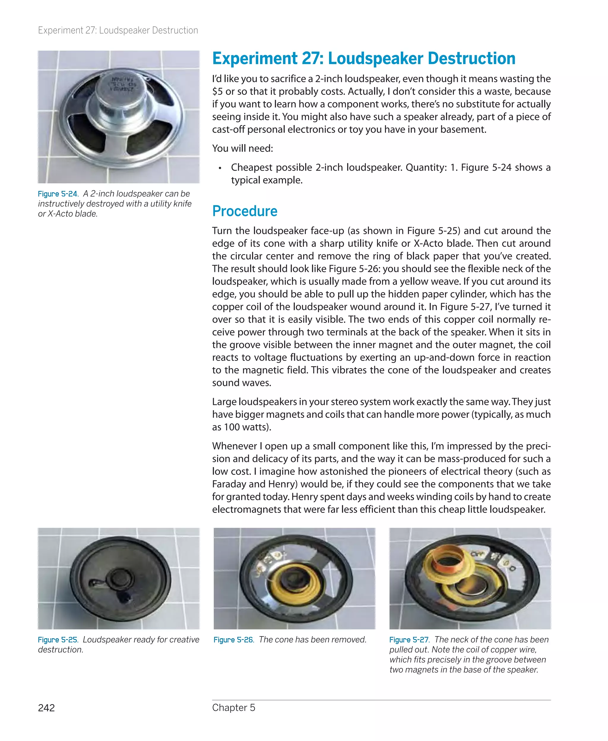
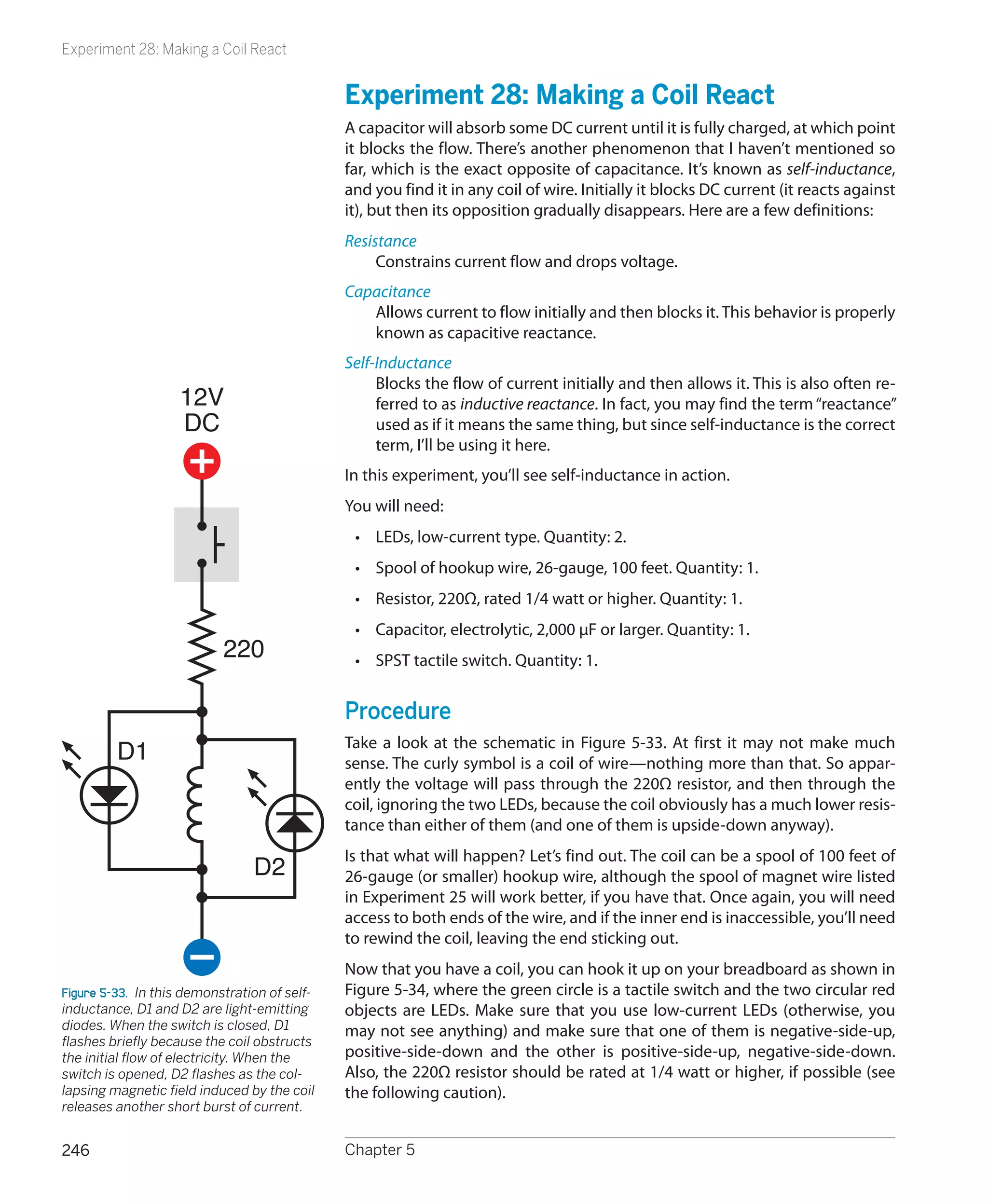
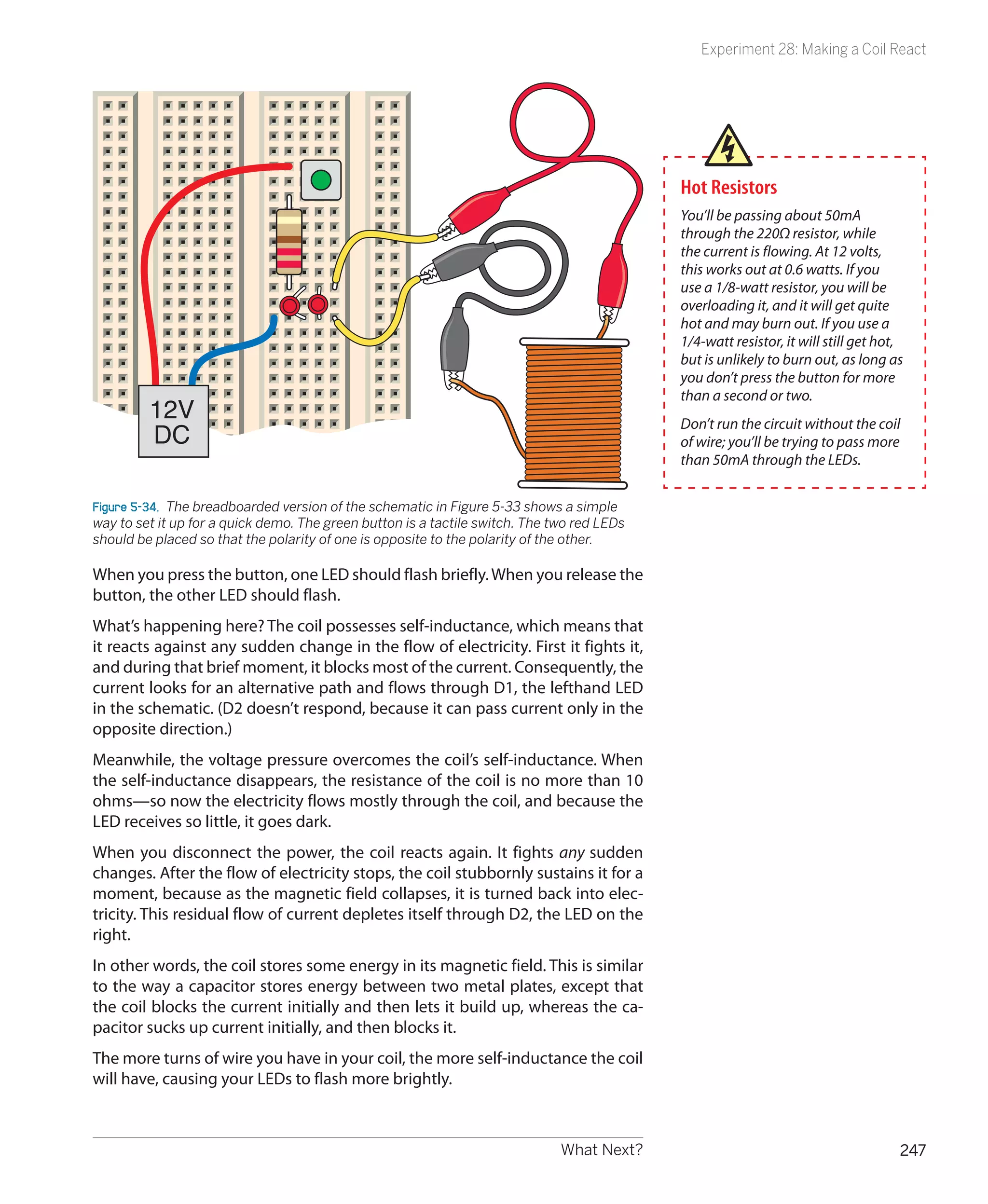
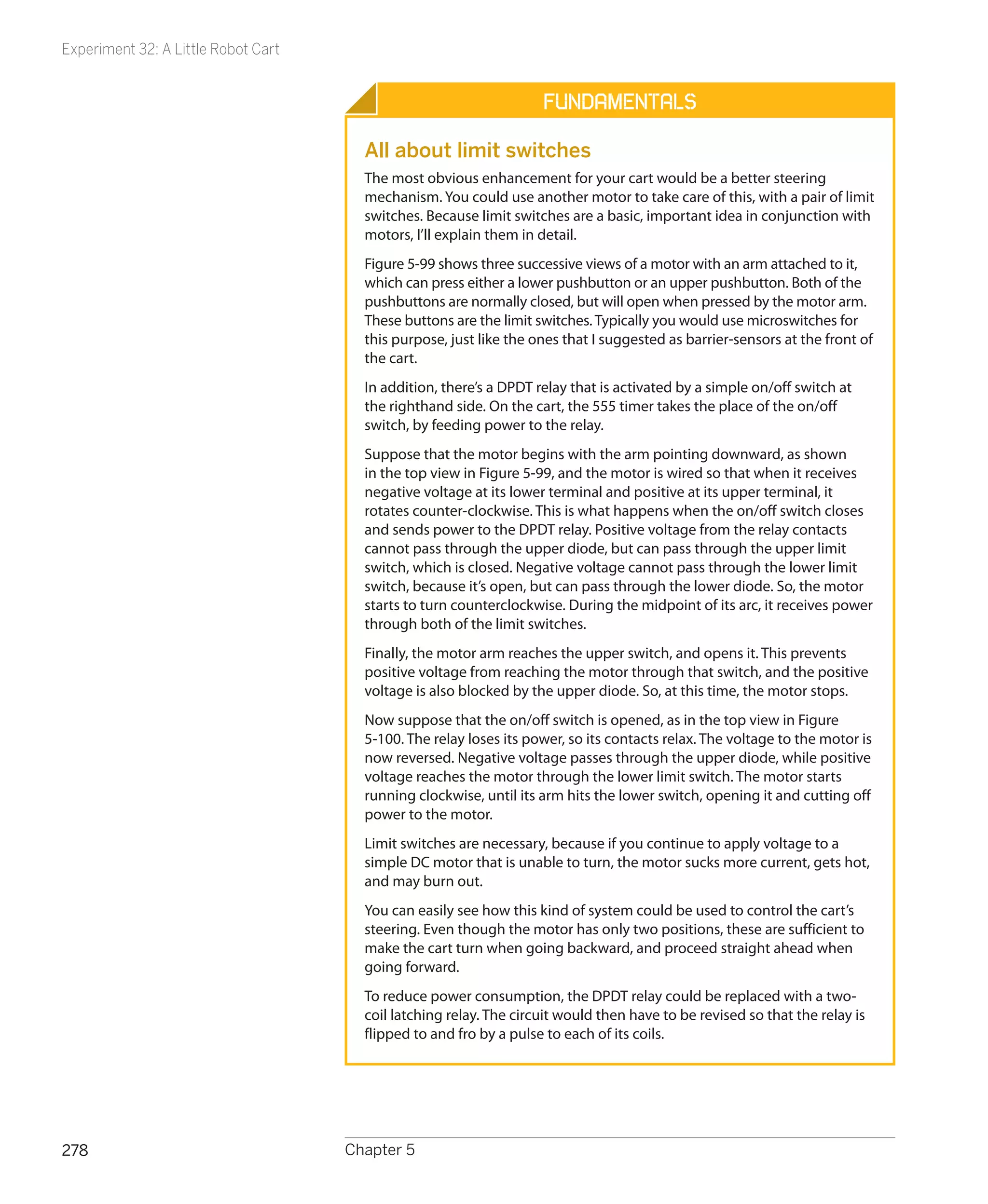
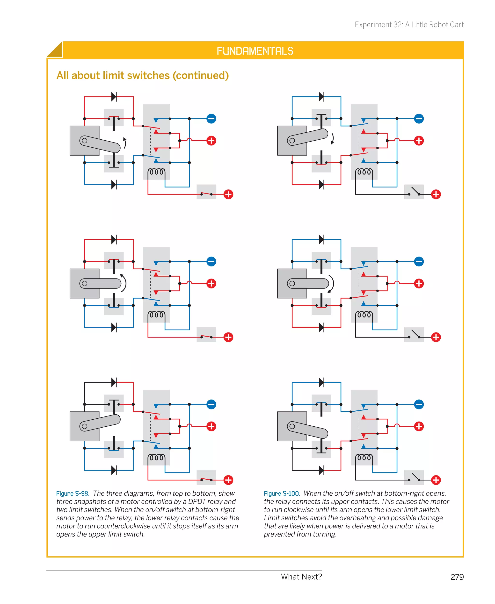
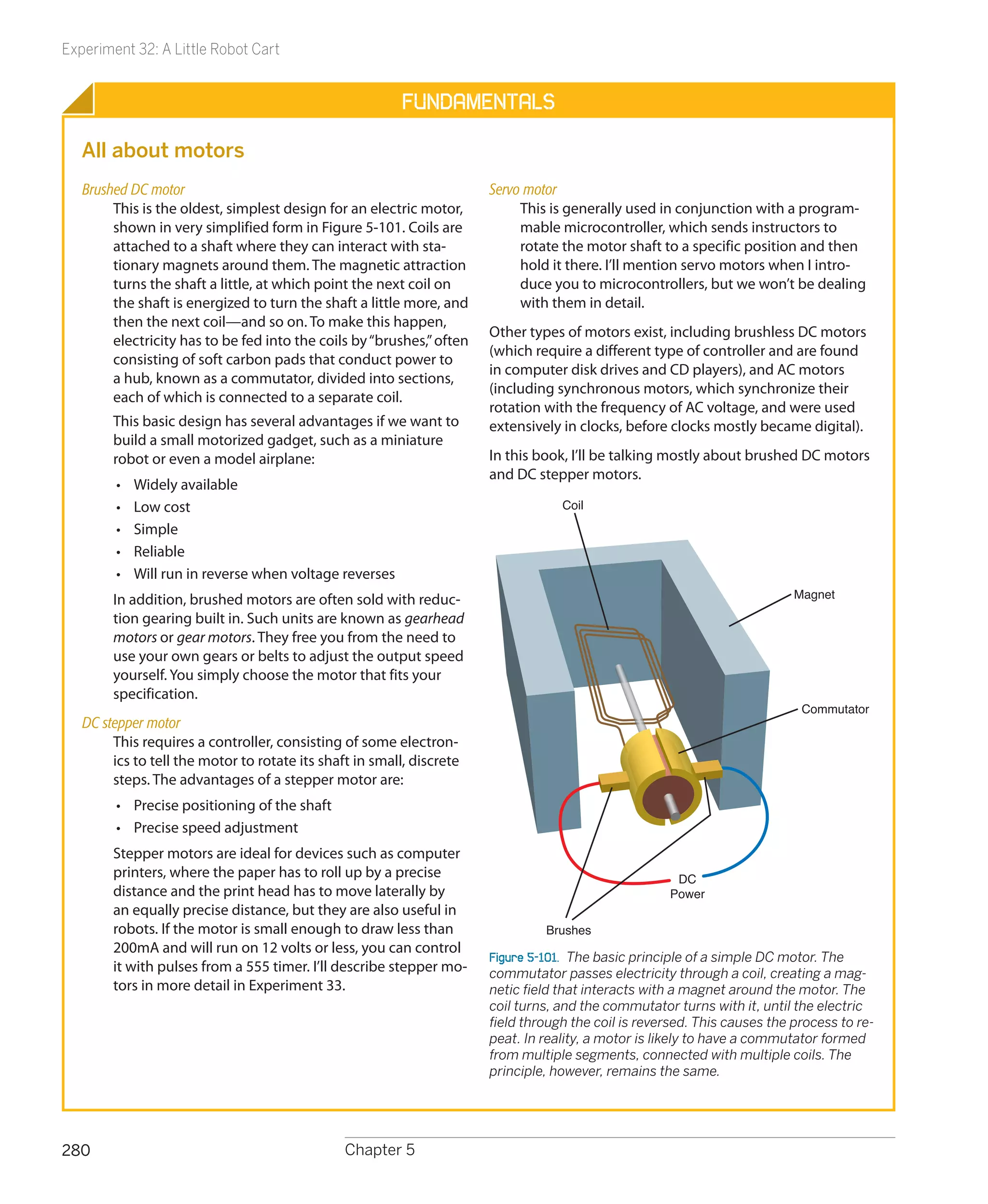
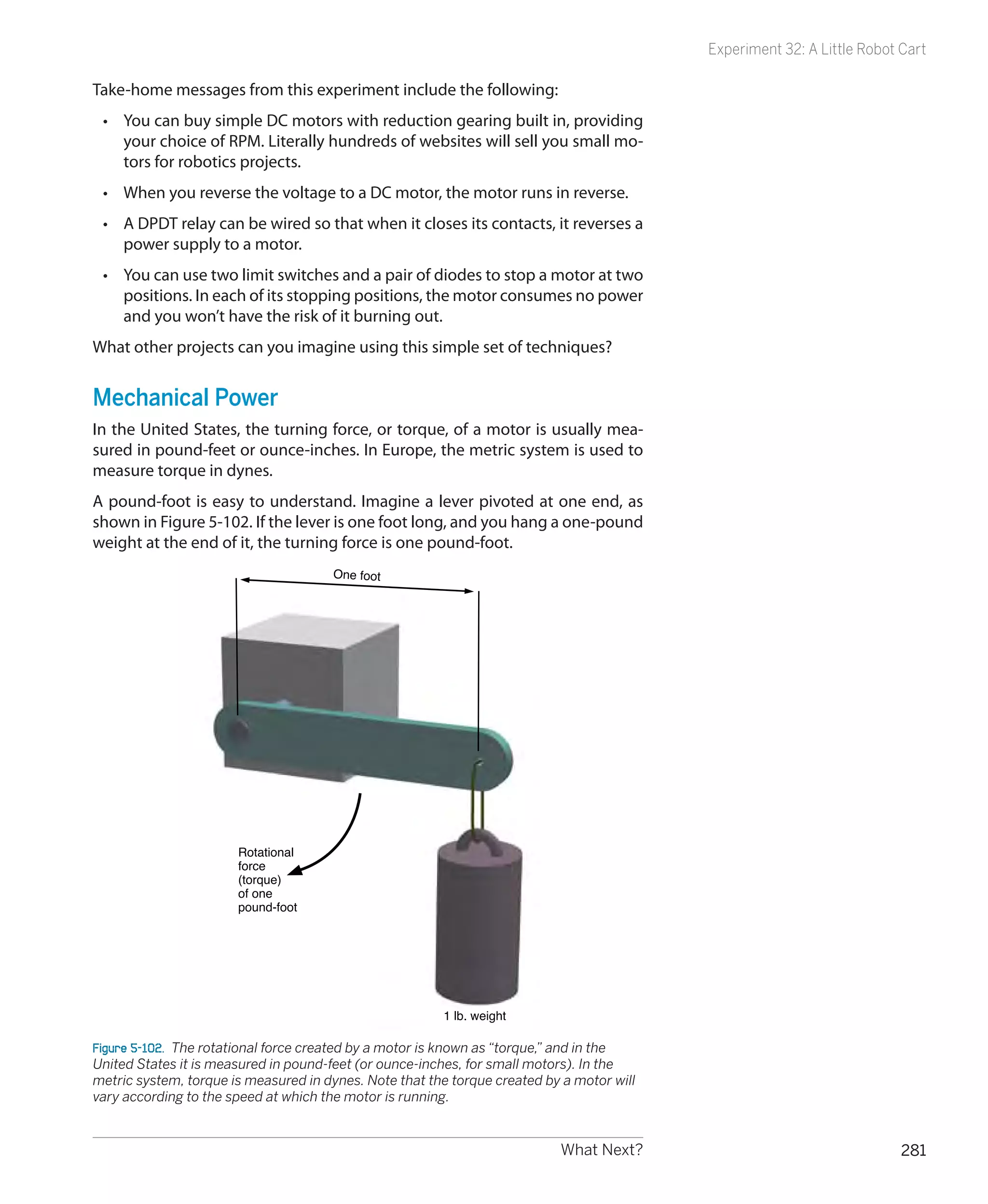
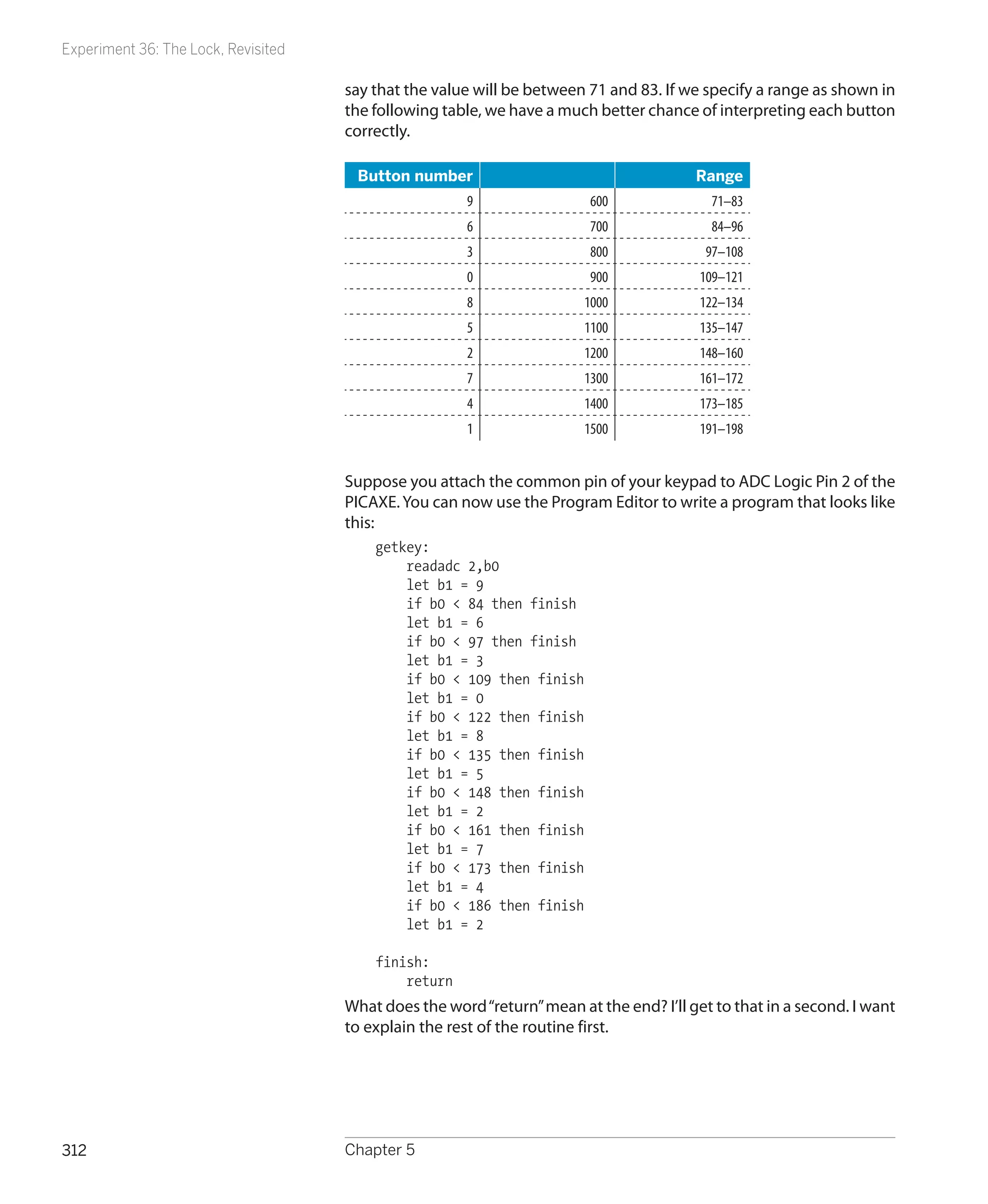
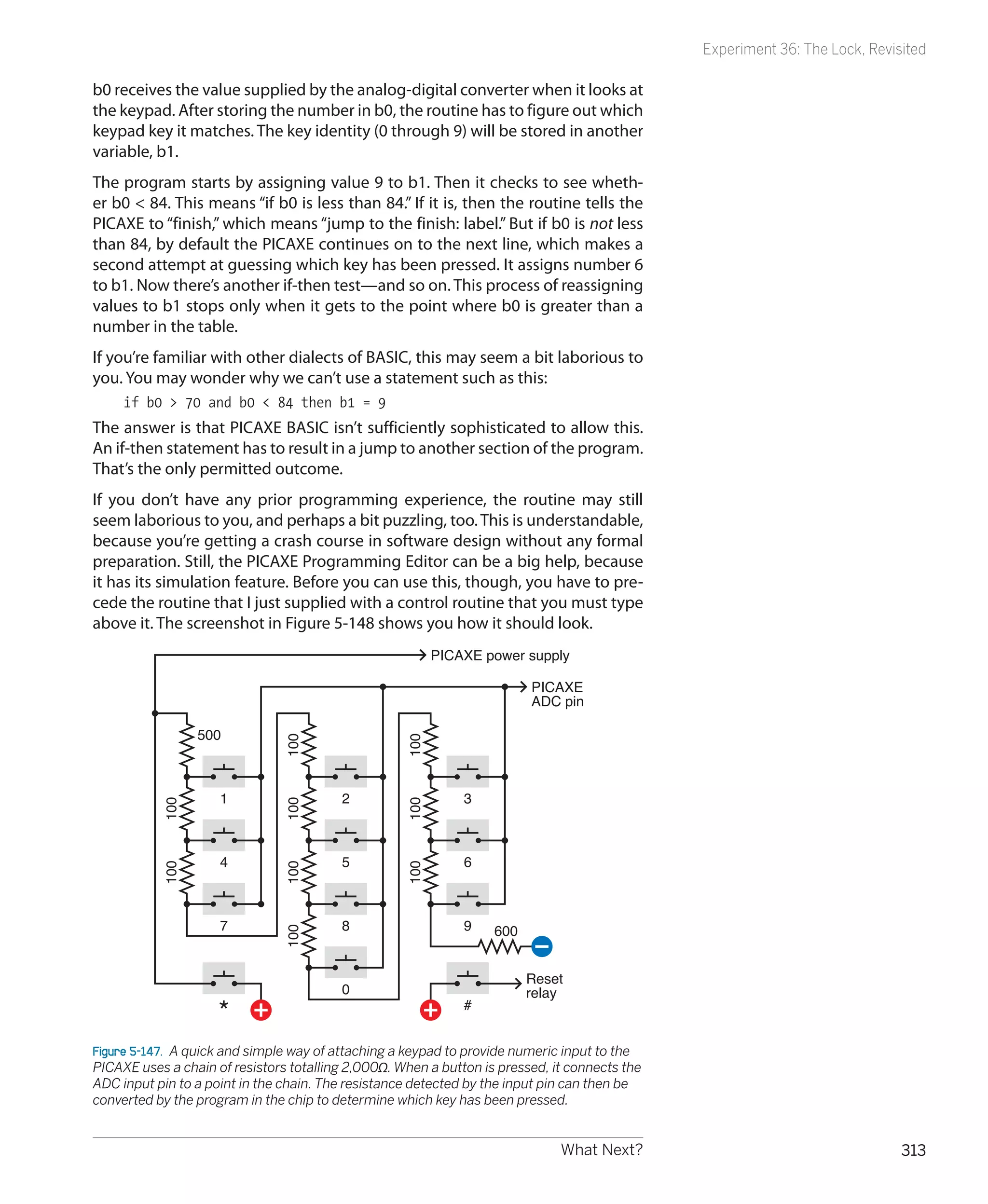
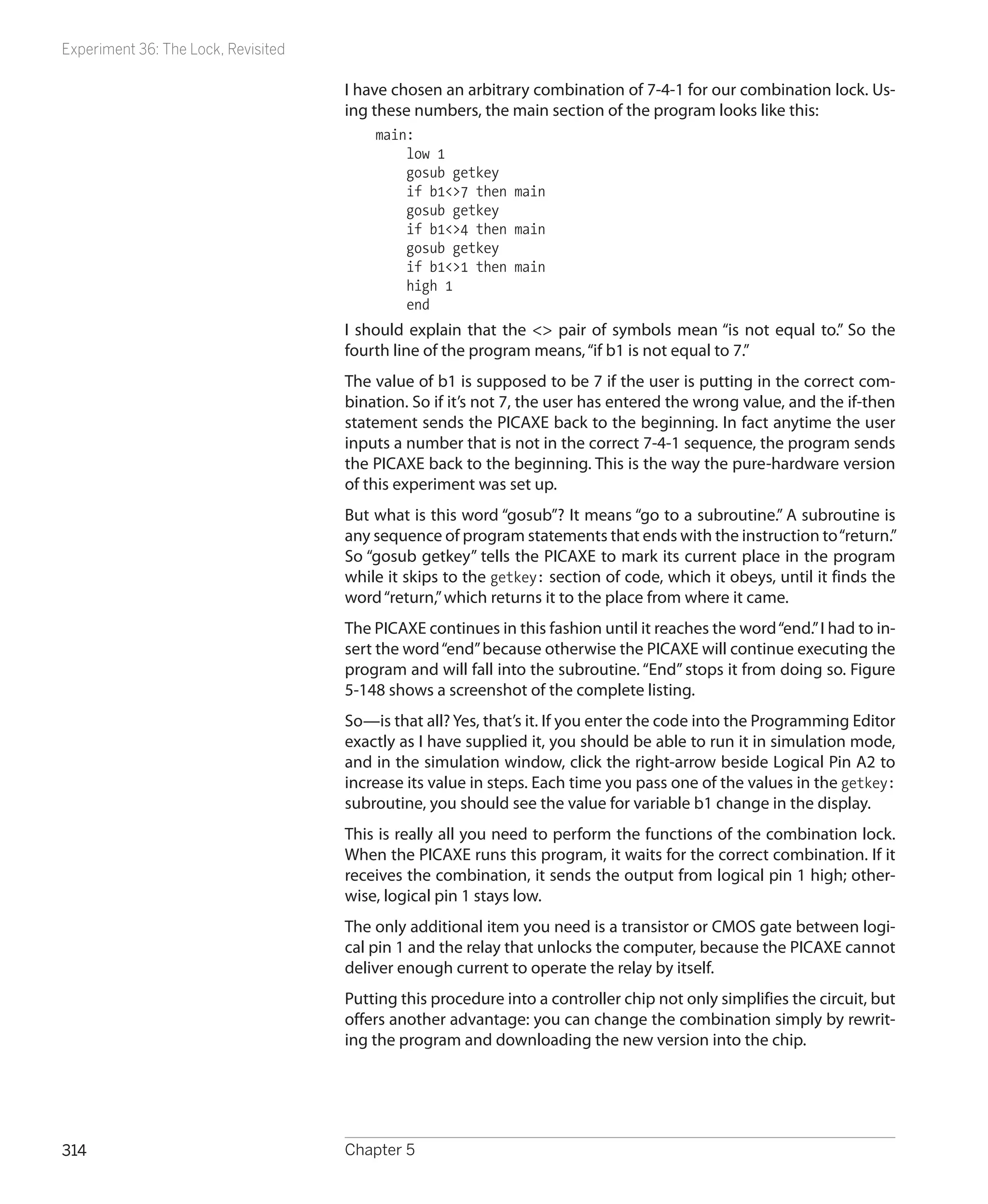
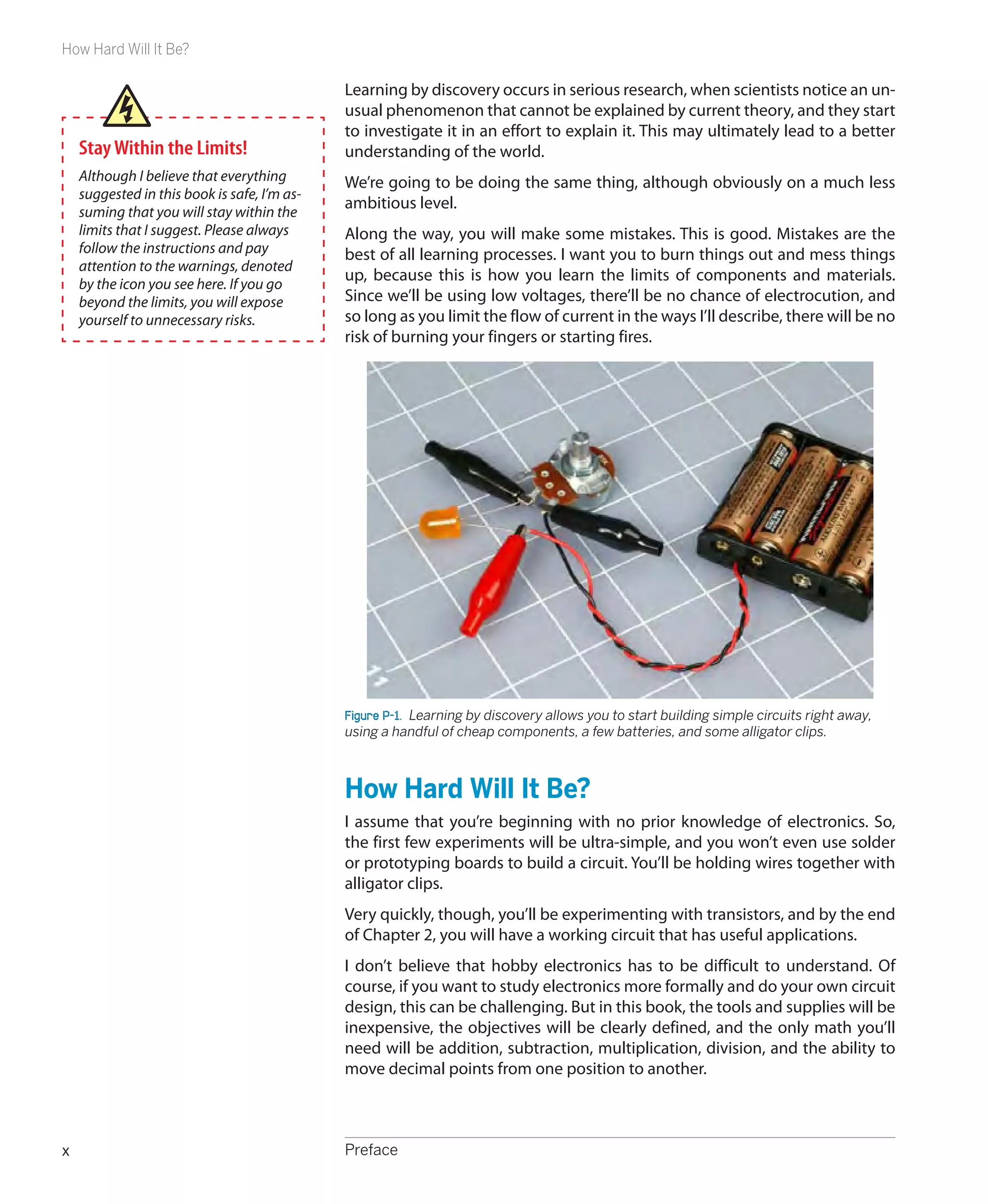
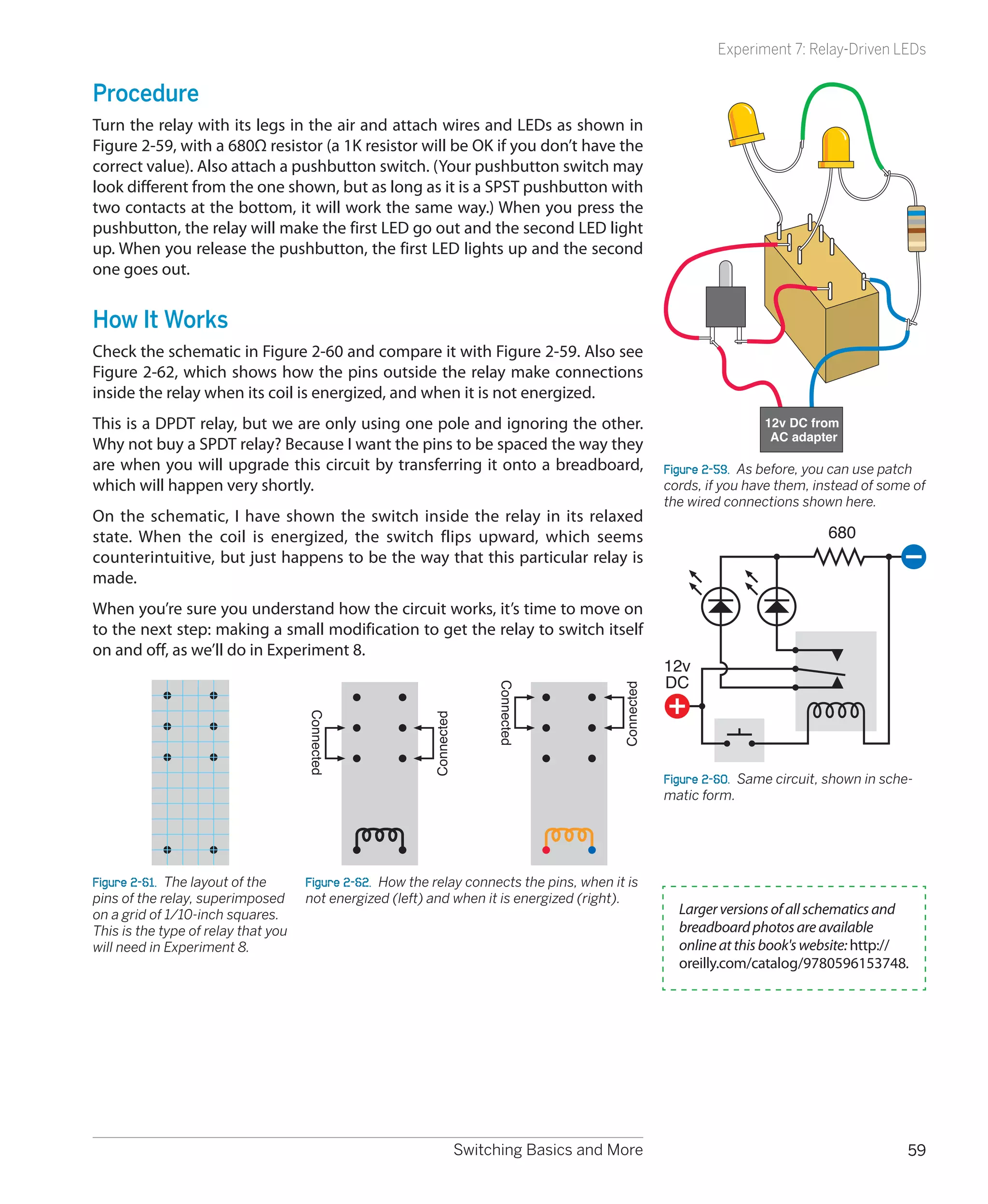
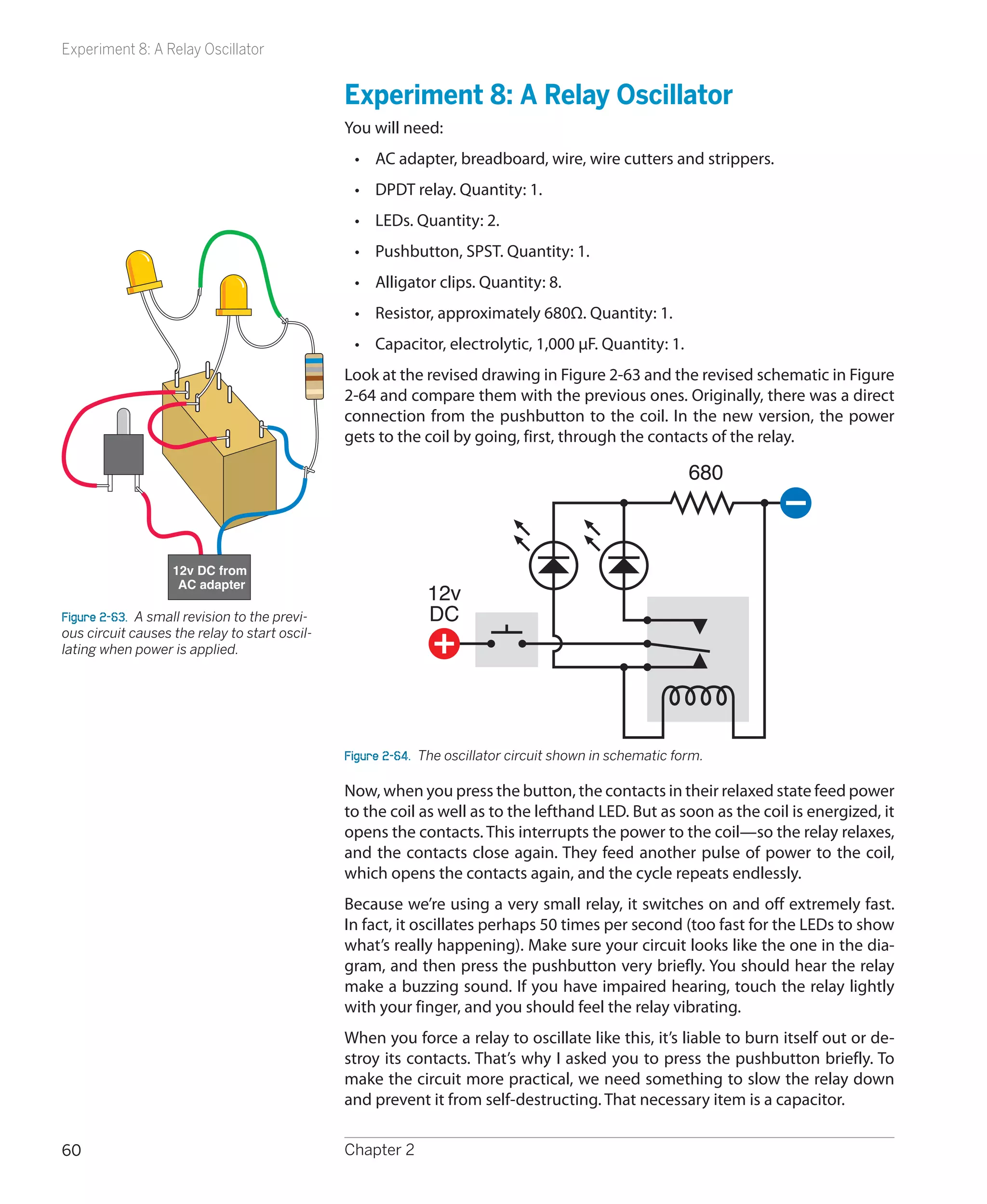
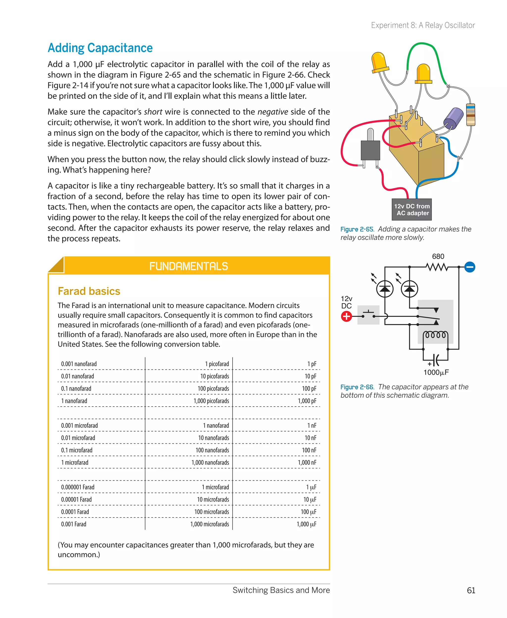
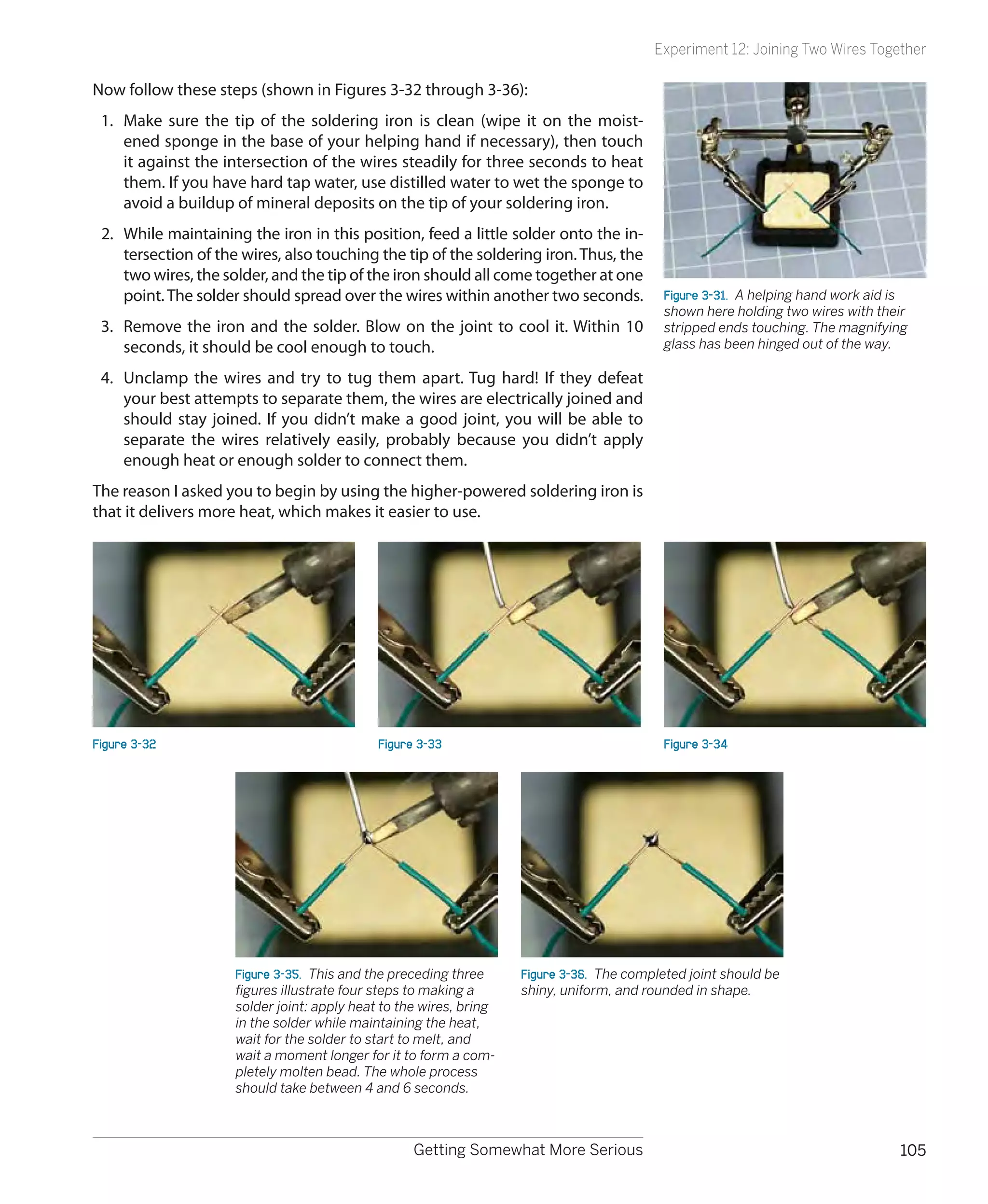
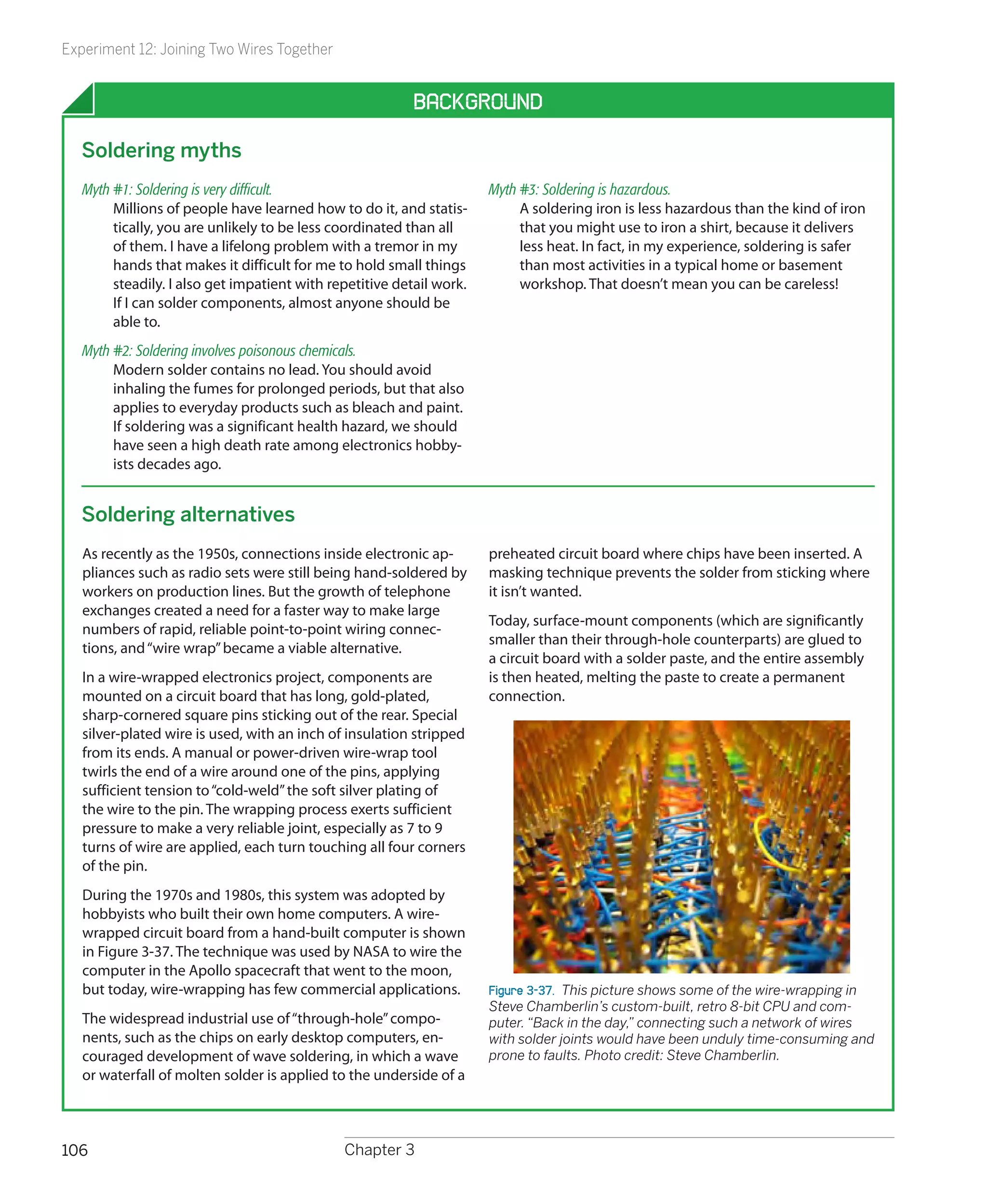
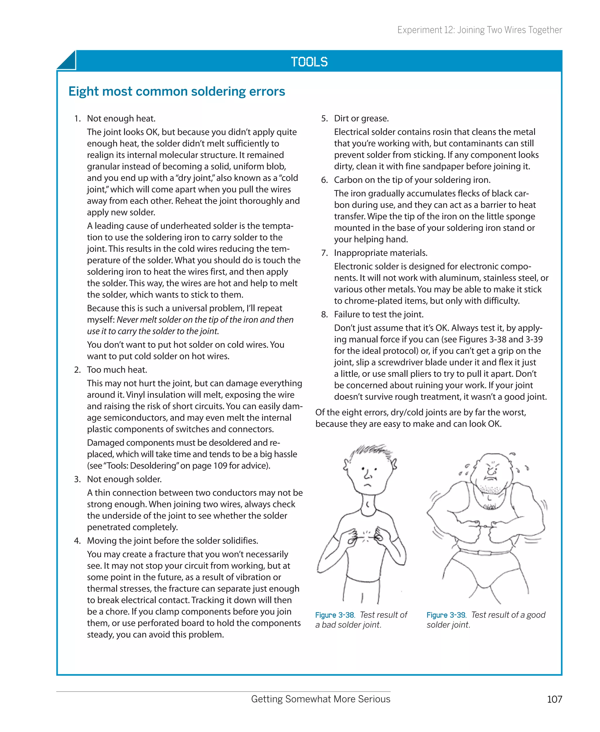
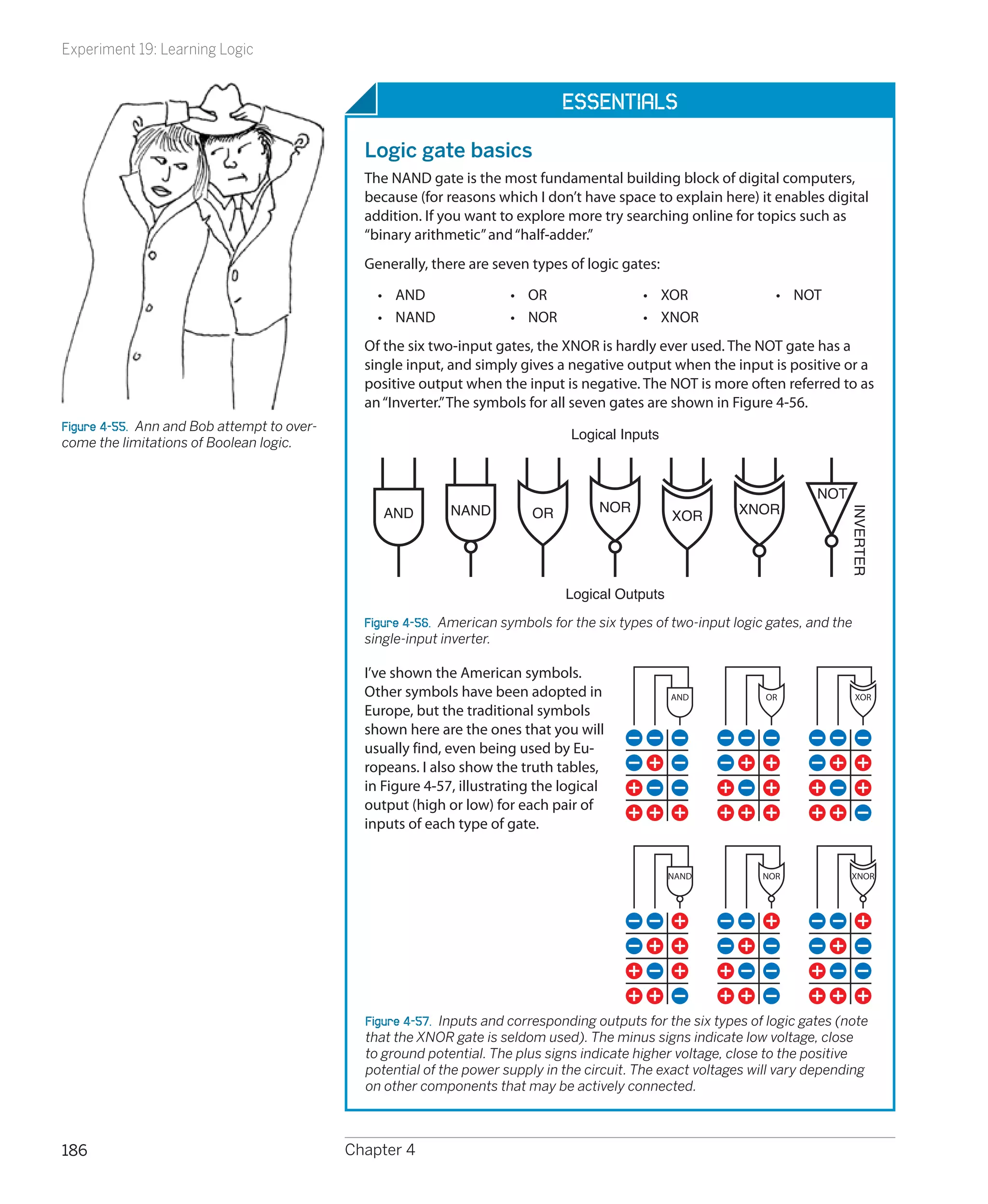
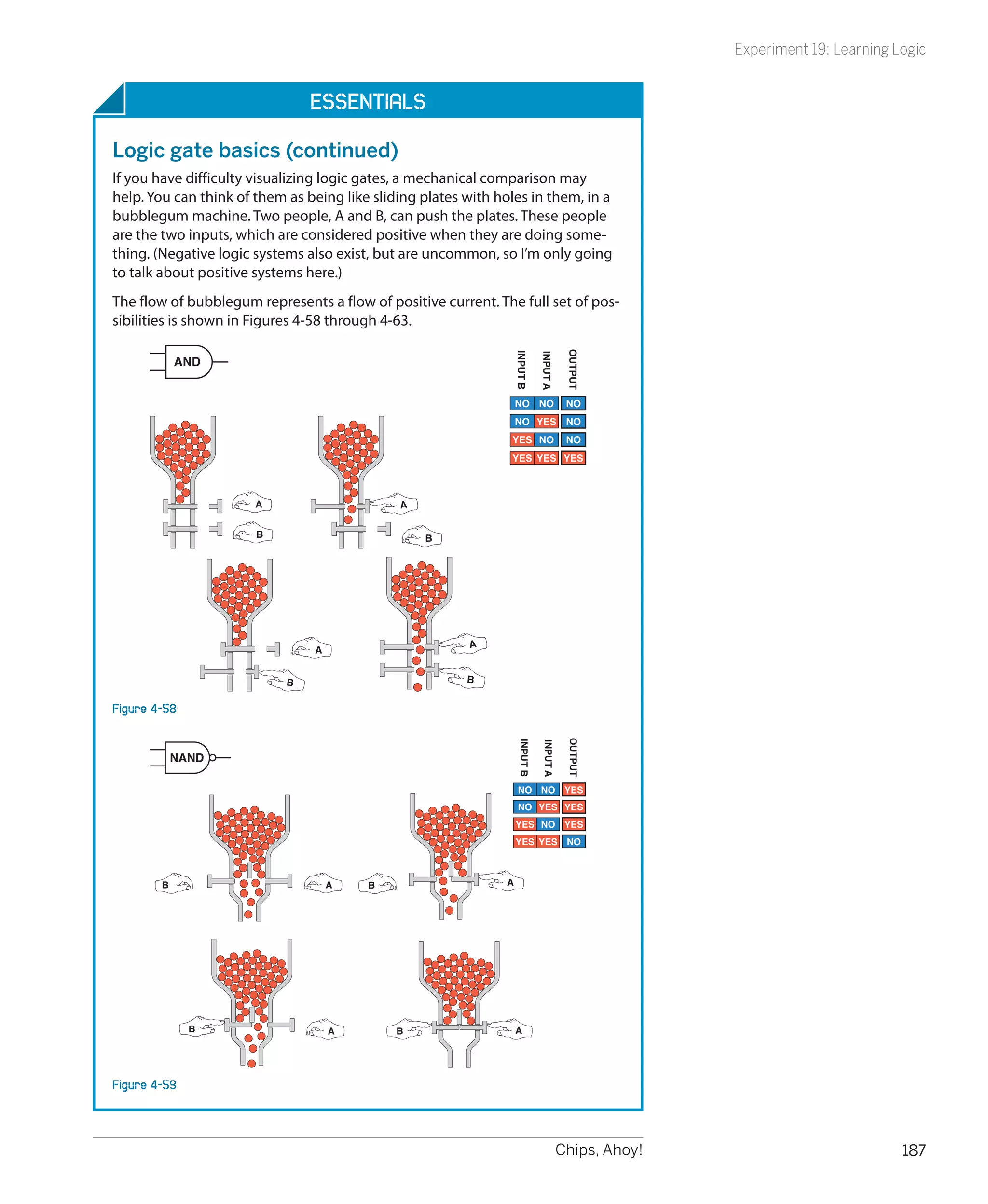
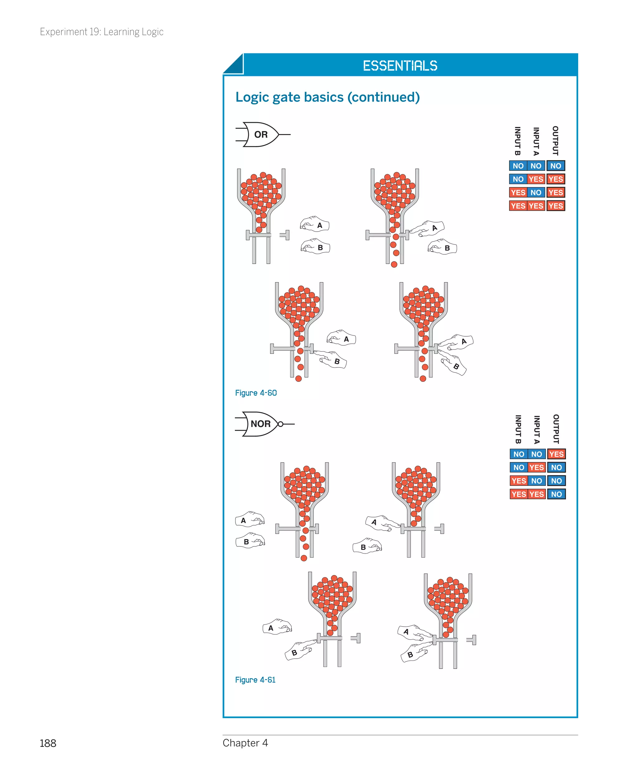
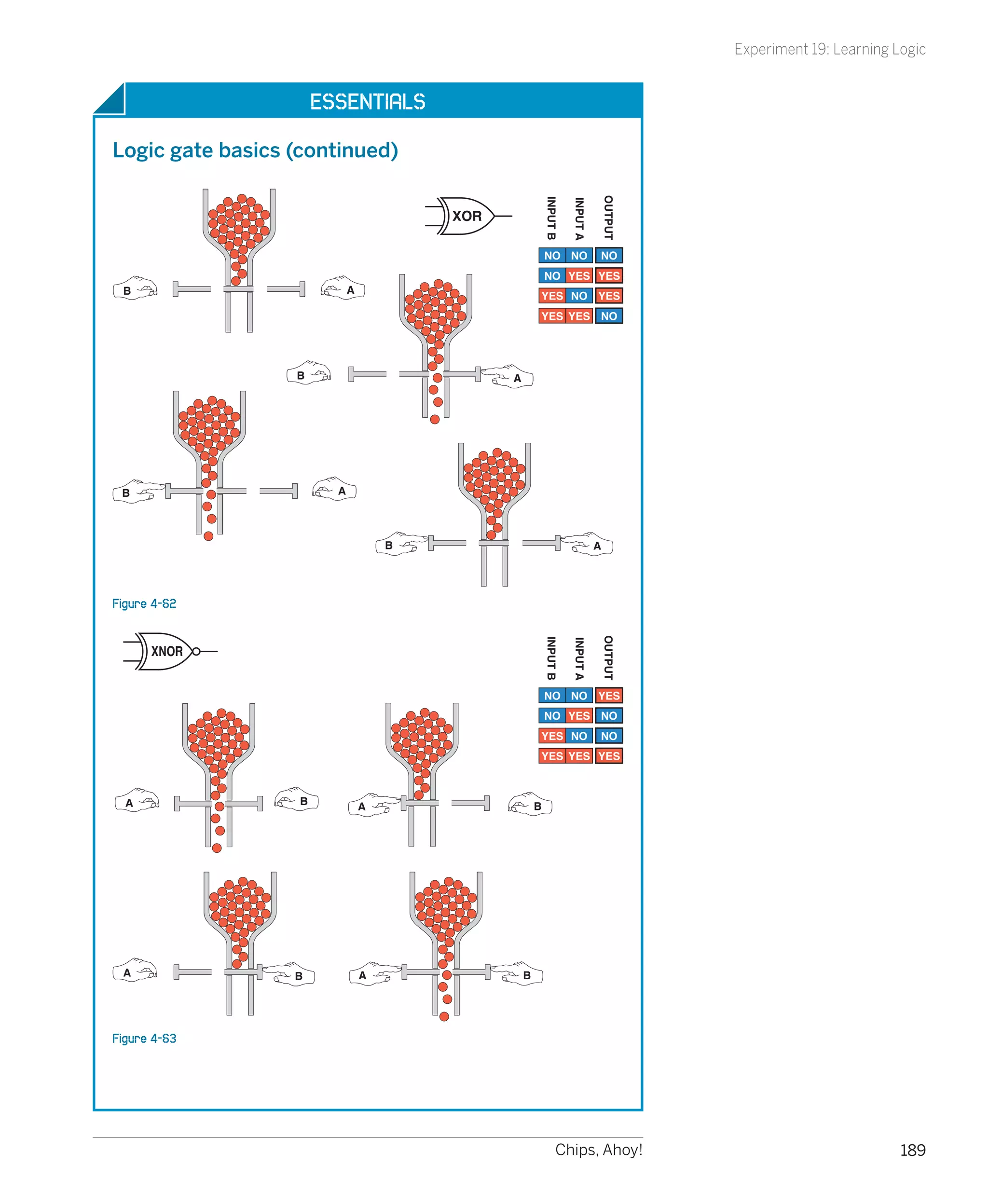
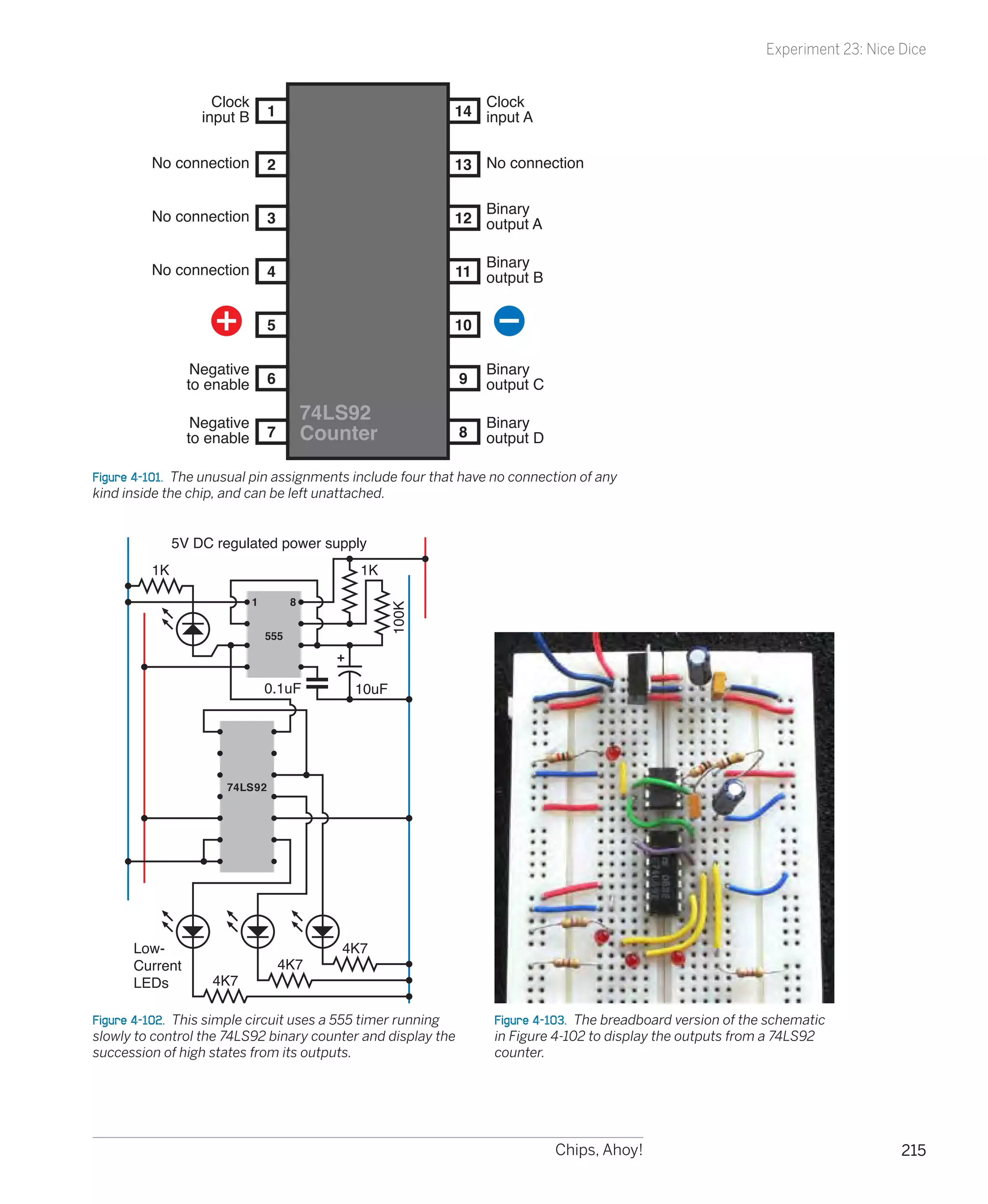
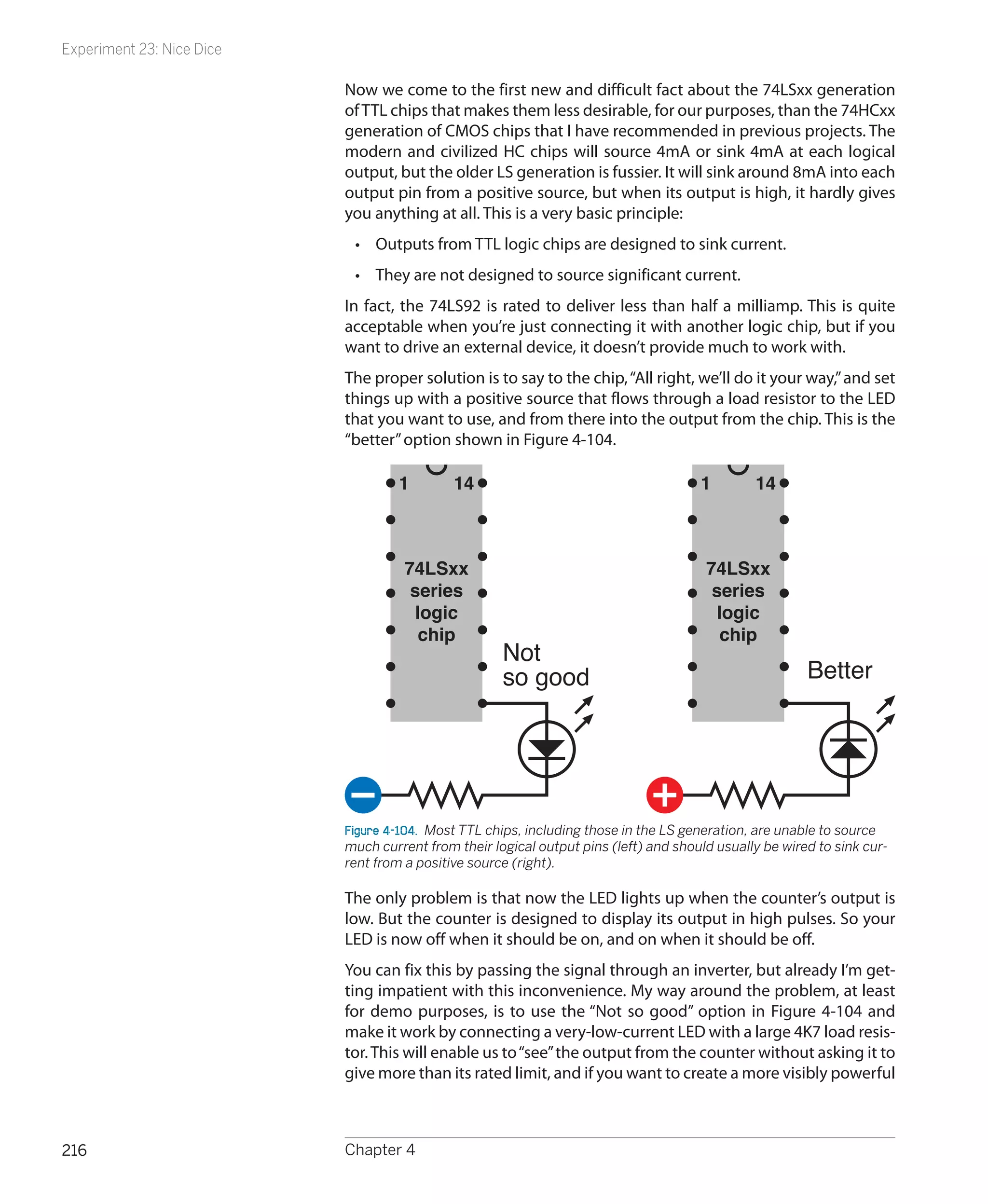
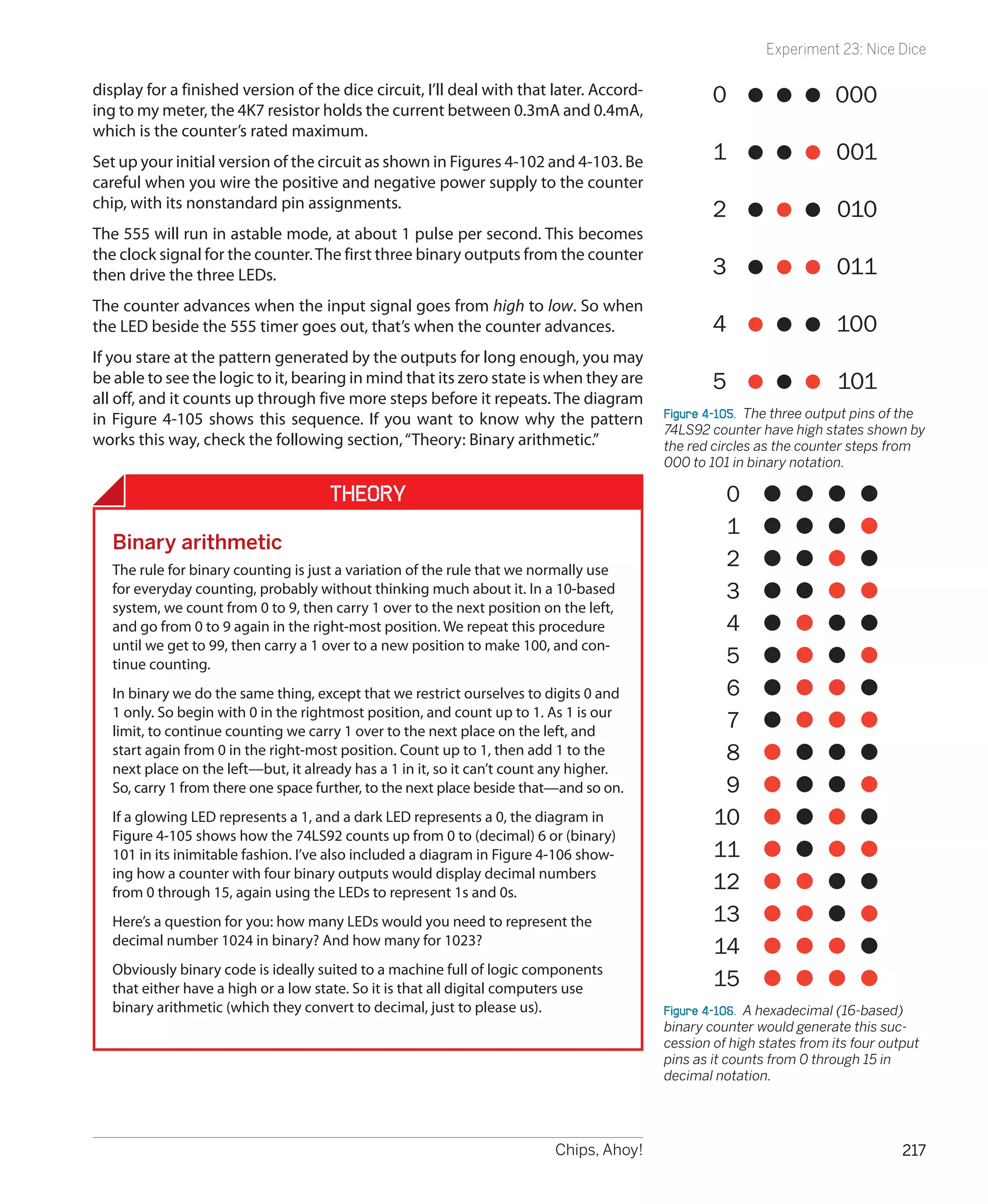
This document is the preface to the book "Make: Electronics" by Charles Platt. It is an introduction to electronics book that contains 36 experiments of increasing complexity using basic electronic components. The preface explains that the goal of the book is to have fun experiencing electricity and electronics through hands-on experiments, to understand some basics of how devices work, and to potentially pursue electronics as a hobby. It encourages the reader to approach the experiments with a sense of play and discovery rather than following instructions exactly.

![Make: Electronics
by Charles Platt
Copyright © Helpful Corporation. All rights reserved.
Printed in Canada.
Published by O’Reilly Media, Inc., 1005 Gravenstein Highway North, Sebastopol, CA 95472.
O’Reilly Media books may be purchased for educational, business, or sales promotional use. Online editions are also avail-
able for most titles (my.safaribooksonline.com). For more information, contact our corporate/institutional sales department:
800-998-9938 or corporate@oreilly.com.
Editors: Dale Dougherty and Brian Jepson
Development Editor: Gareth Branwyn
Production Editor: Rachel Monaghan
Technical Editor: Andrew “Bunnie” Huang
Copyeditor: Nancy Kotary
Proofreader: Nancy Reinhardt
Indexer: Julie Hawks
Cover Designer: Mark Paglietti
Interior Designer: Ron Bilodeau
Illustrator/Photographer: Charles Platt
Cover Photographer: Marc de Vinck
Print History:
December 2009: First Edition.
The O’Reilly logo is a registered trademark of O’Reilly Media, Inc. Many of the designations used by manufacturers and
sellers to distinguish their products are claimed as trademarks. Where those designations appear in this book, and O’Reilly
Media, Inc., was aware of a trademark claim, the designations have been printed in caps or initial caps.
While every precaution has been taken in the preparation of this book, the publisher and author assume no responsibility
for errors or omissions, or for damages resulting from the use of the information contained herein.
ISBN: 978-0-596-15374-8
[TI]](https://image.slidesharecdn.com/make-electronics-120728163130-phpapp02/75/Make-electronics-5-2048.jpg)


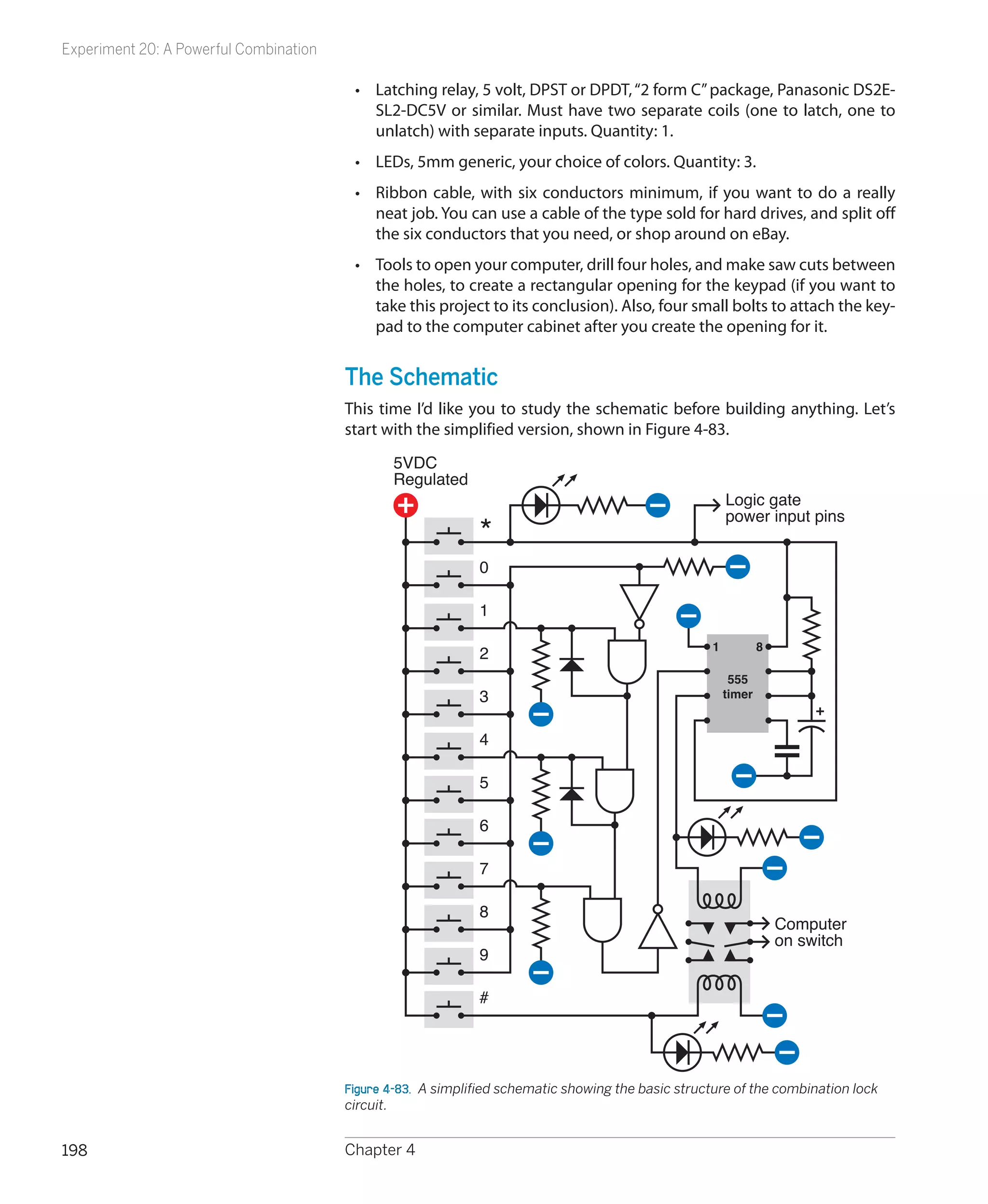

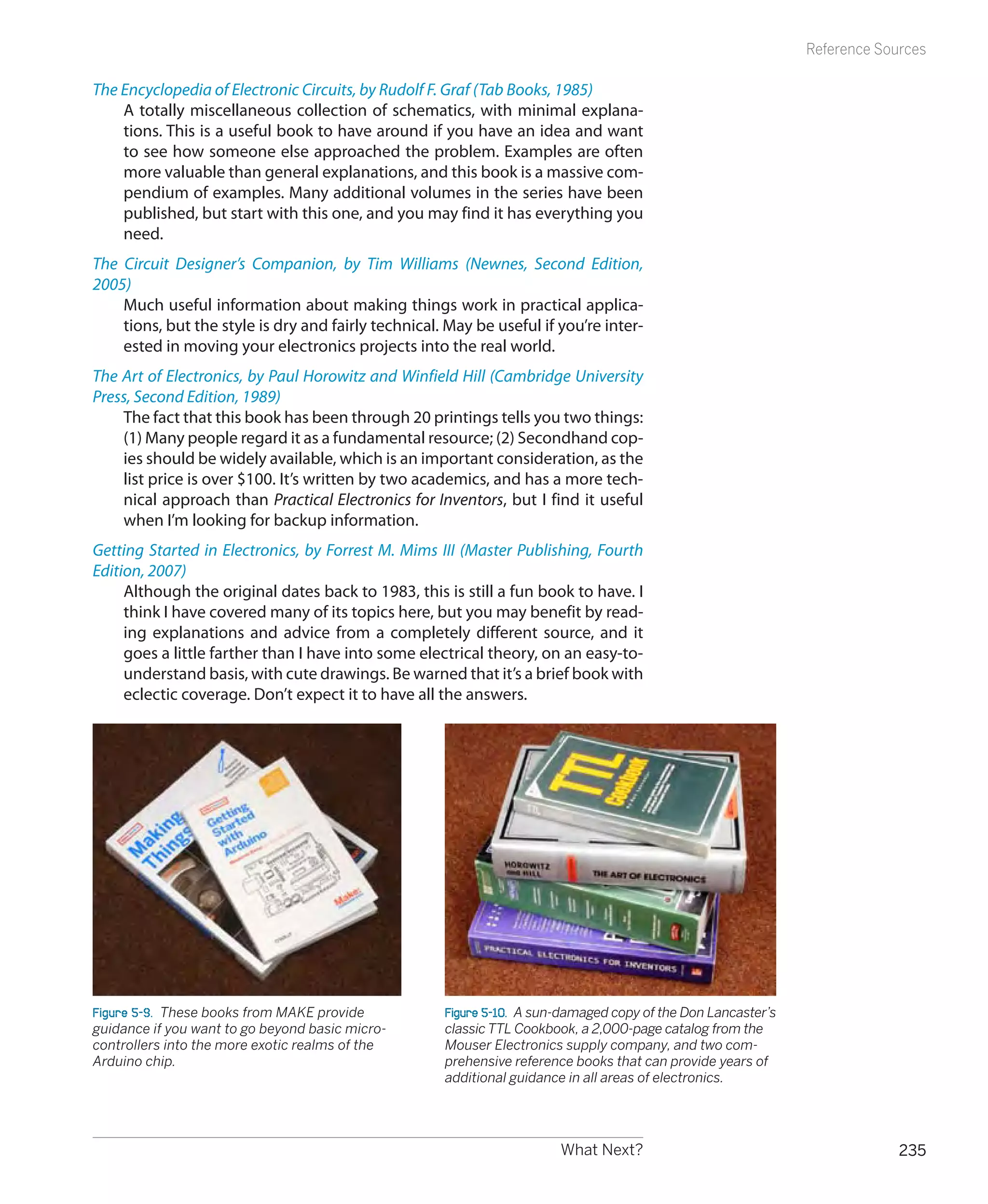
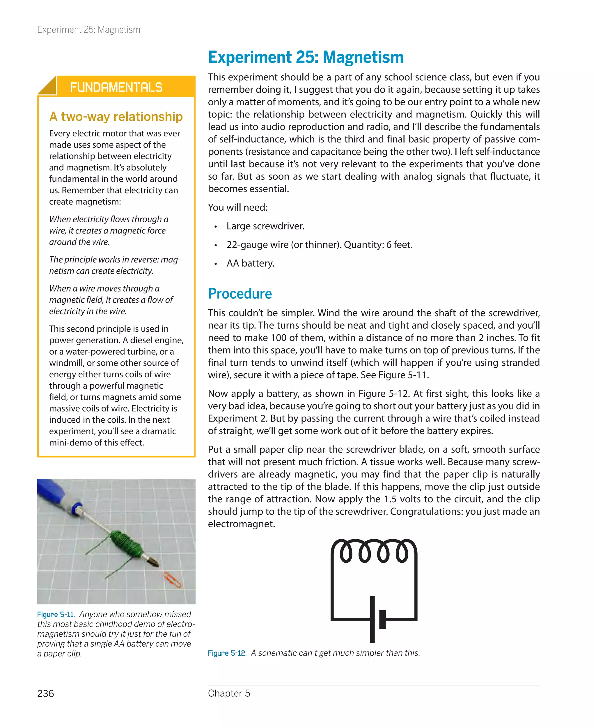
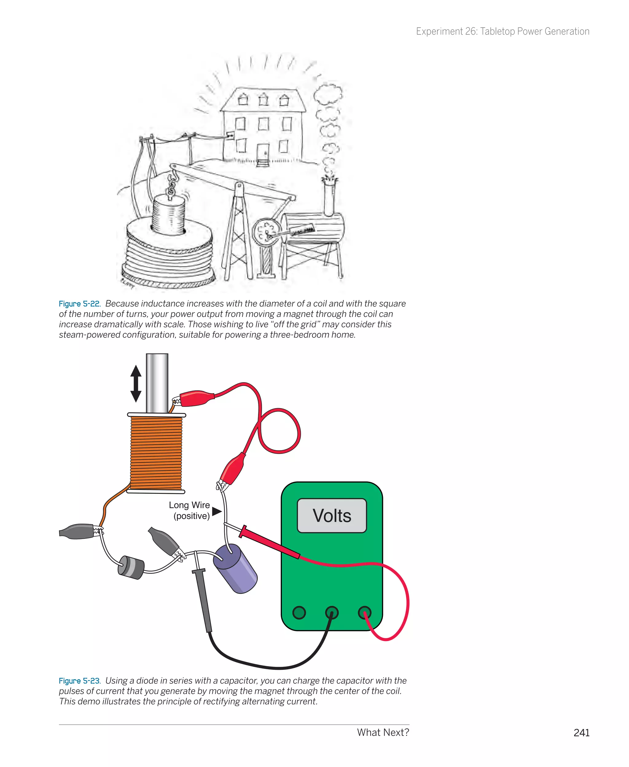
![Experiment 25: Magnetism
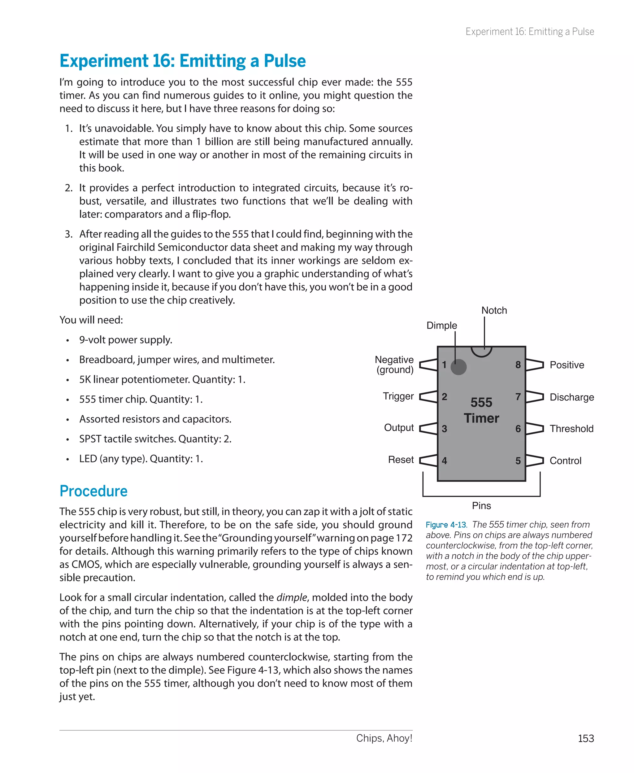
Theory
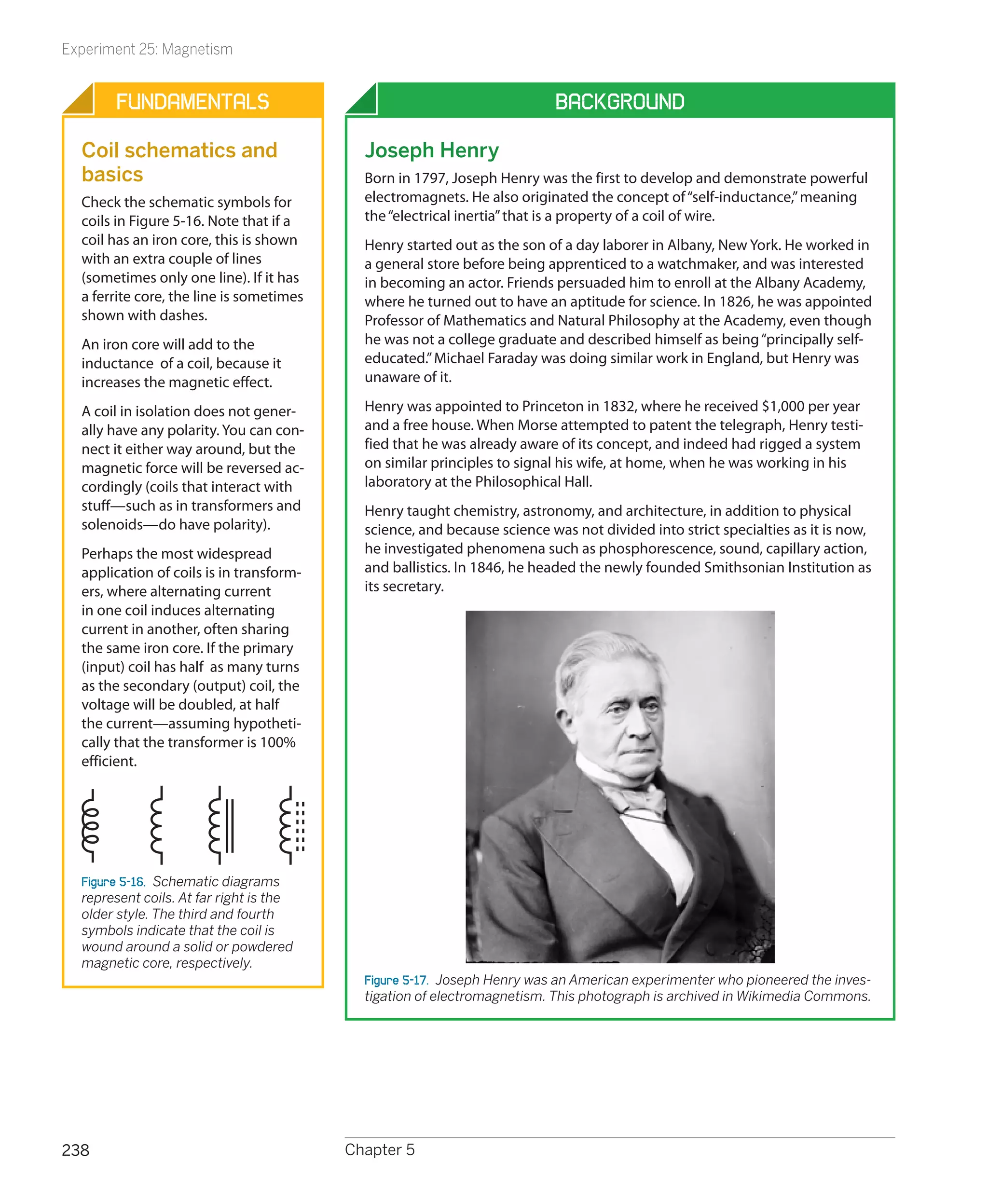
Inductance
When electricity flows through a wire, it creates a magnetic Here’s an approximated formula showing the relationship
field around the wire. Because the electricity “induces” this between the diameter of the coil, the width of the coil from
effect, it is known as inductance. The effect is illustrated in end to end, the number of turns, and its inductance. The
Figure 5-13. letter L is the symbol for inductance, even though the unit
is the Henry, named after an American electrical pioneer
named Joseph Henry:
L (in microHenrys) =
[(D × D) × (N x N)] / [(18 × D) + (40 × W)]
(Approximately)
In this formula, D is the diameter of the coil, N is the number
of turns, and W is the width of the coil from end to end. See
Figure 5-15. Here are three simple conclusions from this
formula:
• Inductance increases with the diameter of the coil.
Figure 5-13. When the flow of electricity is from left to right • Inductance increases with the square of the number of
along this conductor, it induces a magnetic force shown by the turns. (In other words, three times as many turns create
green arrows. nine times the inductance.)
• If the number of turns remains the same, inductance is
The field around a straight wire is very weak, but if we bend lower if you wind the coil so that it’s slender and long,
the wire into a circle, the magnetic force starts to accumu- but is higher if you wind it so that it’s fat and short.
late, pointing through the center of the circle, as shown in
Figure 5-14. If we add more circles, to form a coil, the force N=Number
accumulates even more. And if we put a magnetic object of turns of
(such as a screwdriver) in the center of the coil, the effective- wire
ness increases further.
D=Diameter
of coil
W
=
of Wi
co dth
il
Figure 5-15. The inductance of a coil increases with its diameter
Figure 5-14. When the conductor is bent to form a circle, the cu-
and with the square of its number of turns. If all other param-
mulative magnetic force acts through the center of the circle,
eters remain the same, reducing the width (the distance from
as shown by the large arrow.
end to end) by packing the turns more tightly will increase the
inductance.
What Next? 237](https://image.slidesharecdn.com/make-electronics-120728163130-phpapp02/75/Make-electronics-252-2048.jpg)