Downloaded 427 times

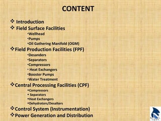
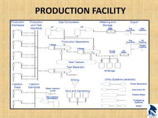
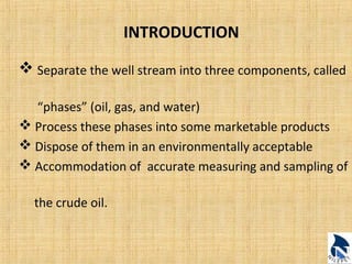
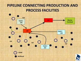
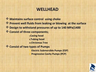
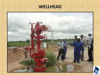
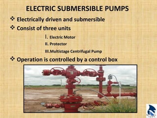

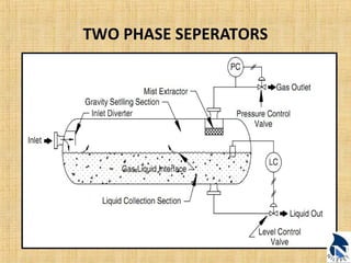
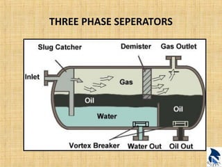
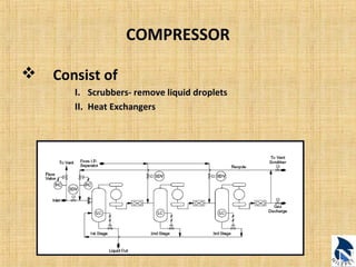

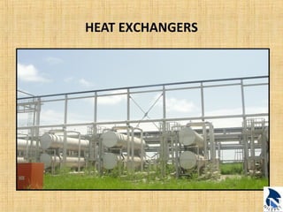

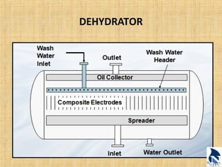
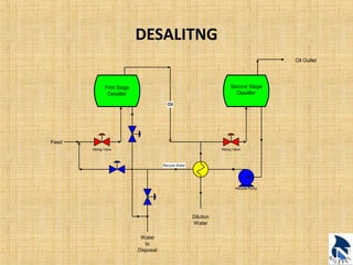
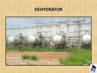
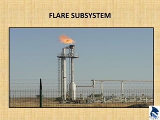
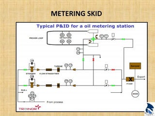
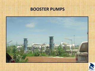
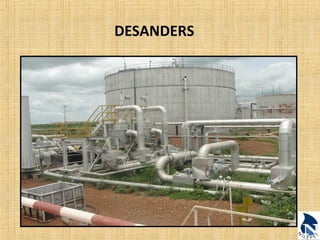


This document provides an overview of upstream oil and gas production facilities, including field surface facilities, field production facilities, and central processing facilities. It describes the key components and functions of these facilities. These include wellheads, pumps, manifolds, separators, compressors, heat exchangers, dehydrators, meters, tanks, flares, and control systems. Power is generated onsite and distributed to run the various equipment used in processing raw production into marketable products and disposing of byproducts.


