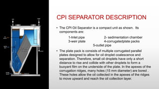
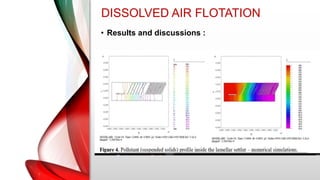
CPI SEPARATOR
(CORRUGATED PLATE INTERCEPTOR)
&
DAF UNIT
(DIFFUSED AIR FLOTATION)
Ahmed Samir Abdelaal Ebrahim
Abdul Hamid Saeed Ibrahim Musa
Mohamed Khaled Ahmed Attia
CPI SEPARATOR DESCRIPTION
• The CPI Oil Separator is a compact unit as shown. Its
components are:
1-Inlet pipe 2- sedimentation chamber
3-weir plate 4-corrugatedplate packs
5-outlet pipe
• The plate pack is consists of multiple corrugated parallel
plates designed to allow for oil droplet coalescence and
separation. Therefore, small oil droplets have only a short
distance to rise and collide with other droplets to form a
buoyant film on the underside of the plate. In the apexes of the
corrugation ridges, many holes (15 mm diameter) are bored .
These holes allow the oil collected in the apexes of the ridges
to move upward and reach the oil collection layer.
PROCESS DESCRIPTION
• The produced water containing oil and partly dissolved
hydrocarbon gases enters the separator above the free liquid
surface. The enables part of the gas to immediately free itself
from the liquid and flow towards the gas outlet. A foam screen
is provided in the inlet section of the separator to eliminate the
possibility of water and oil mist being carried towards the gas
outlet.
• Likewise, sand and other solid particles, which are frequently
present in produced water streams, will settle on the bottom of
the primary compartment where they can be released during
the process by intermittent operation of the desludging valves.
PROCESS DESCRIPTION
• The oily water flows into the pack of inclined plates from the
top and passes down through the plate pack. The plate pack is
hydraulically designed in such a way that laminar flow
conditions exist in each ‘channel’ (i.e. the distance between
the subsequent plates). In this laminar flow the minute oil
droplets rise by virtue of the fact that their density is less than
that of the water and attach themselves to the underside of the
upper plate of the channel.
• The build-up oily layer that is constantly being formed at the
underside of each plate creeps slowly upwards along the
plates. At the top of each plate the oil film is concentrated
(coalesced) by the special fingers and leaves the plate at the
fingertips as a thick stream or a rising chain of large bubbles
PROCESS DESCRIPTION
• Also any micron size gas bubbles, still contained in the water
after initial gas release in the primary chamber, will rise. These
gas bubbles in general are oleophylic so that they will easily
adhere to the minute oil droplets.
• This ‘natural flotation’ effect gives the oil droplets an
increased rising velocity and thus accelerates the separation
process.
• The layer of separated oil flows at a constant rate over a fixed
weir into the recovered oil sump from where it can be released
intermittently during the process via a level switch controlled
valve. The treated water leaves the separator vessel via the
control valve an can be further treated if required by floatation
or filtration.
PARAMETERS AND EQUATIONS
the effectiveness of this technique is subjected to various factors
such as density difference, the viscosity of the oil, factors of the
medium, temperature, turbulence, and also the nature of impurity
etc
• the differences in densities of the two liquids cause droplets to
rise or fall by their buoyancy as shown
The viscous force acting on anoil droplet or particle is directly
proportional to the following parameters
 the radius of the droplet. ●coefficient of viscosity.
 the velocity of the droplet
Conclusion from mathematical modeling
• Decreasing Re leads to increasing separation efficiency
• Increasing the droplet diameter increases the separation efficiency
and decreases the catch length
• Decreasing the catch length will lead to decreasing the residence
time and
• When the plate spacing increases that leads to decreasing the
separation efficiency and increasing both of catch length and
residence time.
• It is recommended that the water and oil mixture's entry speed
should be 1.5 cm / s and the distance between the oil separator
layers be 7 mm when the length of the plats is 590mm to improve
the separation efficiency and to remove 30-micron droplets within
approximately 36 seconds. This Optimizes operation conditions to
reduce operation costs
PARAMETERS AND EQUATIONS
• The oil-globule rise rate () can calculated by :
𝑣𝑡 =
𝑔
18 ∗ 𝜇
(𝜌𝑤 − 𝜌𝑜)𝐷2
or 𝑣𝑡 = 0.0123(
𝑠𝑤−𝑠𝑜
𝜇
) where D=0.015 cm
As
s : specific gravity
𝜇 : absolute viscosity of waste-water at design temperature
CPI SEPARATOR
• Advantages Of Designed CPI Separators in Oily
Water Treatment System :
Low Spare requirement.
Very low maintenance cost since there are no moving parts.
High efficiency and capacity combined with compact volume
Can handle shock loads of flow without affecting effluent
quality significantly.
Selection can be done from large number of type of basins
(RCC, Mild Steel, Stainless Steel) for plate packs in TPI/CPI
separators.
A schematic of CPI separator is depicted below.
no energy consumption except water pumping.
CPI SEPARATOR
Disadvantages Of Designed CPI Separators in
Oily Water Treatment System :
 The effluent oil concentration is higher than that of
other methods.
 Large surface area required.
 Large volume results in dead zones in reduction of
net available surface area.
 Expensive oil/bottom scrapers required that are
maintenance intensive.
 Ineffective with small oil droplets or emulsified oil,
Require long retention time to achieve efficient
separation.
DISSOLVED AIR FLOTATION
• DAF systems are designed to remove total
suspended solids (TSS), biochemical oxygen
demand (BOD), and oils and greases (O&G) from a
wastewater stream. Contaminants are removed
using a dissolved air-in-water solution produced by
injecting air under pressure into a recycle stream of
clarified DAF effluent. This recycle stream is then
combined and mixed with incoming wastewater in
an internal contact chamber where the dissolved air
comes out of the solution in the form of micron-
sized bubbles that attach to the contaminants. The
bubbles and contaminants rise to the surface and
form a floating bed of material that is removed by a
surface skimmer into an internal hopper for further
handling.
DISSOLVED AIR FLOTATION
• Flotation represents a separation process (physical
and chemical) of pollutant (solid matter and/or fats)
by establishing a contact in different phases: the
floating pollutant, the liquid phase and air.
Nowadays, this is an important separation
technique, frequently used around world, and its
applications varies from selective separation of
minerals to ions and even microorganisms
• Dissolved air flotation (DAF) was also worldwide
used during the last fifty years for the removal of
oils, greases and suspended solids. Nowadays,
DAF systems are frequently applied in wastewater
treatment field, product recovery, and thickening of
biological solids in industries such as textile and
leather, paper and cellulose, food processing etc
DISSOLVED AIR FLOTATION
• Artificial flotation represents a process in which air
is forced introduced into the wastewater. The air
bubbles rising to the surface adhere to the
suspended particles or emulsified fats presented in
the liquid and lead pollutants to the wastewater
surface. The large interface contact surface
produced by the formation of air bubbles in the
water mass requires the necessity of an energy
input proportional to their superficial energy -
"potential energy". This process is based on the
adheration capacity of the dispersed particles, solid
or liquid at the gas/air bubbles, forming
conglomerates that using the ascending force of the
bubble rise to the water surface.
DISSOLVED AIR FLOTATION
• Experimental procedures :
The dissolved air flotation unit consists of two
main equipment: a pressurized capsule and a
lamellar settler. One of the most important
element of DAF is the pressurized capsule in
which the water comes into contact with the
compressed air. Air consumption in the transfer
process is (20 – 100) Ndm3/m2 water, that is (1.5 -
5.0)% of the water volume. Inside the pressurized
capsule which is a cylindrical chamber having at
the ends 2 caps are introduced water and air
under pressure. Under pressure conditions (6 bar)
the air in dissolved into the water mass. The
detention time and the contact surface area are
important in order to increase the amount of
dissolved air;
DISSOLVED AIR FLOTATION
• Experimental procedures :
with benefit to the flotation process (an increase of
the specific flow rate and of the saturation
coefficient). Achieving a very fine dispersion of the
water may increase the contact area.
At the top of the capsule is located the circuit for
water feeding with the help of 4 sprinklers as fine
dispersed droplets and not as jet. At the bottom of
the capsule is positioned the air supply (figure 1).
The researchers found that introducing moving
plastic elements inside the capsule will lead to
obtaining a longer time contact between air
bubbles introduced through the circular pipe and
the water.
DISSOLVED AIR FLOTATION
• Experimental procedures :
The longitudinal settler consists in two
compartments placed in series: a lamellar zone
and a technical room (figure 2). At the usual
lamellar clarifiers the clogging phenomenon can
appear between the settling plates. The flotation
process inside the clarifier can overcome the
clogging. The air-water mixture enters into the
clarifier with the help of a transport system that
consists of pipes and three funnels. Funnels are
diffusers .
DISSOLVED AIR FLOTATION
• Experimental procedures :
As the air is depressurized, small air bubbles are
formed and the bubbles rise to the water surface.
On their way up the air bubbles gather suspended
particles, leading them to the surface, from where
are targeted, as foam, to skimmer and discharged
outside the system.
At the bottom of settler the sludge is deposited
and the treated water is discharged through a pipe
into the emissary .
Through a system of connected suction pipes is
collected the settled sludge from the bottom of
lamellar clarifier. Through a hydrociclone this
sludge is pumped by the sludge pump placed in
the technical chamber.
DISSOLVED AIR FLOTATION
• Results and discussions :
Figure 3 presents the laboratory scheme and installation for
the DAF unit. The water recirculation inside the DAF system
was considered, as shown in figure 3. The laboratory DAF
facility consist of a lamellar clarifier, a pressurized capsule, a
pressure clean/treated water pump, a valve and a foam
removal equipment. The air is introduced inside the pressure
capsule with the help of a compressor.
DISSOLVED AIR FLOTATION
• Results and discussions :
For a correct designing of the lamellar settler,
mathematical modelling and numerical simulations
were realized by the researchers. The role of the
numerical simulations was to determine the profiles of
pollutants inside the settler. In order to build the
mathematical model for the determination of the
pollutant profile inside the lamellar settler, the general
equation of dispersion was considered and the
obtained results are shown in Figure 4. As it can be
observed, in the front part or the settler, where the air-
water mixture is introduced, is the highest
concentration of pollutants. In the flotation zone, the
most part of pollutants is removed. In the second part
of the lamellar clarifier the water treatment process is
completed and the pollutant concentration (suspended
solid) decreases from 300 mg/l to 25 mg/l.
DISSOLVED AIR FLOTATION
• Results and discussions :
DISSOLVED AIR FLOTATION
• Results and discussions :
The installation was designed for a capsule
pressure of 6-8 bars and a retention time of (1 - 3)
min in the pressured capsule, where the water
contacts the compressed air in the presence of
the plastic elements. The depressure valve
together with the 3 diffusers, placed inside the
clarifier, plays an important role in the appearance
of air bubbles in the wastewater mass. Foaming is
a process of surface separation of the impurities
present in the foam generated by the diffusion of
air into the body of water.
DISSOLVED AIR FLOTATION
• Results and discussions :
The improved DAF unit removed 82% of the
suspended solids.
Some of the innovative aspects and the
advantages of the dissolved air flotation unit are:
1. higher efficiency of the process obtained through the
plastic moving elements inside the capsule that "tease"
trail of bubbles to the surface.
2. existing a large air-water surface contact offered by the
using of sprinklers for water dispersion in very fine
droplets within the capsule.
3. facile installation of the pressurized capsule even in
existing clarifiers.
4. providing higher treatment efficiency without using any
bio-products or consumables for enhancing the
biological degradation processes - completely organic
process.
DISSOLVED AIR FLOTATION
• Conclusions :
Some of the advantages of the dissolved
air flotation unit such as high efficiency of
the wastewater process, facile installation
sustain the further research in this field.
Appling nanoparticles in DAF process
could represent an efficient and innovative
way to increase the DAF efficiency.

CORRUGATED PLATE INTERCEPTOR and DIFFUSED AIR FLOTATION .pptx

  • 1.
    CPI SEPARATOR (CORRUGATED PLATEINTERCEPTOR) & DAF UNIT (DIFFUSED AIR FLOTATION) Ahmed Samir Abdelaal Ebrahim Abdul Hamid Saeed Ibrahim Musa Mohamed Khaled Ahmed Attia
  • 2.
    CPI SEPARATOR DESCRIPTION •The CPI Oil Separator is a compact unit as shown. Its components are: 1-Inlet pipe 2- sedimentation chamber 3-weir plate 4-corrugatedplate packs 5-outlet pipe • The plate pack is consists of multiple corrugated parallel plates designed to allow for oil droplet coalescence and separation. Therefore, small oil droplets have only a short distance to rise and collide with other droplets to form a buoyant film on the underside of the plate. In the apexes of the corrugation ridges, many holes (15 mm diameter) are bored . These holes allow the oil collected in the apexes of the ridges to move upward and reach the oil collection layer.
  • 3.
    PROCESS DESCRIPTION • Theproduced water containing oil and partly dissolved hydrocarbon gases enters the separator above the free liquid surface. The enables part of the gas to immediately free itself from the liquid and flow towards the gas outlet. A foam screen is provided in the inlet section of the separator to eliminate the possibility of water and oil mist being carried towards the gas outlet. • Likewise, sand and other solid particles, which are frequently present in produced water streams, will settle on the bottom of the primary compartment where they can be released during the process by intermittent operation of the desludging valves.
  • 4.
    PROCESS DESCRIPTION • Theoily water flows into the pack of inclined plates from the top and passes down through the plate pack. The plate pack is hydraulically designed in such a way that laminar flow conditions exist in each ‘channel’ (i.e. the distance between the subsequent plates). In this laminar flow the minute oil droplets rise by virtue of the fact that their density is less than that of the water and attach themselves to the underside of the upper plate of the channel. • The build-up oily layer that is constantly being formed at the underside of each plate creeps slowly upwards along the plates. At the top of each plate the oil film is concentrated (coalesced) by the special fingers and leaves the plate at the fingertips as a thick stream or a rising chain of large bubbles
  • 5.
    PROCESS DESCRIPTION • Alsoany micron size gas bubbles, still contained in the water after initial gas release in the primary chamber, will rise. These gas bubbles in general are oleophylic so that they will easily adhere to the minute oil droplets. • This ‘natural flotation’ effect gives the oil droplets an increased rising velocity and thus accelerates the separation process. • The layer of separated oil flows at a constant rate over a fixed weir into the recovered oil sump from where it can be released intermittently during the process via a level switch controlled valve. The treated water leaves the separator vessel via the control valve an can be further treated if required by floatation or filtration.
  • 6.
    PROCESS DESCRIPTION • Alsoany micron size gas bubbles, still contained in the water after initial gas release in the primary chamber, will rise. These gas bubbles in general are oleophylic so that they will easily adhere to the minute oil droplets. • This ‘natural flotation’ effect gives the oil droplets an increased rising velocity and thus accelerates the separation process. • The layer of separated oil flows at a constant rate over a fixed weir into the recovered oil sump from where it can be released intermittently during the process via a level switch controlled valve. The treated water leaves the separator vessel via the control valve an can be further treated if required by floatation or filtration.
  • 7.
    PARAMETERS AND EQUATIONS theeffectiveness of this technique is subjected to various factors such as density difference, the viscosity of the oil, factors of the medium, temperature, turbulence, and also the nature of impurity etc • the differences in densities of the two liquids cause droplets to rise or fall by their buoyancy as shown The viscous force acting on anoil droplet or particle is directly proportional to the following parameters  the radius of the droplet. ●coefficient of viscosity.  the velocity of the droplet
  • 8.
    Conclusion from mathematicalmodeling • Decreasing Re leads to increasing separation efficiency • Increasing the droplet diameter increases the separation efficiency and decreases the catch length • Decreasing the catch length will lead to decreasing the residence time and • When the plate spacing increases that leads to decreasing the separation efficiency and increasing both of catch length and residence time. • It is recommended that the water and oil mixture's entry speed should be 1.5 cm / s and the distance between the oil separator layers be 7 mm when the length of the plats is 590mm to improve the separation efficiency and to remove 30-micron droplets within approximately 36 seconds. This Optimizes operation conditions to reduce operation costs
  • 9.
    PARAMETERS AND EQUATIONS •The oil-globule rise rate () can calculated by : 𝑣𝑡 = 𝑔 18 ∗ 𝜇 (𝜌𝑤 − 𝜌𝑜)𝐷2 or 𝑣𝑡 = 0.0123( 𝑠𝑤−𝑠𝑜 𝜇 ) where D=0.015 cm As s : specific gravity 𝜇 : absolute viscosity of waste-water at design temperature
  • 10.
    CPI SEPARATOR • AdvantagesOf Designed CPI Separators in Oily Water Treatment System : Low Spare requirement. Very low maintenance cost since there are no moving parts. High efficiency and capacity combined with compact volume Can handle shock loads of flow without affecting effluent quality significantly. Selection can be done from large number of type of basins (RCC, Mild Steel, Stainless Steel) for plate packs in TPI/CPI separators. A schematic of CPI separator is depicted below. no energy consumption except water pumping.
  • 11.
    CPI SEPARATOR Disadvantages OfDesigned CPI Separators in Oily Water Treatment System :  The effluent oil concentration is higher than that of other methods.  Large surface area required.  Large volume results in dead zones in reduction of net available surface area.  Expensive oil/bottom scrapers required that are maintenance intensive.  Ineffective with small oil droplets or emulsified oil, Require long retention time to achieve efficient separation.
  • 12.
    DISSOLVED AIR FLOTATION •DAF systems are designed to remove total suspended solids (TSS), biochemical oxygen demand (BOD), and oils and greases (O&G) from a wastewater stream. Contaminants are removed using a dissolved air-in-water solution produced by injecting air under pressure into a recycle stream of clarified DAF effluent. This recycle stream is then combined and mixed with incoming wastewater in an internal contact chamber where the dissolved air comes out of the solution in the form of micron- sized bubbles that attach to the contaminants. The bubbles and contaminants rise to the surface and form a floating bed of material that is removed by a surface skimmer into an internal hopper for further handling.
  • 13.
    DISSOLVED AIR FLOTATION •Flotation represents a separation process (physical and chemical) of pollutant (solid matter and/or fats) by establishing a contact in different phases: the floating pollutant, the liquid phase and air. Nowadays, this is an important separation technique, frequently used around world, and its applications varies from selective separation of minerals to ions and even microorganisms • Dissolved air flotation (DAF) was also worldwide used during the last fifty years for the removal of oils, greases and suspended solids. Nowadays, DAF systems are frequently applied in wastewater treatment field, product recovery, and thickening of biological solids in industries such as textile and leather, paper and cellulose, food processing etc
  • 14.
    DISSOLVED AIR FLOTATION •Artificial flotation represents a process in which air is forced introduced into the wastewater. The air bubbles rising to the surface adhere to the suspended particles or emulsified fats presented in the liquid and lead pollutants to the wastewater surface. The large interface contact surface produced by the formation of air bubbles in the water mass requires the necessity of an energy input proportional to their superficial energy - "potential energy". This process is based on the adheration capacity of the dispersed particles, solid or liquid at the gas/air bubbles, forming conglomerates that using the ascending force of the bubble rise to the water surface.
  • 15.
    DISSOLVED AIR FLOTATION •Experimental procedures : The dissolved air flotation unit consists of two main equipment: a pressurized capsule and a lamellar settler. One of the most important element of DAF is the pressurized capsule in which the water comes into contact with the compressed air. Air consumption in the transfer process is (20 – 100) Ndm3/m2 water, that is (1.5 - 5.0)% of the water volume. Inside the pressurized capsule which is a cylindrical chamber having at the ends 2 caps are introduced water and air under pressure. Under pressure conditions (6 bar) the air in dissolved into the water mass. The detention time and the contact surface area are important in order to increase the amount of dissolved air;
  • 16.
    DISSOLVED AIR FLOTATION •Experimental procedures : with benefit to the flotation process (an increase of the specific flow rate and of the saturation coefficient). Achieving a very fine dispersion of the water may increase the contact area. At the top of the capsule is located the circuit for water feeding with the help of 4 sprinklers as fine dispersed droplets and not as jet. At the bottom of the capsule is positioned the air supply (figure 1). The researchers found that introducing moving plastic elements inside the capsule will lead to obtaining a longer time contact between air bubbles introduced through the circular pipe and the water.
  • 17.
  • 18.
    DISSOLVED AIR FLOTATION •Experimental procedures : The longitudinal settler consists in two compartments placed in series: a lamellar zone and a technical room (figure 2). At the usual lamellar clarifiers the clogging phenomenon can appear between the settling plates. The flotation process inside the clarifier can overcome the clogging. The air-water mixture enters into the clarifier with the help of a transport system that consists of pipes and three funnels. Funnels are diffusers .
  • 19.
  • 20.
    DISSOLVED AIR FLOTATION •Experimental procedures : As the air is depressurized, small air bubbles are formed and the bubbles rise to the water surface. On their way up the air bubbles gather suspended particles, leading them to the surface, from where are targeted, as foam, to skimmer and discharged outside the system. At the bottom of settler the sludge is deposited and the treated water is discharged through a pipe into the emissary . Through a system of connected suction pipes is collected the settled sludge from the bottom of lamellar clarifier. Through a hydrociclone this sludge is pumped by the sludge pump placed in the technical chamber.
  • 21.
    DISSOLVED AIR FLOTATION •Results and discussions : Figure 3 presents the laboratory scheme and installation for the DAF unit. The water recirculation inside the DAF system was considered, as shown in figure 3. The laboratory DAF facility consist of a lamellar clarifier, a pressurized capsule, a pressure clean/treated water pump, a valve and a foam removal equipment. The air is introduced inside the pressure capsule with the help of a compressor.
  • 22.
    DISSOLVED AIR FLOTATION •Results and discussions : For a correct designing of the lamellar settler, mathematical modelling and numerical simulations were realized by the researchers. The role of the numerical simulations was to determine the profiles of pollutants inside the settler. In order to build the mathematical model for the determination of the pollutant profile inside the lamellar settler, the general equation of dispersion was considered and the obtained results are shown in Figure 4. As it can be observed, in the front part or the settler, where the air- water mixture is introduced, is the highest concentration of pollutants. In the flotation zone, the most part of pollutants is removed. In the second part of the lamellar clarifier the water treatment process is completed and the pollutant concentration (suspended solid) decreases from 300 mg/l to 25 mg/l.
  • 23.
    DISSOLVED AIR FLOTATION •Results and discussions :
  • 24.
    DISSOLVED AIR FLOTATION •Results and discussions : The installation was designed for a capsule pressure of 6-8 bars and a retention time of (1 - 3) min in the pressured capsule, where the water contacts the compressed air in the presence of the plastic elements. The depressure valve together with the 3 diffusers, placed inside the clarifier, plays an important role in the appearance of air bubbles in the wastewater mass. Foaming is a process of surface separation of the impurities present in the foam generated by the diffusion of air into the body of water.
  • 25.
    DISSOLVED AIR FLOTATION •Results and discussions : The improved DAF unit removed 82% of the suspended solids. Some of the innovative aspects and the advantages of the dissolved air flotation unit are: 1. higher efficiency of the process obtained through the plastic moving elements inside the capsule that "tease" trail of bubbles to the surface. 2. existing a large air-water surface contact offered by the using of sprinklers for water dispersion in very fine droplets within the capsule. 3. facile installation of the pressurized capsule even in existing clarifiers. 4. providing higher treatment efficiency without using any bio-products or consumables for enhancing the biological degradation processes - completely organic process.
  • 26.
    DISSOLVED AIR FLOTATION •Conclusions : Some of the advantages of the dissolved air flotation unit such as high efficiency of the wastewater process, facile installation sustain the further research in this field. Appling nanoparticles in DAF process could represent an efficient and innovative way to increase the DAF efficiency.