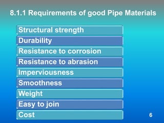
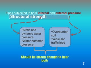
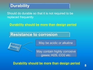
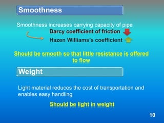
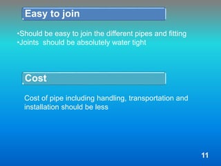
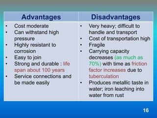
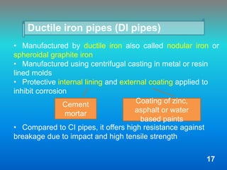
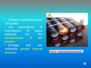
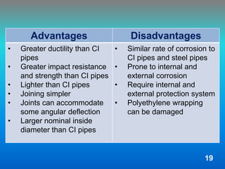
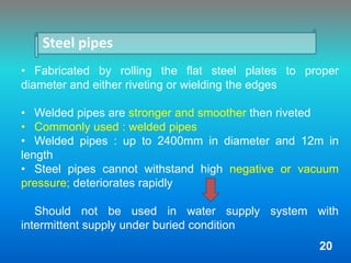
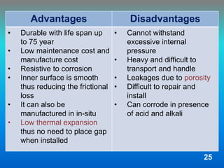
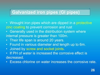
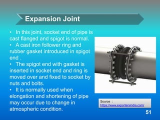
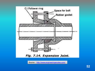
This document provides an overview of conveying water through pipelines. It discusses different types of pipe materials like cast iron, ductile iron, steel, concrete, galvanized iron and plastic pipes. The key requirements of good pipe materials are described as structural strength, durability, corrosion resistance, imperviousness, smoothness and cost. Different pipe joining methods like socket and spigot, flanged, screwed and expansion joints are also outlined. Finally, the major steps involved in laying pipes like setting out and trench excavation are briefly mentioned.
Booking open Available Pune Call Girls Pargaon 6297143586 Call Hot Indian Gi...
Conveyance of-water
1. Conveyance of Water
Group Members: Tutor:
Umesh, 187 Asst. Prof.Shukra Raj Paudel
Utsav, 188 Department Of Civil Engineering
Yogesh J, 189 IOE, Tribhuvan University
Yogesh SN, 191
Yubin,192
Shikhar, 193
2020-01-01
2. After this presentation students will be
able to learn about
oDifferent modes of water distribution and their
mechanism
oCharacteristics of a good pipe material and its
types
oManufacturing methods, properties, advantages
and disadvantages of different types of pipe
materials
oPipe material selection
oPipe networks and joints
oTypes of joints in pipe network and their
specifications
oSteps involved in laying of pipelines
1
3. Presentation Outline
8.1 Pipe Materials
8.1.1 Requirements of Good Pipe materials
8.1.2 Types of Pipe Materials
8.2 Pipe Joints
8.3 Laying of Pipes
2
4. Introduction on topic
Transportation of water form source to community
Use of various types of conduits : Gravity and Pressure
conduits
Gravity conduits include open channels, tunnel,
aqueducts etc
Pipelines belong to pressure conduits
Under gravity flow when
pipe do not run full
3
5. Comparison of conduits
Gravity conduit
• Flow under action of
gravity
• Water surface at
atmospheric pressure
• Designed as per the of
topography of the area
maintaining gradient
• Water safeguarding not
possible
• Generally used to convey
raw water from source to
treatment plant
Pressure conduit
• Flow under pressure
above atmospheric
pressure
• Can generally follow
shorter routes
• Fluid is not exposed and
hence, very less chances
of it getting polluted
• Water wasted in
percolation, evaporation,
etc is also saved
4
6. 8.1 Pipe Materials
Pipe is a circular closed conduit through which the fluid
flows
Different types of piping materials used for different uses,
including fresh water supply, waste drainage, irrigation etc
Piping material selection mainly depends on process
conditions such as
• Fluid it transports
• at what temperature
• at what pressure it transports.
5
7. 8.1.1 Requirements of good Pipe Materials
Structural strength
Durability
Resistance to corrosion
Resistance to abrasion
Imperviousness
Smoothness
Weight
Easy to join
Cost 6
8. Structural strength
Pipes subjected to both internal and external pressure
•Static and
dynamic water
pressure
•Water hammer
pressure
•Overburden
soil
•Vehicular
traffic load
Should be strong enough to bear
both
7
9. Durability
Should do durable so that it is not required to be
replaced frequently
Durability should be more than design period
Resistance to corrosion
May be acidic or alkaline
May contain highly corrosive
gases; H2S, CO2 etc.
Durability should be more than design period
8
10. Resistance to abrasion
Should possess enough resistance to abrasion
Imperviousness
Suspended
particles flowing
with high velocity
Erosion of inner
wall due to
abrasion
Should be able to prevent the admission of
wastewater and ground water into the pipe
source :
https://www.youtube.com/watch?v=_OEOeKTP
fKg
9
11. Smoothness
Should be smooth so that little resistance is offered
to flow
Weight
Should be light in weight
Smoothness increases carrying capacity of pipe
Darcy coefficient of friction
Hazen Williams’s coefficient
Light material reduces the cost of transportation and
enables easy handling
10
12. Easy to join
•Should be easy to join the different pipes and fitting
•Joints should be absolutely water tight
Cost
Cost of pipe including handling, transportation and
installation should be less
11
13. 8.1.2 Types of Pipe Materials
Cast iron pipes (CI pipes)
Ductile iron pipes (DI pipes)
Steel pipes
Cement concrete pipes
Galvanized iron pipes (GI pipes)
Plastic pipes
12
14. Cast iron pipes (CI pipes)
• Manufactured by pig iron
also called grey iron
• Can withstand high
internal pressure
• Offers high resistance
against corrosion
• Highly durable; lifespan of
around 100 years
Source : http://www.jaintubesmp.com/
13
15. Manufacturing method of CI pipes
Ordinary sand moulding
process
Molten metal poured into
sand line mould set either
vertical or horizontal
Expensive process and
used very less often
Centrifugal process
Pipes may be cast either
in a sand line mould or a
water
Moulds spun rapidly on a
horizontal axis while
molten metal is poured
Produces finer grained
and denser structure with
more uniform thickness
Most commonly used
14
16. Specifications of CI pipes
oGenerally cast in length of 3 to 6 meters
oIs classified as LA, A and B according to their
thickness
Class A : 10% more thickness
Class B : 20% more thickness
As
compared
to Class
LA
Maximum Hydraulic pressure resisting capacities :
Class LA 10 kg/cm2
Class A 12.5 kg/cm2
Class B 16 kg/cm2
15
17. Advantages Disadvantages
• Cost moderate
• Can withstand high
pressure
• Highly resistant to
corrosion
• Easy to join
• Strong and durable : life
span about 100 years
• Service connections and
be made easily
• Very heavy; difficult to
handle and transport
• Cost of transportation high
• Fragile
• Carrying capacity
decreases (as much as
70%) with time as friction
factor increases due to
tuberculation
• Produces metallic taste in
water; iron leaching into
water from rust
16
18. Ductile iron pipes (DI pipes)
• Manufactured by ductile iron also called nodular iron or
spheroidal graphite iron
• Manufactured using centrifugal casting in metal or resin
lined molds
• Protective internal lining and external coating applied to
inhibit corrosion
• Compared to CI pipes, it offers high resistance against
breakage due to impact and high tensile strength
Cement
mortar
Coating of zinc,
asphalt or water
based paints
17
19. • Lifespan estimated about
100 years
• Life expectancy of
unprotected DI pipes
depends on the
corrosiveness of soil
present
• stronger and can
withstand greater internal
pressure Source : https://m.made-in-china.com/
18
20. Advantages Disadvantages
• Greater ductility than CI
pipes
• Greater impact resistance
and strength than CI pipes
• Lighter than CI pipes
• Joining simpler
• Joints can accommodate
some angular deflection
• Larger nominal inside
diameter than CI pipes
• Similar rate of corrosion to
CI pipes and steel pipes
• Prone to internal and
external corrosion
• Require internal and
external protection system
• Polyethylene wrapping
can be damaged
19
21. Steel pipes
• Fabricated by rolling the flat steel plates to proper
diameter and either riveting or wielding the edges
• Welded pipes are stronger and smoother then riveted
• Commonly used : welded pipes
• Welded pipes : up to 2400mm in diameter and 12m in
length
• Steel pipes cannot withstand high negative or vacuum
pressure; deteriorates rapidly
Should not be used in water supply system with
intermittent supply under buried condition
20
23. Advantages Disadvantages
• Cheap
• Very strong to withstand
internal pressure
• Flexible to some extent
and can be laid easily on
curves
• Light and can easily be
handled and transported
• Available in long length
• Cannot withstand external
loads : earth fillings traffic
etc
• High maintenance cost
• More time required to
repair these pipes
• Likely to get rusted by
slightly acidic and alkaline
water
• Easily deformed by
combined actions of
external and internal loads
22
24. Cement concrete pipes
• Generally two types:
• Can be manufactured in factory known as precast pipe
and in field called in-situ pipes
• Precast pipes have superior quality than in-situ
• Precast reinforces pipes are known as Hume pipes
Plain cement concrete pipes which
can withstand head up to 15m
reinforced cement concrete pipes
which can withstand head up to
60m
23
26. Advantages Disadvantages
• Durable with life span up
to 75 year
• Low maintenance cost and
manufacture cost
• Resistive to corrosion
• Inner surface is smooth
thus reducing the frictional
loss
• It can also be
manufactured in in-situ
• Low thermal expansion
thus no need to place gap
when installed
• Cannot withstand
excessive internal
pressure
• Heavy and difficult to
transport and handle
• Leakages due to porosity
• Difficult to repair and
install
• Can corrode in presence
of acid and alkali
25
27. Galvanized iron pipes (GI pipes)
• Wrought iron pipes which are dipped in a protective
zinc coating to prevent corrosion and rust
• Generally used in the distribution system where
internal pressure is greater than 100m.
• Their life span is around 20 years.
• Found in various diameter and length up to 6m.
• Joined by screw and socket joints.
• If PH of water is increased the corrosive effect is
decreased.
• Excess chlorine on water increases the corrosive rate.
26
30. Advantages Disadvantages
• Cheap
• Light in weight and easy to
handle
• Easy to join
• Can be easily cut and
threaded
• Can withstand internal
pressure up to 180m
• Can expect to corrode due
to quality of water and soil.
• Less durable
• Pipes with diameter
greater than 80m are
costly
• Smoothness of pipes
decreases with time
29
31. Plastic pipes
• Obtained from the synthetic resin of high molecular
weight, polymerized from simple compounds by heat,
pressure and catalyst.
• Basic raw material is petroleum and natural gas.
Types of
Plastic
pipes
Polyethylene
(PE) pipes
Poly Vinyl
Chloride
(PVC) Pipes
Polypropylene
Random Copolymer
(PPR) Pipes
30
32. • Depending on the product quality there are high density
polyethylene(HDPE), medium density
polyethylene(MDPE), low density polyethylene(LDPE).
• Here density express the pressure that pipe can withstand
HDPE:
• Generally used in rural area of Nepal for gravity flow.
• Life span up to 100 years.
Polyethylene (PE) pipes
31
34. Advantages Disadvantages
• Cheap
• Durable and smooth
surface reduces the head
loss
• Available in different series
usable as per internal
pressure likely to be
encountered
• High impact strength
• Extremely strong, flexible,
chemical resistance,
corrosion free
• Easy to maintain
• Poor temperature
capability and not good to
carry hot water
• Poor weathering
resistance
• Flammable
33
35. • Most common constructing material for
plumbing application
• Made from combination of plastic and vinyl
• Inert and stable material that resist
corrosion
• Generally in white, brittle solid and are
insoluble in alcohol
• Most commonly used in water system,
underground wiring and sewer lines
• Maximum service temperature of 600C
Poly Vinyl Chloride (PVC) Pipes
34
37. Advantages Disadvantages
• Cheap
• Highly resistance to
corrosion
• Easy to join
• Durable with lifespan
around 50 years
• Smooth which reduces
loss of head due to friction
• Rust proof
• Brittle in nature
• Cannot be used for hot
water
• Not applicable for outdoor
application
• Less resistance to
weathering
36
38. • Thermoplastic resins produced through polymerization of
propylene, with ethylene link introduced in the polymer
chains.
• PPR fitting are most reliable in plumbing and water supply
due to fusion welding which ensure perfectly seal tight
system.
• It can be used for both hot and cold water.
• They are eco-friendly and recyclable.
Polypropylene Random Copolymer (PPR)
Pipes
37
40. Advantages Disadvantages
• Leak and frost proof
• Temperature resistance up
to 800C
• Good chemical resistance
and non-deforming
• Eco-friendly and
recyclable
• Lifespan more than 50
years
• Not applicable for outer
installation
• Difficult in repair as fusion
welding tool is required
• Painting should be done
before exposing to direct
sunlight
39
41. 8.2 Pipe Joints
• In water supply system a network of
long pipelines is required for the
conveyance of water.
• The pipes of small length is joined
together during pipe layout to develop
long pipe lines.
• The joints are therefore required to
join together the pipes of smaller
length.
• The selection of pipe joint however
depends on the pipe material, internal
pressure , durability, water tightness,
site condition, etc.
Source : https://www.123rf.com/
40
42. Types of Pipe Joints
Socket and Spigot Joint
Tyton Joint
Flanged Joint
Collar Joint
Screwed joint
Expansion Joint
41
43. Socket and Spigot Joint
• Also known as Bell and Spigot Joint or Run lead
Joint
• Enlarged end called Bell or Socket and Normal end
called spigot
• The annular space between socket and spigot filled
with molten lead
• The quantity of lead required per joint varies from
5kg for 150 mm diameter to 50kg for 1200 mm
diameter
• It is somewhat flexible joint
42
45. • This joint is also known as push on joint or push on
flexible joint.
• Rubber gasket is placed in the socket end of preceding
pipe and spigot end is inserted through gasket.
• More flexible than socket and spigot joint.
• Basically used for cast iron and ductile iron pipes.
Tyton Joint
Source :
https://hanyco.ir/
44
46. • Joint has flanges on both ends.
• A rubber gasket or washer, canvas or
lead is introduced between two flanges
to make it water tight.
• This joint is rigid and cannot be used
where deflection and vibration are
expected.
• Mostly used for temporary pipelines
such as pumping station, hydraulic
laboratories, etc.
• Commonly used to join the cast iron,
ductile iron , steel and galvanized iron
pipes.
Flanged Joint
45
Source :
https://www.indiamart.com/
48. Collar Joint
• It is made of reinforced concrete.
• The end of two pipes are brought
in contact at same level and rubber
gasket is placed in groove .
• The annular space between the
inside of collar and outside of pipe is
filled with 1:1 cement mortar.
• The outside of collar is finished at
angle of 45 degree.
• This joint is used for joining
cement concrete pipe with plane end.
47
Source :
https://www.tradeindia.com/
50. Screwed joint
• The ends of the pipe are plane
ends with screw threads on outer
surface and joint has a socket
which has screw threads on
inside.
• In order to make the joint water
proof a few strand of jute or hemp
and zinc white are placed on
threads.
• This joint is commonly used for
joining galvanized iron (GI) pipes.
49
Source :
http://www.greycastironcasting.com/
52. Expansion Joint
• In this joint, socket end of pipe is
cast flanged and spigot is normal.
• A cast iron follower ring and
rubber gasket introduced in spigot
end .
• The spigot end with gasket is
inserted in socket end and ring is
moved over and fixed to socket by
nuts and bolts.
• It is normally used when
elongation and shortening of pipe
may occur due to change in
atmospheric condition.
51
Source :
https://www.exportersindia.com/
54. 8.3 Laying of Pipes
• Started after completion of all survey and design
works, preparation of drawings and specifications and
procurement of materials
• Various steps involved:
1. Setting out
2. Excavation of trench
3. Timbering of trench
4. Preparation of sub-grade
5. Laying and joining of pipes
6. Testing of pipes
7. Backfilling of trench
8. Disinfection of pipeline
53
55. • Excavated along the alignment of pipeline to bury pipe
• Rectangular cross-section with width 30cm more than the
external diameter of pipe subjected to a minimum of 60cm
• Depth not less than 90cm from top of pipe and at joints
15cm more than normal depth
1. Setting out
2. Excavation of trench
• Process of transferring the points of pipe alignment from
drawing to the ground in site
• Theodolite, staffs, chain etc used
• Centre line marked on the ground by driving stakes 30m
apart on straight stretches and 7.5 – 15m apart on curves
54
56. • Done so that the pipe can be bedded true to the line and
gradient for its entire length on firm surface
• In soil where settlement is unlikely, sub-grade prepared by
simple ramming of layer of sand or clay
• In soil where settlement is likely, sub-grade prepared with
cement concrete bed of 15cm thickness over brick soiling
3. Timbering of trench
4. Preparation of sub-grade
• Done to prevent soil from caving out using wooden
planks which are supported by timber blocks, wedges and
struts
• Sometimes iron sheets used instead of wooden planks
• Not required in hard soil or soils where there is no
problem of caving out
55
57. 5. Laying and joining of pipes
• Small diameter pipes lowered in trench manually while
cranes and other mechanical devices used for larger
• Pipes should be wiped clean before laying
• Lowered carefully to have outer surface and ends
undamaged
• Pipes joined properly using suitable type of joints, valves,
etc
56
58. o Test consists of filling the pipeline slowly and carefully
with water, thus expelling air from within and leaving
water-full for few days
o Test pressure of about 0.5N/mm2 or the max working
pressure plus 50% more whichever is more is applied
o Open of pipeline temporarily closed to resist end thrust
of water pressure
o Manually operated test pump used in small pipes while
power driven test pump used in large or long pipes to
apply pressure
6. Testing of pipes
a) Pressure test
• After laying pressure and leakage tests carried out
• Length of pipeline to be tested should be less than or
equal to 500m
57
59. o After test pump delivers required pressure, it is stopped
and fall of pressure in pipeline is recorded
o If the pipeline maintains the test pressure without any
measurable loss of head for at least and hour: considered
satisfactory
b) Leakage test
o Initially pressure applied similar to pressure test
o Certain amount of water will be leaked from test section
after application of pressure
o After certain time, water added in pipe section to
maintain the specified leakage test pressure where
amount of water is the amount of water leaked
58
60. o Allowable leakage in pipeline given by:
Q =
Where, Q = allowable leakage in cm3/hr;
N = number of pipe joints in test section;
D = diameter of pipe in mm and;
P = applied test pressure in kg/cm2
ND √p
3.3
59
61. • Disinfection done by filling pipeline with chlorinated water
so that residue chlorine is of 50 mg/l is maintained for 12 hrs
• Then emptied, flushed with fresh water and put into
service
7. Backfilling of trench
8. Disinfection of pipeline
• Backfilling done in layers of 15 to 30cm thickness and
well rammed to restrict subsequent movement of pipe
• Sometimes done projecting 15cm above ground surface
which will be consolidated later by moving objects
60