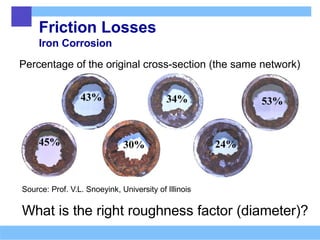
Friction Losses
Iron Corrosion
Percentageof the original cross-section (the same network)
Source: Prof. V.L. Snoeyink, University of Illinois
What is the right roughness factor (diameter)?
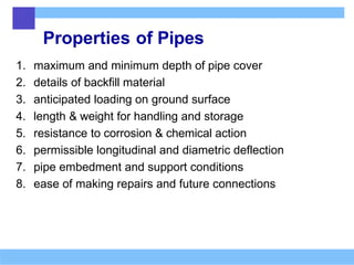
Properties of Pipes
1.maximum and minimum depth of pipe cover
2. details of backfill material
3. anticipated loading on ground surface
4. length & weight for handling and storage
5. resistance to corrosion & chemical action
6. permissible longitudinal and diametric deflection
7. pipe embedment and support conditions
8. ease of making repairs and future connections
5.
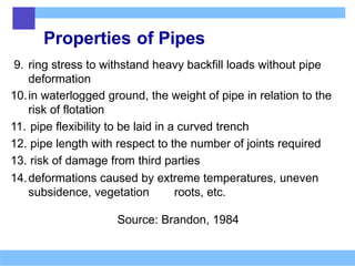
Properties of Pipes
9.ring stress to withstand heavy backfill loads without pipe
deformation
10.in waterlogged ground, the weight of pipe in relation to the
risk of flotation
11. pipe flexibility to be laid in a curved trench
12. pipe length with respect to the number of joints required
13. risk of damage from third parties
14.deformations caused by extreme temperatures, uneven
subsidence, vegetation roots, etc.
Source: Brandon, 1984
6.
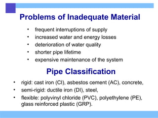
Problems of InadequateMaterial
• frequent interruptions of supply
• increased water and energy losses
• deterioration of water quality
• shorter pipe lifetime
• expensive maintenance of the system
Pipe Classification
• rigid: cast iron (CI), asbestos cement (AC), concrete,
• semi-rigid: ductile iron (DI), steel,
• flexible: polyvinyl chloride (PVC), polyethylene (PE),
glass reinforced plastic (GRP).
7.
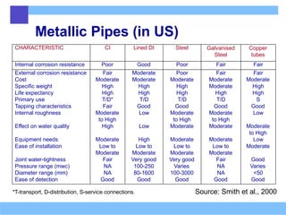
Metallic Pipes (inUS)
Source: Smith et al., 2000
*T-transport, D-distribution, S-service connections.
CHARACTERISTIC CI Lined DI Steel Galvanised
Steel
Copper
tubes
Internal corrosion resistance Poor Good Poor Fair Fair
External corrosion resistance Fair Moderate Poor Fair Fair
Cost Moderate Moderate Moderate Moderate Moderate
Specific weight High High High Moderate High
Life expectancy High High High High High
Primary use T/D* T/D T/D T/D S
Tapping characteristics Fair Good Good Good Good
Internal roughness Moderate Low Moderate Moderate Low
to High to High to High
Effect on water quality High Low Moderate Moderate Moderate
to High
Equipment needs Moderate High Moderate Moderate Low
Ease of installation Low to Low to Low to Low to Moderate
Moderate Moderate Moderate Moderate
Joint water-tightness Fair Very good Very good Fair Good
Pressure range (mwc) NA 100-250 Varies NA Varies
Diameter range (mm) NA 80-1600 100-3000 NA <50
Ease of detection Good Good Good Good Good
8.
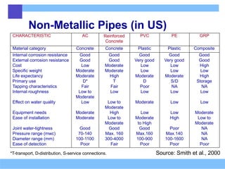
Non-Metallic Pipes (inUS)
Source: Smith et al., 2000
*T-transport, D-distribution, S-service connections.
CHARACTERISTIC AC Reinforced
Concrete
PVC PE GRP
Material category Concrete Concrete Plastic Plastic Composite
Internal corrosion resistance Good Good Good Good Good
External corrosion resistance Good Good Very good Very good Good
Cost Low Moderate Low Low High
Specific weight Moderate Moderate Low Low Low
Life expectancy Moderate High Moderate Moderate High
Primary use D* T D S/D Storage
Tapping characteristics Fair Fair Poor NA NA
Internal roughness Low to Low Low Low Low
Moderate
Effect on water quality Low Low to Moderate Low Low
Moderate
Equipment needs Moderate High Low Low Moderate
Ease of installation Moderate Low to Moderate High Low to
Moderate to High Moderate
Joint water-tightness Good Good Good Poor NA
Pressure range (mwc) 70-140 Max. 160 Max.160 Max.140 NA
Diameter range (mm) 100-1100 300-4000 100-900 100-1600 NA
Ease of detection Poor Fair Poor Poor Poor
9.
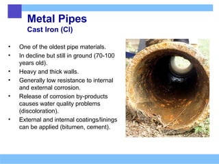
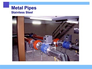
Metal Pipes
Cast Iron(CI)
• One of the oldest pipe materials.
• In decline but still in ground (70-100
years old).
• Heavy and thick walls.
• Generally low resistance to internal
and external corrosion.
• Release of corrosion by-products
causes water quality problems
(discoloration).
• External and internal coatings/linings
can be applied (bitumen, cement).
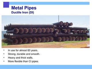
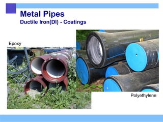
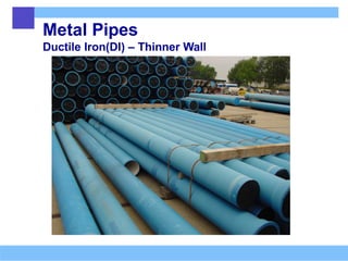
Metal Pipes
Ductile Iron(DI)
• In use for almost 60 years.
• Strong, durable and smooth.
• Heavy and thick walls.
• More flexible than CI pipes.
12.
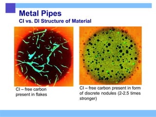
Metal Pipes
CI vs.DI Structure of Material
CI – free carbon
present in flakes
CI – free carbon present in form
of discrete nodules (2-2.5 times
stronger)
13.
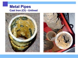
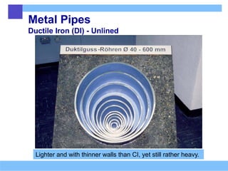
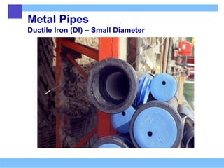
Metal Pipes
Ductile Iron(DI) - Unlined
Lighter and with thinner walls than CI, yet still rather heavy.
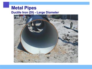
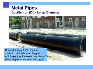
Metal Pipes
Ductile Iron(DI) - Large Diameter
Due to its weight, DI pipes are
made in relatively short lengths
which requires increased number of
joints (higher chance for leakage).
20.
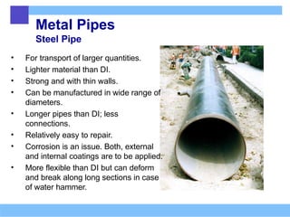
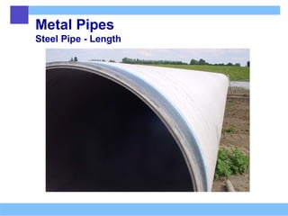
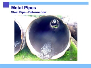
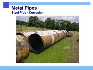
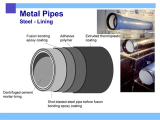
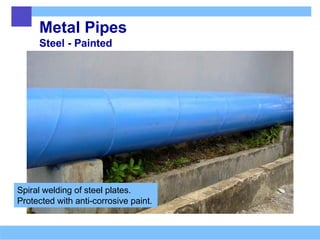
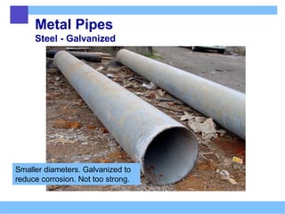
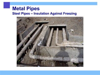
Metal Pipes
Steel Pipe
•For transport of larger quantities.
• Lighter material than DI.
• Strong and with thin walls.
• Can be manufactured in wide range of
diameters.
• Longer pipes than DI; less
connections.
• Relatively easy to repair.
• Corrosion is an issue. Both, external
and internal coatings are to be applied.
• More flexible than DI but can deform
and break along long sections in case
of water hammer.
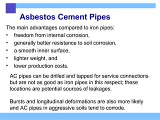
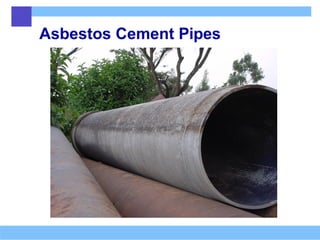
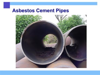
Asbestos Cement Pipes
Themain advantages compared to iron pipes:
• freedom from internal corrosion,
• generally better resistance to soil corrosion,
• a smooth inner surface,
• lighter weight, and
• lower production costs.
AC pipes can be drilled and tapped for service connections
but are not as good as iron pipes in this respect; these
locations are potential sources of leakages.
Bursts and longitudinal deformations are also more likely
and AC pipes in aggressive soils tend to corrode.
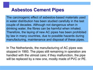
Asbestos Cement Pipes
Thecarcinogenic effect of asbestos-based materials used
in water distribution has been studied carefully in the last
couple of decades. Although not dangerous when in
drinking water, the fibres can be harmful when inhaled.
Therefore, the laying of new AC pipes has been prohibited
by law in many countries, due to possible hazards during
manufacturing, maintenance and disposal of these pipes.
In The Netherlands, the manufacturing of AC pipes was
stopped in 1993. The pipes still remaining in operation are
handled with the utmost care; if they malfunction, the pipe
will be replaced by a new one, mostly made of PVC or PE.
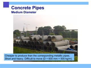
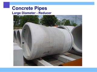
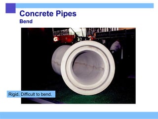
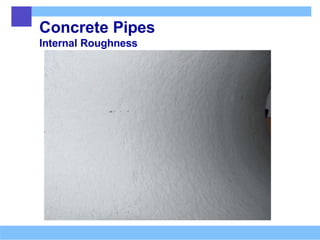
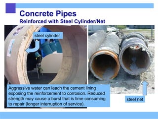
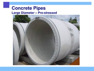
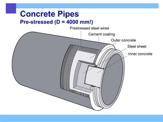
Concrete Pipes
Reinforced withSteel Cylinder/Net
steel cylinder
steel net
Aggressive water can leach the cement lining
exposing the reinforcement to corrosion. Reduced
strength may cause a burst that is time consuming
to repair (longer interruption of service).
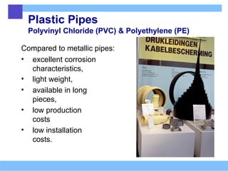
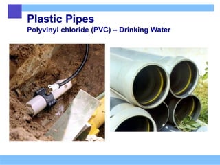
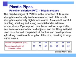
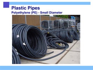
Plastic Pipes
Polyvinyl chloride(PVC) – Disadvantages
The disadvantages of PVC lie in the reduction of its impact
strength in extremely low temperatures, and of its tensile
strength in extremely high temperatures. As a result, careful
handling, stacking and laying is crucial under extreme
temperatures. Pipe support must be as uniform as possible,
free from stones or other hard objects, and the filling material
used must be well compacted. A fracture can develop into a
split along considerable lengths of the pipe, resulting in large
water losses.
Source: Mays, 2000
Service temperature (º C) 27 32 38 43 49 54 60
Percentage of original
pressure rating
88 75 62 50 40 30 22
47.
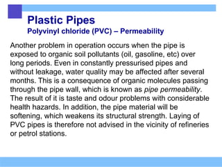
Plastic Pipes
Polyvinyl chloride(PVC) – Permeability
Another problem in operation occurs when the pipe is
exposed to organic soil pollutants (oil, gasoline, etc) over
long periods. Even in constantly pressurised pipes and
without leakage, water quality may be affected after several
months. This is a consequence of organic molecules passing
through the pipe wall, which is known as pipe permeability.
The result of it is taste and odour problems with considerable
health hazards. In addition, the pipe material will be
softening, which weakens its structural strength. Laying of
PVC pipes is therefore not advised in the vicinity of refineries
or petrol stations.
48.
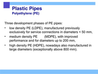
Plastic Pipes
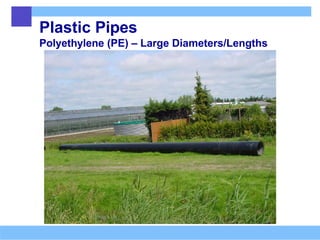
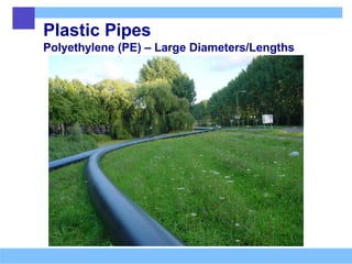
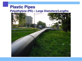
Polyethylene (PE)
Threedevelopment phases of PE pipes:
• low density PE (LDPE), manufactured previously
exclusively for service connections in diameters < 50 mm,
• medium density PE (MDPE), with improved
performance and for diameters up to 200 mm,
• high density PE (HDPE), nowadays also manufactured in
large diameters (exceptionally above 800 mm).
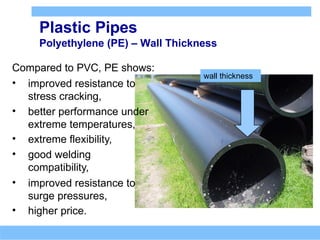
Plastic Pipes
Polyethylene (PE)– Wall Thickness
wall thickness
Compared to PVC, PE shows:
• improved resistance to
stress cracking,
• better performance under
extreme temperatures,
• extreme flexibility,
• good welding
compatibility,
• improved resistance to
surge pressures,
• higher price.
51.
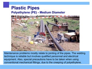
Plastic Pipes
Polyethylene (PE)- Medium Diameter
Maintenance problems mostly relate to jointing of the pipes. The welding
technique is reliable but involves qualified personnel and electrical
equipment. Also, special precautions have to be taken when using
conventional mechanical fittings, due to the creeping of polyethylene.
52.
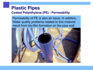
Plastic Pipes
Coated Polyethylene(PE) - Permeability
Permeability of PE is also an issue. In addition,
Water quality problems related to this material
result from bio-film formation on the pipe wall.
Plastic Pipes
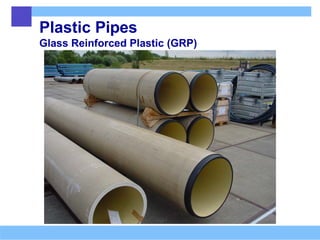
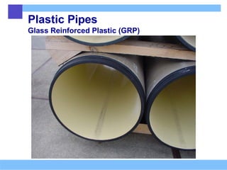
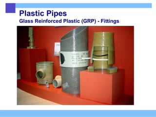
Glass ReinforcedPlastic (GRP)
• Manufactured in larger diameters.
• Compared to concrete and steel pipes of the
same diameter, they are lighter in weight,
• more flexible,
• more resistant to corrosion,
• have higher price and therefore,
• not as frequently used for drinking water transport
as the other pipe materials.
Environmental Aspects ofPipes
Due to their massive use, pipe materials should be
judged not only from the perspective of their
performance but also on the effects they cause on the
environment either during manufacturing or in the
post-exploitation phase.
A typical example is PVC, which is considered to be a
favourable pipe material but which emits some
carcinogenic pollutants during manufacturing
processes.
62.
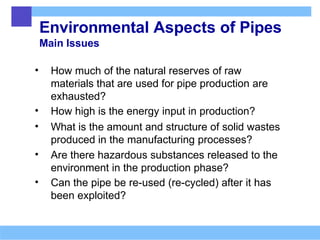
Environmental Aspects ofPipes
Main Issues
• How much of the natural reserves of raw
materials that are used for pipe production are
exhausted?
• How high is the energy input in production?
• What is the amount and structure of solid wastes
produced in the manufacturing processes?
• Are there hazardous substances released to the
environment in the production phase?
• Can the pipe be re-used (re-cycled) after it has
been exploited?
63.
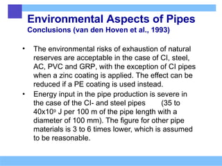
Environmental Aspects ofPipes
Conclusions (van den Hoven et al., 1993)
• The environmental risks of exhaustion of natural
reserves are acceptable in the case of CI, steel,
AC, PVC and GRP, with the exception of CI pipes
when a zinc coating is applied. The effect can be
reduced if a PE coating is used instead.
• Energy input in the pipe production is severe in
the case of the CI- and steel pipes (35 to
40x109 J per 100 m of the pipe length with a
diameter of 100 mm). The figure for other pipe
materials is 3 to 6 times lower, which is assumed
to be reasonable.
64.
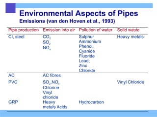
Environmental Aspects ofPipes
Emissions (van den Hoven et al., 1993)
Pipe production Emission into air Pollution of water Solid waste
CI, steel CO2
SO2
NOx
Sulphur
Ammonium
Phenol,
Cyanide
Fluoride
Lead,
Zinc
Chloride
Heavy metals
AC AC fibres
PVC SO2,NOx
Chlorine
Vinyl
chloride
Vinyl Chloride
GRP Heavy
metals Acids
Hydrocarbon
65.
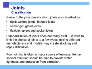
Joints
Classification
Similar to thepipe classification, joints are classified as:
• rigid: welded joints, flanged joints
• semi-rigid: gland joints
• flexible: spigot and socket joints
Standardisation of joints does not really exist. It is wise to
limit the choice of joints to a few types; mixing different
manufacturers and models may create stocking and
repair difficulties.
Poor jointing is often a major source of leakage. Hence,
special attention should be paid to provide water
tightness and protection from corrosion.
66.
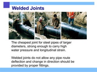
Welded Joints
The cheapestjoint for steel pipes of larger
diameters, strong enough to carry high
water pressure and longitudinal strain.
Welded joints do not allow any pipe route
deflection and change in direction should be
provided by proper fittings.
67.
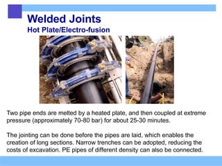
Welded Joints
Hot Plate/Electro-fusion
Twopipe ends are melted by a heated plate, and then coupled at extreme
pressure (approximately 70-80 bar) for about 25-30 minutes.
The jointing can be done before the pipes are laid, which enables the
creation of long sections. Narrow trenches can be adopted, reducing the
costs of excavation. PE pipes of different density can also be connected.
68.
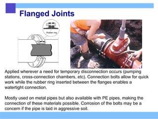
Flanged Joints
Applied wherevera need for temporary disconnection occurs (pumping
stations, cross-connection chambers, etc). Connection bolts allow for quick
work while the rubber ring inserted between the flanges enables a
watertight connection.
Mostly used on metal pipes but also available with PE pipes, making the
connection of these materials possible. Corrosion of the bolts may be a
concern if the pipe is laid in aggressive soil.
69.
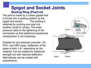
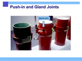
Spigot and SocketJoints
Sealing Ring (Push-in)
The joint is made by a rubber gasket that
is forced into a sealing position by the
spigot and socket. The jointing is
obtained by pushing one pipe into
another (‘push-in’ joints). The water
pressure adds to the tightening of the
connection so that additional mechanical
compression is not necessary.
Suitable for pre-stressed concrete-, DI-,
PVC- and GRP pipes. Deflection of the
pipes is from 1-5o, depending on the
material. Can be welded for additional
strength but with reduced deflection.
Alternatively can be coated with
polyethylene.
70.
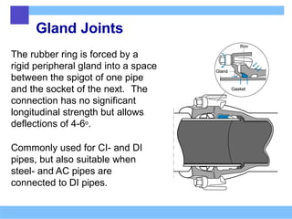
Gland Joints
The rubberring is forced by a
rigid peripheral gland into a space
between the spigot of one pipe
and the socket of the next. The
connection has no significant
longitudinal strength but allows
deflections of 4-6o.
Commonly used for CI- and DI
pipes, but also suitable when
steel- and AC pipes are
connected to DI pipes.
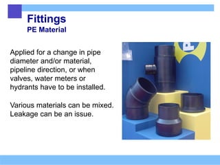
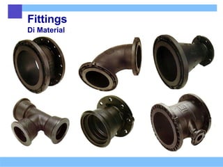
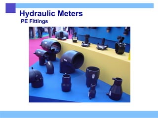
Fittings
PE Material
Applied fora change in pipe
diameter and/or material,
pipeline direction, or when
valves, water meters or
hydrants have to be installed.
Various materials can be mixed.
Leakage can be an issue.
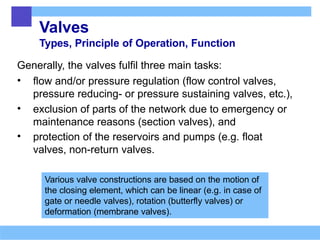
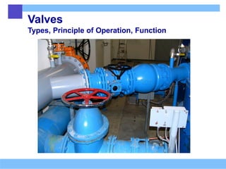
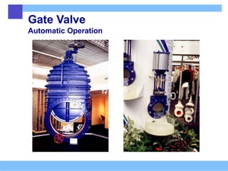
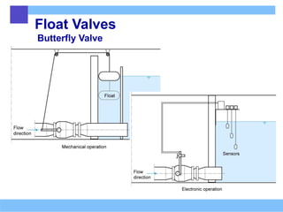
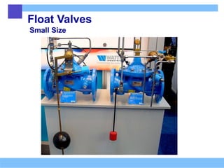
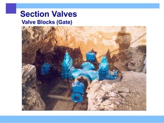
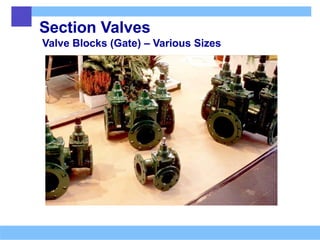
Valves
Types, Principle ofOperation, Function
Generally, the valves fulfil three main tasks:
• flow and/or pressure regulation (flow control valves,
pressure reducing- or pressure sustaining valves, etc.),
• exclusion of parts of the network due to emergency or
maintenance reasons (section valves), and
• protection of the reservoirs and pumps (e.g. float
valves, non-return valves.
Various valve constructions are based on the motion of
the closing element, which can be linear (e.g. in case of
gate or needle valves), rotation (butterfly valves) or
deformation (membrane valves).
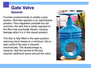
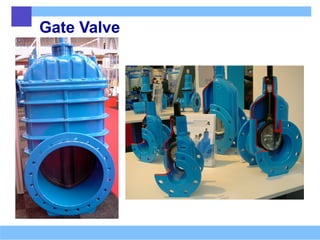
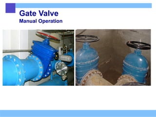
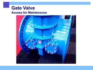
Gate Valve
General
Function predominantlyto isolate a pipe
section. Normally operate in an open/closed
position. Flow regulation possible but not
common; the disk that is partly exposed to
the flow may eventually loosen, causing
leakage when it is in the closed position.
The disc is fully lifted in the open position
reducing minor losses to a minimum; this is
also useful if the pipe is cleaned
mechanically. The disadvantage is,
however, that the bonnet of the disc
requires additional space around the valve.
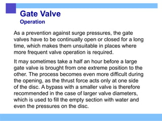
Gate Valve
Operation
As aprevention against surge pressures, the gate
valves have to be continually open or closed for a long
time, which makes them unsuitable in places where
more frequent valve operation is required.
It may sometimes take a half an hour before a large
gate valve is brought from one extreme position to the
other. The process becomes even more difficult during
the opening, as the thrust force acts only at one side
of the disc. A bypass with a smaller valve is therefore
recommended in the case of larger valve diameters,
which is used to fill the empty section with water and
even the pressures on the disc.
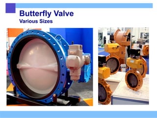
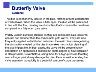
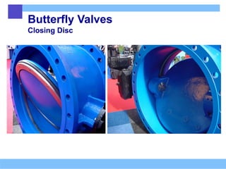
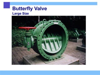
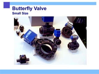
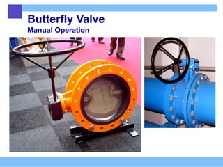
Butterfly Valve
General
The discis permanently located in the pipe, rotating around a horizontal
or vertical axis. When the valve is fully open, the disc will be positioned
in line with the flow, creating an obstruction that increases the head-loss
compared to a fully open gate valve.
Widely used in pumping stations as they are compact in size, easier to
operate and cheaper than the comparable gate valves. They are also
frequently applied in distribution networks, the main disadvantage being
the obstruction created by the disc that makes mechanical cleaning of
the pipe impossible. In both cases, the valve will be predominantly
operated in an open/closed position but some degree of flow regulation
is also possible. Nevertheless, using them for a high-pressure throttling
over a longer period may damage the disc. Here as well, operating the
valve operation too quickly is a potential source of surge pressures.
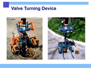
Valve Regeneration
The numberof section valves in any sizable
distribution system can be huge, with the vast
majority of them not being frequently operated.
An automatic device with an adjustable turning
speed can be used in cases where many valves
have to be operated within a short period of time.
Occasional turning of valves, known as valve
regeneration, is a part of regular network
maintenance in order to prevent clogging of the
mechanism.
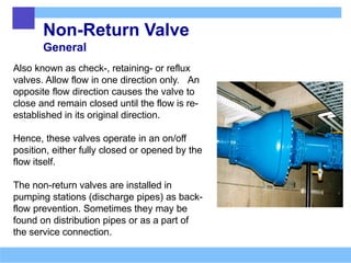
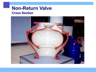
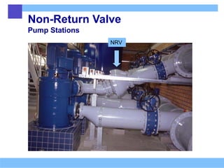
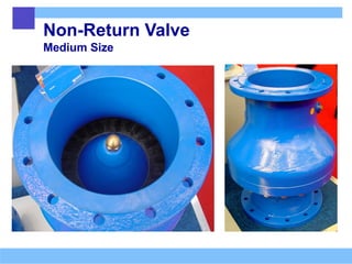
Non-Return Valve
General
Also knownas check-, retaining- or reflux
valves. Allow flow in one direction only. An
opposite flow direction causes the valve to
close and remain closed until the flow is re-
established in its original direction.
Hence, these valves operate in an on/off
position, either fully closed or opened by the
flow itself.
The non-return valves are installed in
pumping stations (discharge pipes) as back-
flow prevention. Sometimes they may be
found on distribution pipes or as a part of
the service connection.
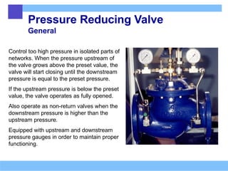
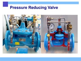
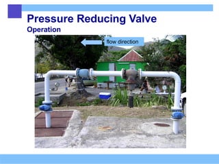
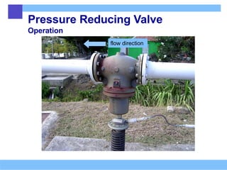
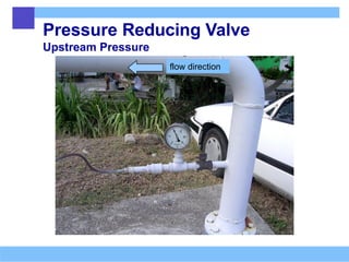
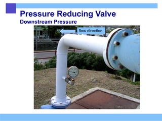
Pressure Reducing Valve
General
Controltoo high pressure in isolated parts of
networks. When the pressure upstream of
the valve grows above the preset value, the
valve will start closing until the downstream
pressure is equal to the preset pressure.
If the upstream pressure is below the preset
value, the valve operates as fully opened.
Also operate as non-return valves when the
downstream pressure is higher than the
upstream pressure.
Equipped with upstream and downstream
pressure gauges in order to maintain proper
functioning.
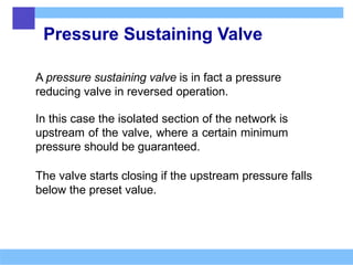
Pressure Sustaining Valve
Apressure sustaining valve is in fact a pressure
reducing valve in reversed operation.
In this case the isolated section of the network is
upstream of the valve, where a certain minimum
pressure should be guaranteed.
The valve starts closing if the upstream pressure falls
below the preset value.
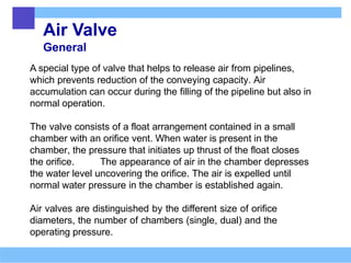
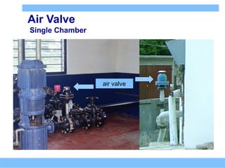
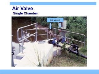
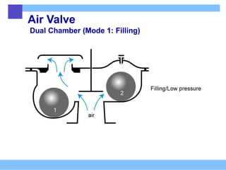
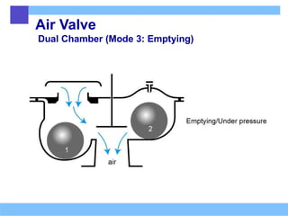
Air Valve
General
A specialtype of valve that helps to release air from pipelines,
which prevents reduction of the conveying capacity. Air
accumulation can occur during the filling of the pipeline but also in
normal operation.
The valve consists of a float arrangement contained in a small
chamber with an orifice vent. When water is present in the
chamber, the pressure that initiates up thrust of the float closes
the orifice. The appearance of air in the chamber depresses
the water level uncovering the orifice. The air is expelled until
normal water pressure in the chamber is established again.
Air valves are distinguished by the different size of orifice
diameters, the number of chambers (single, dual) and the
operating pressure.
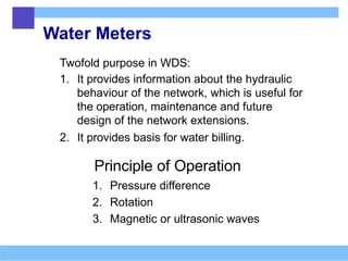
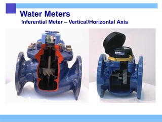
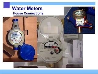
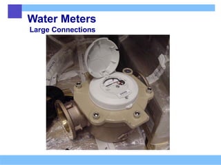
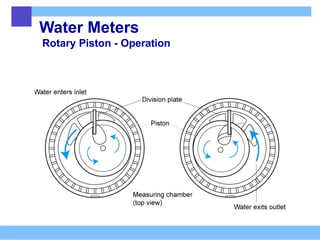
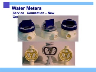
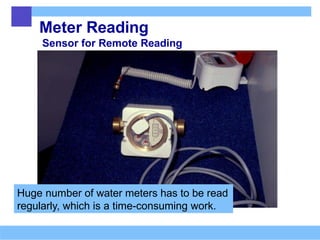
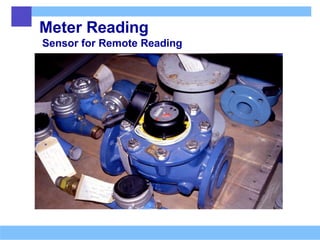
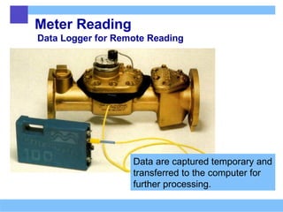
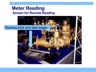
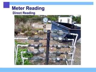
Water Meters
Twofold purposein WDS:
1. It provides information about the hydraulic
behaviour of the network, which is useful for
the operation, maintenance and future
design of the network extensions.
2. It provides basis for water billing.
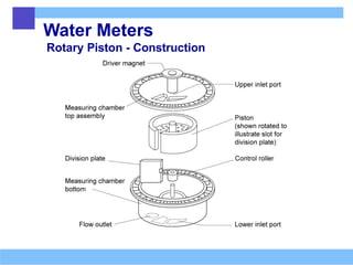
Principle of Operation
1. Pressure difference
2. Rotation
3. Magnetic or ultrasonic waves
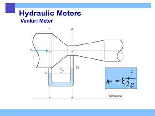
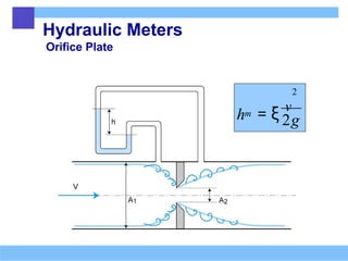
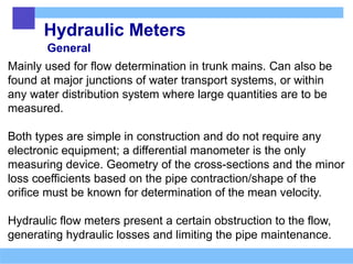
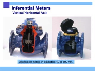
Hydraulic Meters
General
Mainly usedfor flow determination in trunk mains. Can also be
found at major junctions of water transport systems, or within
any water distribution system where large quantities are to be
measured.
Both types are simple in construction and do not require any
electronic equipment; a differential manometer is the only
measuring device. Geometry of the cross-sections and the minor
loss coefficients based on the pipe contraction/shape of the
orifice must be known for determination of the mean velocity.
Hydraulic flow meters present a certain obstruction to the flow,
generating hydraulic losses and limiting the pipe maintenance.
119.
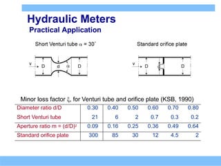
Hydraulic Meters
Practical Application
Minorloss factor ξ, for Venturi tube and orifice plate (KSB, 1990)
Diameter ratio d/D 0.30 0.40 0.50 0.60 0.70 0.80
Short Venturi tube 21 6 2 0.7 0.3 0.2
Aperture ratio m = (d/D)2 0.09 0.16 0.25 0.36 0.49 0.64
Standard orifice plate 300 85 30 12 4.5 2
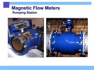
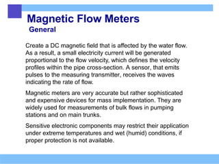
Magnetic Flow Meters
General
Createa DC magnetic field that is affected by the water flow.
As a result, a small electricity current will be generated
proportional to the flow velocity, which defines the velocity
profiles within the pipe cross-section. A sensor, that emits
pulses to the measuring transmitter, receives the waves
indicating the rate of flow.
Magnetic meters are very accurate but rather sophisticated
and expensive devices for mass implementation. They are
widely used for measurements of bulk flows in pumping
stations and on main trunks.
Sensitive electronic components may restrict their application
under extreme temperatures and wet (humid) conditions, if
proper protection is not available.
Ultrasonic Flow Meters
GeneralPrinciple
Make use of ultrasonic waves to sample the velocity profile within
the pipe. Commonly based on the transit time principle, which takes
the speed of sound propagation in water into account. Two sound
transducers are installed along a short pipe distance, exchanging
the diagonal sound waves in opposite directions.
The difference between the sound frequencies of the two signals,
which is proportional to the flow rate, will be registered because the
sound travelling against the flow will need more time to reach the
receiver than the one travelling with the flow.
If the transducers are installed on the opposite side of the pipe, the
wave exchange will be straight. However, they are more frequently
installed on the same side of the pipe creating a refraction of the
emitted wave from the pipe wall prior to being received by the
opposite transducer, which increases the accuracy of measuring.
126.
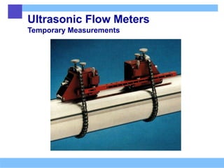
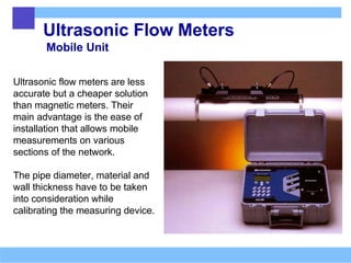
Ultrasonic Flow Meters
MobileUnit
Ultrasonic flow meters are less
accurate but a cheaper solution
than magnetic meters. Their
main advantage is the ease of
installation that allows mobile
measurements on various
sections of the network.
The pipe diameter, material and
wall thickness have to be taken
into consideration while
calibrating the measuring device.
Indoor
Installations
High Buildings
High buildingsare supplied from
the distribution system only
partially, at lower floors.
Internal booster installation is to be
provided to lift the water to the
higher floors.
A tank can be installed on the roof
for supply of the top floors and
also for fire fighting purposes.
152.
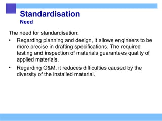
Standardisation
Need
The need forstandardisation:
• Regarding planning and design, it allows engineers to be
more precise in drafting specifications. The required
testing and inspection of materials guarantees quality of
applied materials.
• Regarding O&M, it reduces difficulties caused by the
diversity of the installed material.
153.
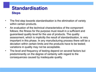
Standardisation
Steps
• The firststep towards standardisation is the elimination of variety
within certain products.
• An evaluation of the technical characteristics of the component
follows; the fitness for the purpose must result in a sufficient and
guaranteed quality level for the use of products. The quality
assessment, which is implicitly the result of standardisation, is very
important in this phase. In any manufacturing process there will be a
deviation within certain limits and the products have to be tested;
variations in quality may not be acceptable.
• The level and frequency of testing depend on several factors but
predominantly on the degree of certainty with regard to the
consequences caused by inadequate quality.
154.
Testing
Principles
Basically three differentprinciples:
• batch testing; a product sample is tested and a verdict on its
compatibility with the specifications is issued.
• testing and assessment by the manufacturer’s internal control,
followed by surveillance; a sample testing of the product according to
a prescribed method approved by the manufacturer’s quality control.
This testing is regularly followed by surveillance in the form of quality
control in the factory, but also by audit testing from both the factory
and open market.
• internal assessment by the manufacturer; concerns the manufacturer’s
capability to produce consistently in accordance with required
specifications. The manufacturing methods, facilities and quality
control are assessed and approved in respect of a discrete technology
that is capable of delivering products of constant quality .
155.
Centralisation of Testing
Need
•Centralisation of testing can be obtained by
establishing an institution that will assist the water
sector with services related to quality control.
This offers obvious advantages:
• lower expenses for quality control,
• availability of proper equipment at the required
time,
• continuity of testing and inspection,
• development of experience in the field,
• the exchange of information.
156.
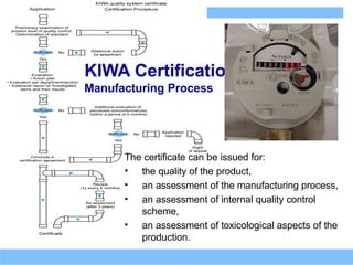
KIWA Certification
Manufacturing Process
Thecertificate can be issued for:
• the quality of the product,
• an assessment of the manufacturing process,
• an assessment of internal quality control
scheme,
• an assessment of toxicological aspects of the
production.


![Pipe materials and types of joints [autosaved]](https://cdn.slidesharecdn.com/ss_thumbnails/pipematerialsandtypesofjointsautosaved-180719140405-thumbnail.jpg?width=640&height=640&fit=bounds)


