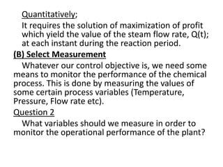
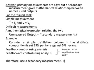
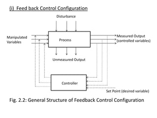
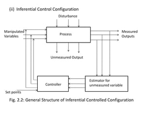
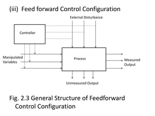
The document provides an overview of process dynamics and control, focusing on the design and hardware aspects of control systems in chemical processes. It discusses the classification of variables, design elements for control objectives, the selection of measurement and control configurations, and the development of controllers. Key hardware elements involved in process control, including sensors, transducers, controllers, and the impact of digital computers, are also highlighted.
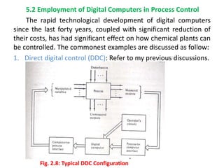
![Diagrammatically
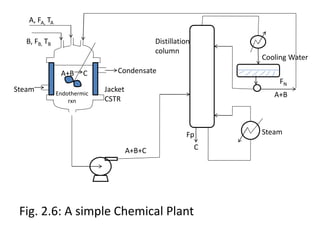
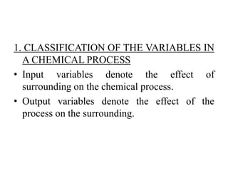
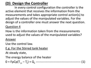
How T changes with time will be given by the
transient energy balance around the tank; that is
Subtracting eqn 1 from eqn 2, we have
Note that, since Ts = constant
Time
Ts
Ti,s
Ti
dT/dt
=
))/dt
T
-
(d(T s
(3
-
-
-
Qs)
-
(Q
+
Ts)]
-
(T
-
s)
Ti,
-
Cp[(Ti
F
=
Ts))/dt
-
Cp(d(T
V
(2)
-
-
-
-
Q
+
T)
-
Cp(Ti
F
=
d(T)/dt
Cp
V
](https://image.slidesharecdn.com/pdcmodule2-240703145538-ecae1d55/85/Presentation-on-process-dynamics-and-control-17-320.jpg)
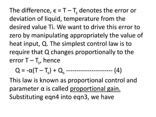
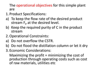
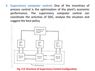
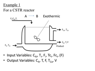
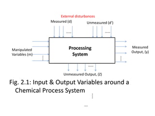
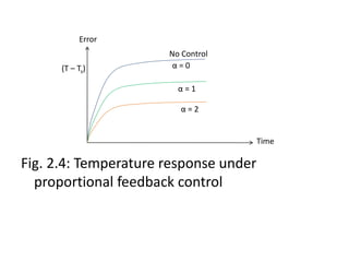
![VρCp d(T – Ts)/dt = FρCp[(Ti – Ti,s) – (T – Ts)] – α(T – Ts) -------- (5)
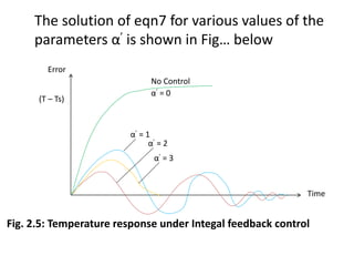
Eqn5 is solved for (T – Ts), and for various values
of gain and yield the solutions shown in Fig..
below. It’s noticed that more of the solutions is
satisfactory since T – Ts ≠ 0. Thus one concludes
that the proportional control law is not
acceptable.](https://image.slidesharecdn.com/pdcmodule2-240703145538-ecae1d55/85/Presentation-on-process-dynamics-and-control-19-320.jpg)
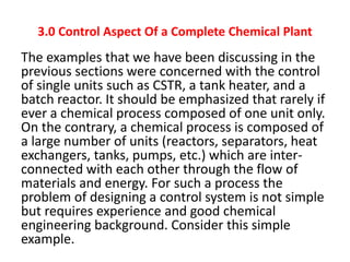
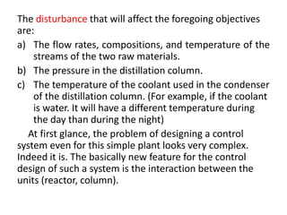
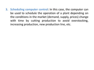
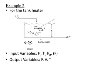
![However, considerable improvement in the
quality of the resulting control can be obtained
if one uses a different control law known as
integral control. In this case Q is proportional to
the time integral of (T – Ts); thus,
Substituting again Q from eqn6 into eqn3, we
have
(6)
-
-
-
-
-
-
-
-
-
Qs
+
Ts)dt
-
(T
'
t
0
Q
)
7
(
Ts)dt
-
(T
'
-
]
Ts)
-
(T
-
s)
Ti,
-
Cp[(Ti
F
=
Ts))/dt
-
(d(T
Cp
V
t
0
](https://image.slidesharecdn.com/pdcmodule2-240703145538-ecae1d55/85/Presentation-on-process-dynamics-and-control-21-320.jpg)