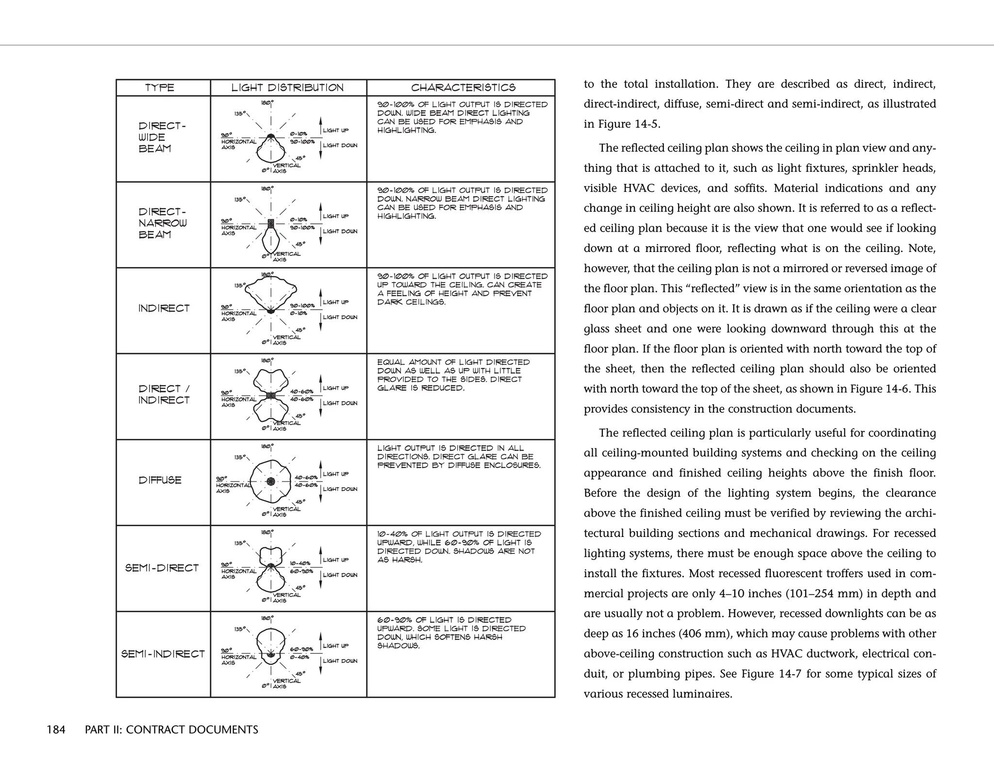
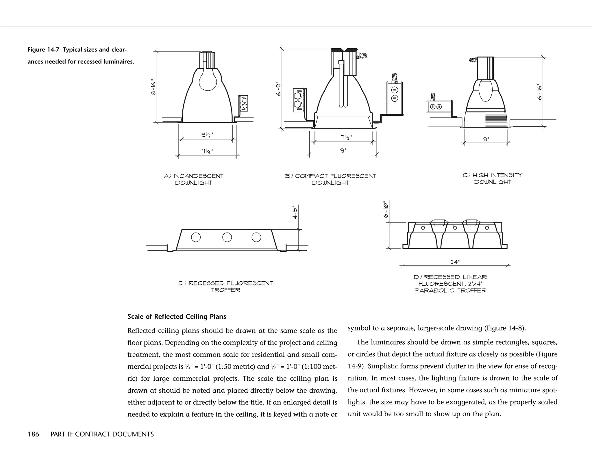
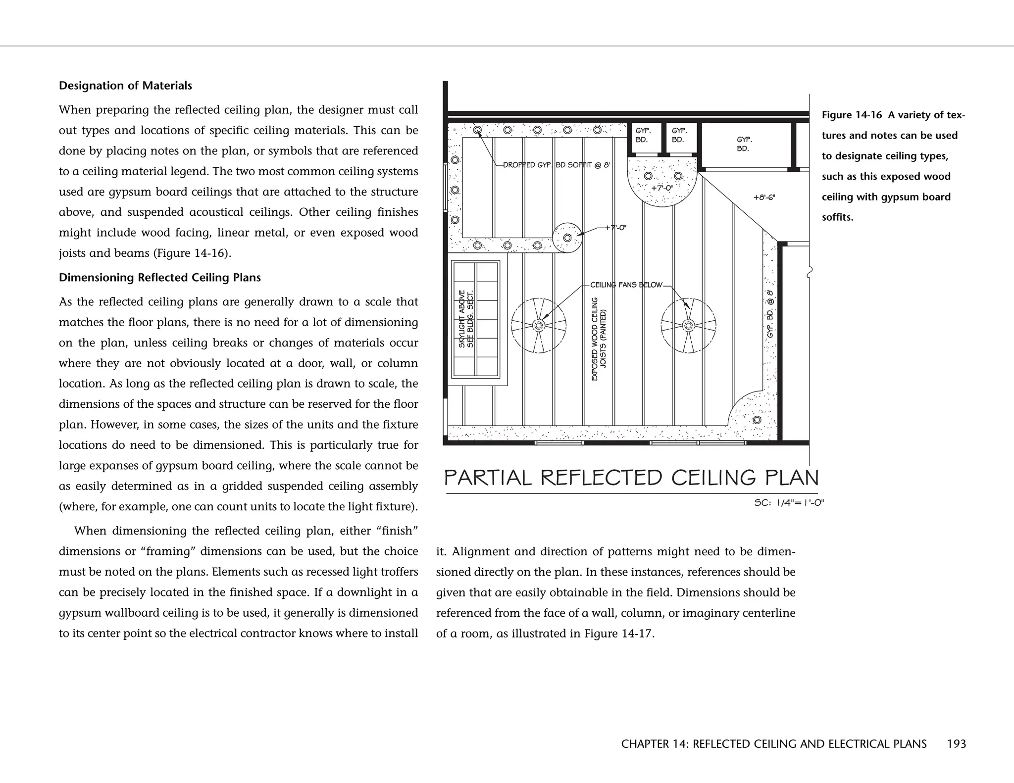
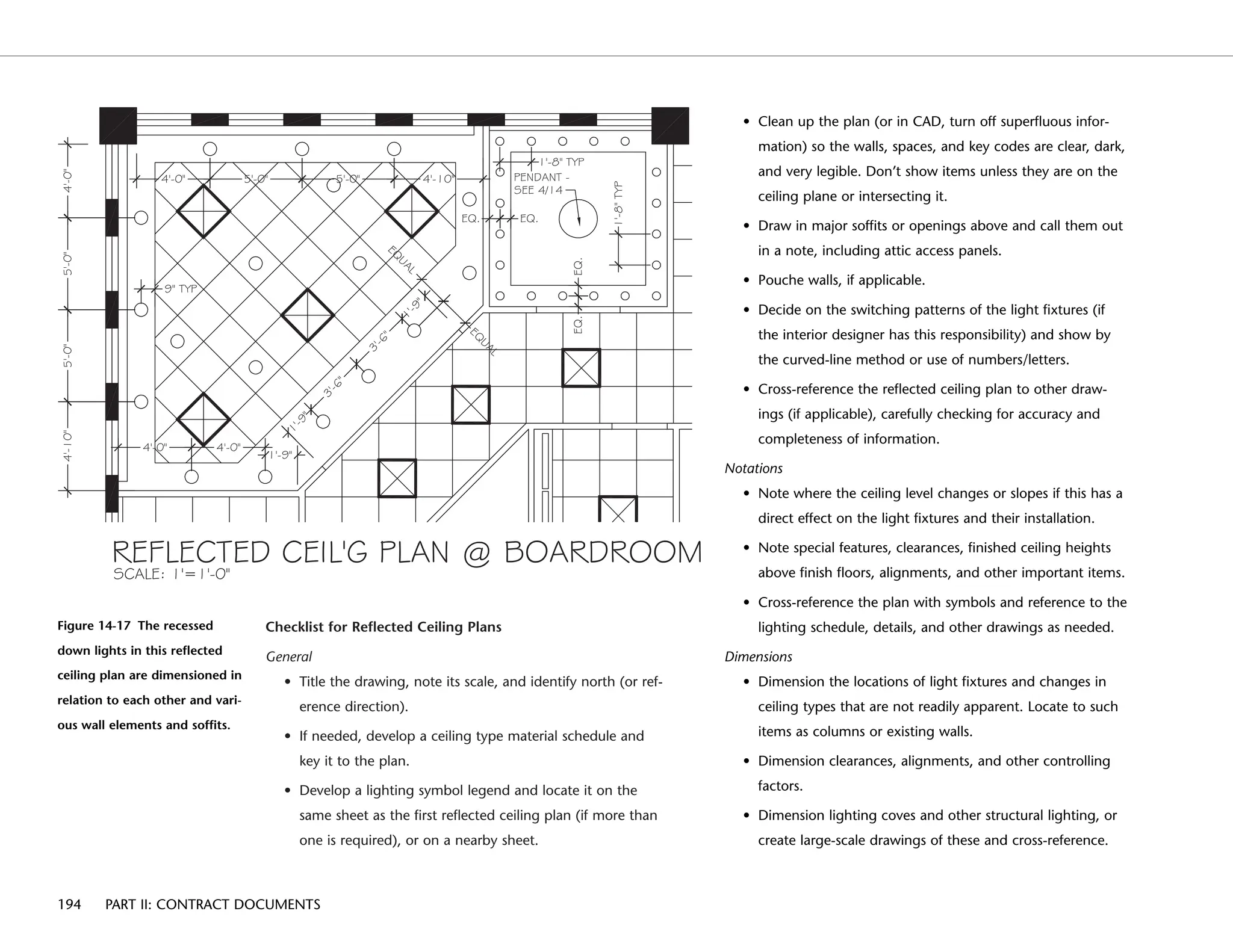
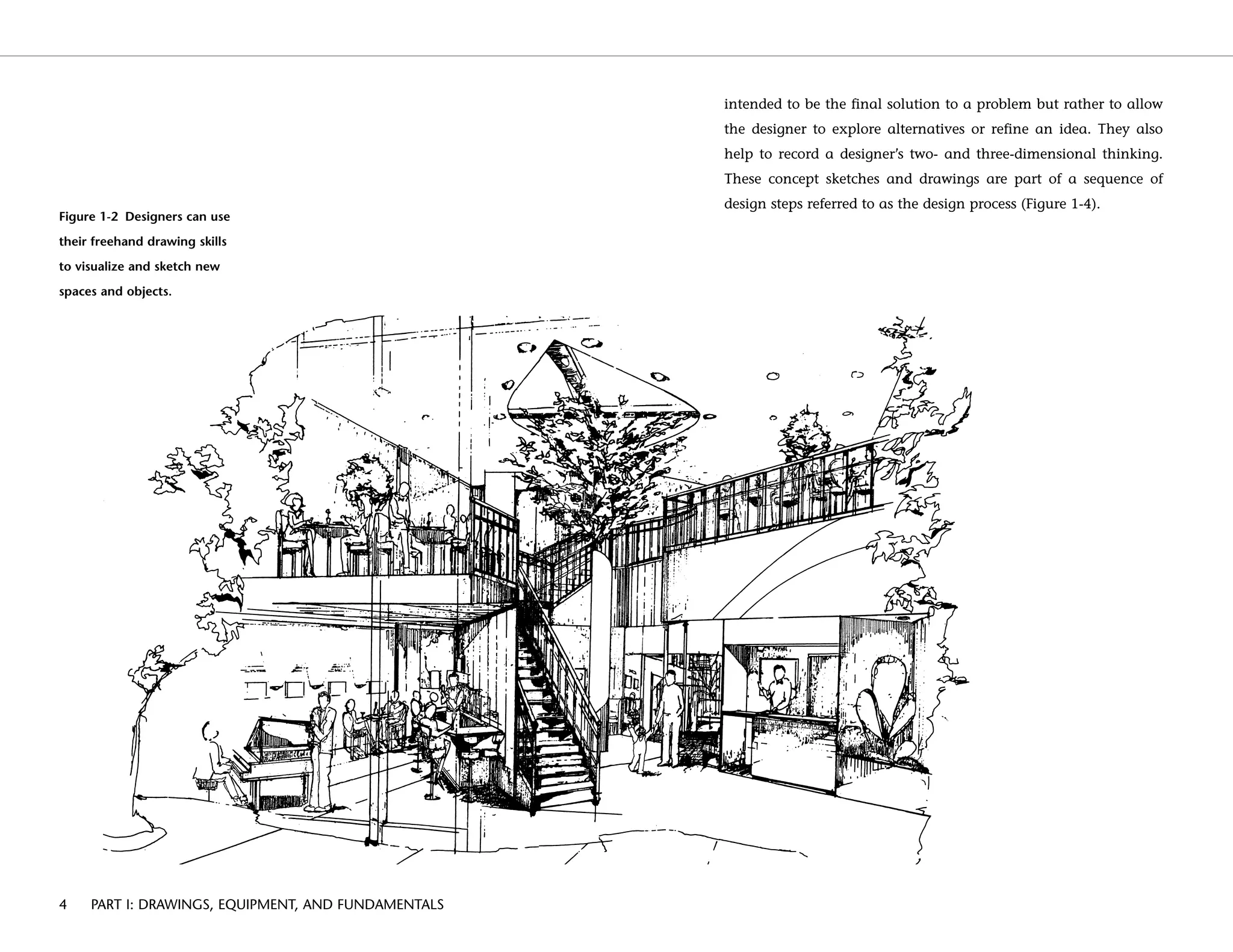
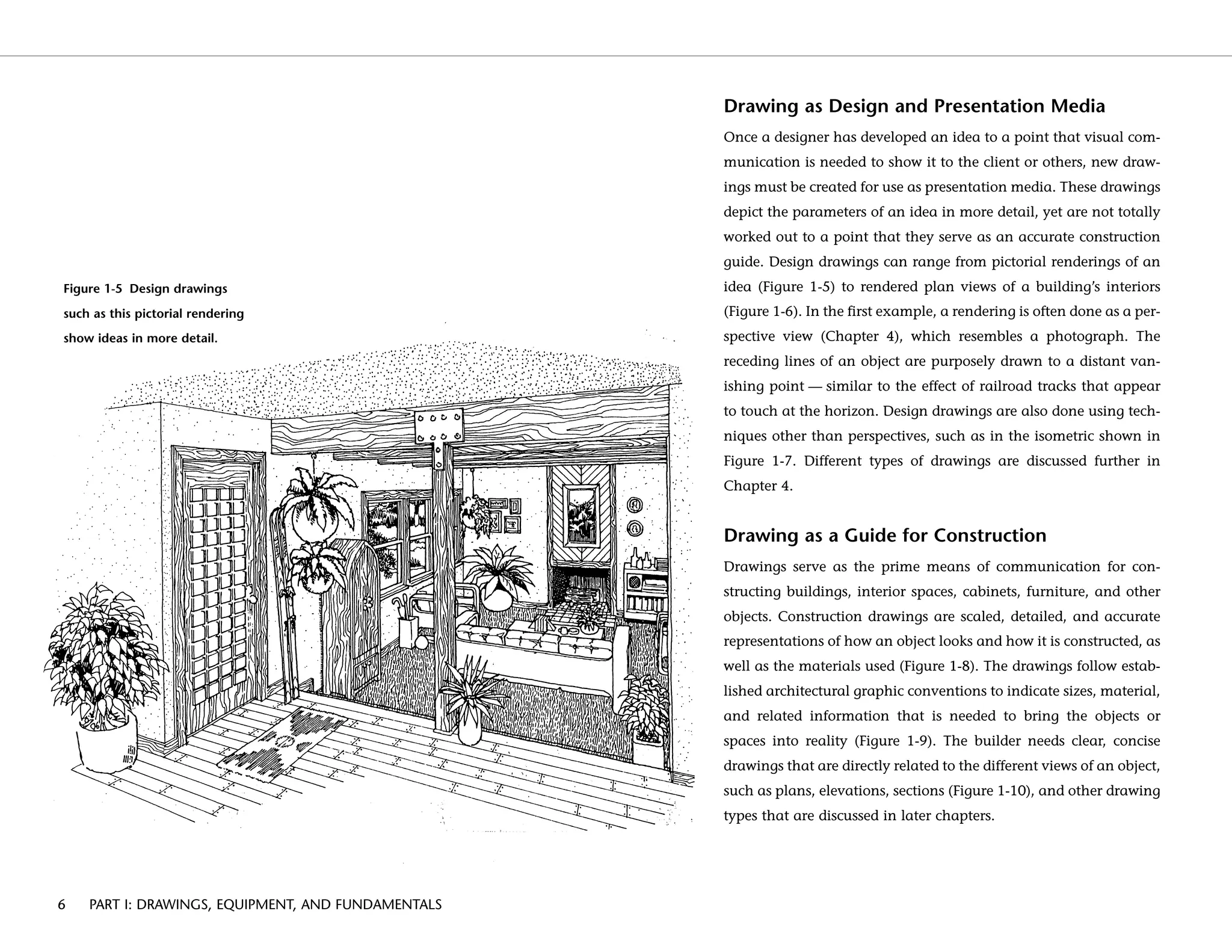
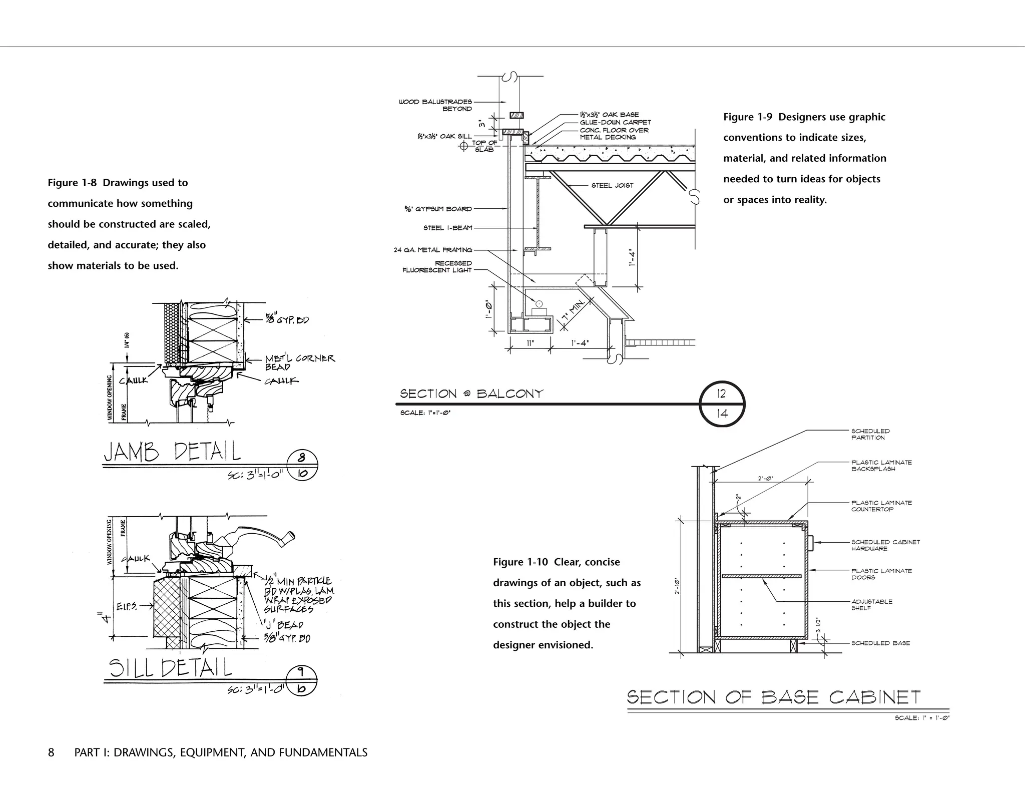
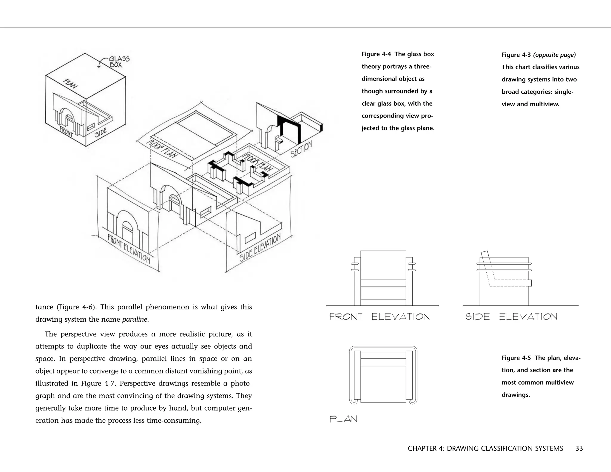
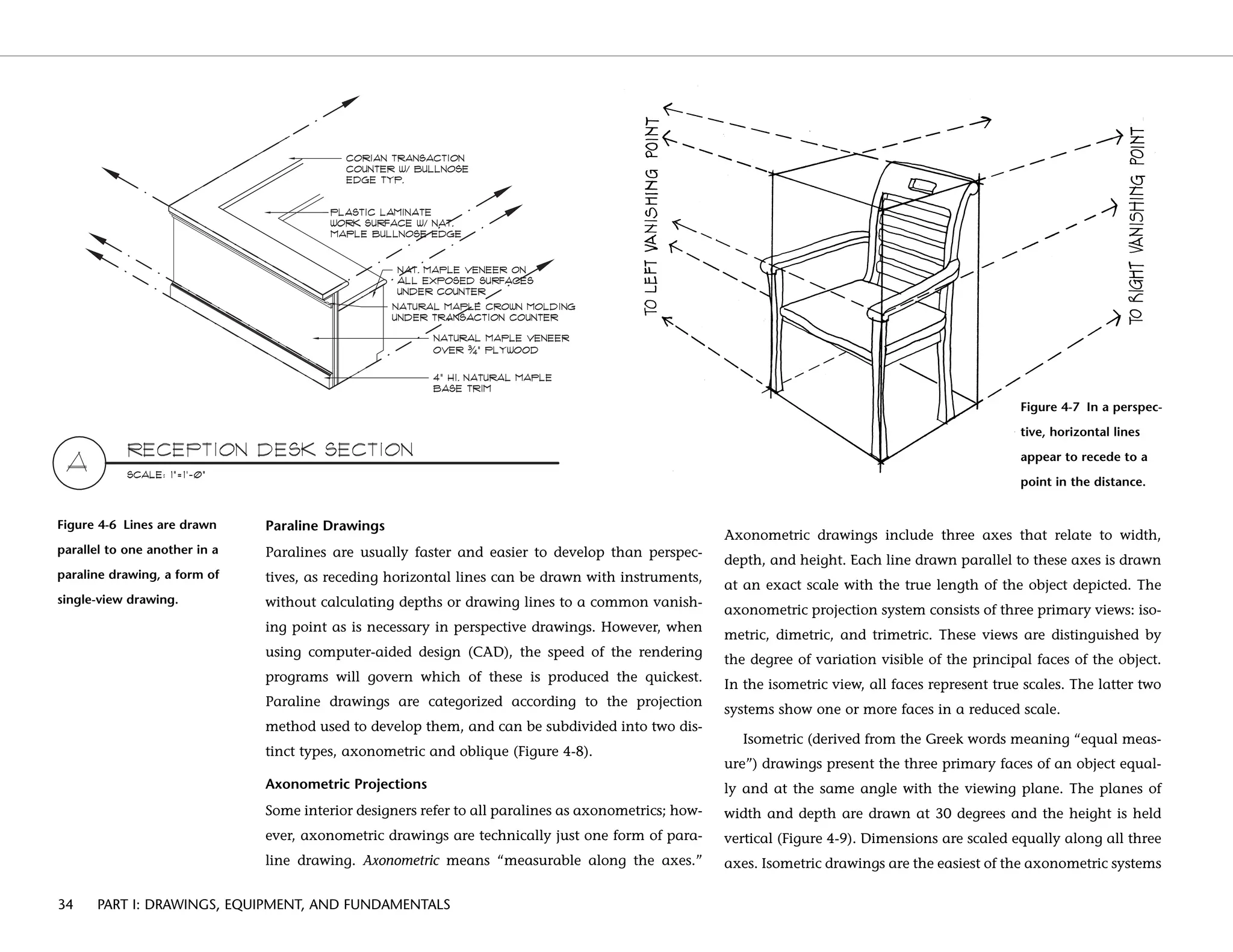
SlideShare a Scribd company logo
1 of 259
Download to read offline
CONSTRUCTION DRAWINGS
AND DETAILS FOR INTERIORS:
BASIC SKILLS
W. OTIE KILMER
ROSEMARY KILMER
John Wiley & Sons, Inc.
00.kilmer.fm 1/14/03 5:22 PM Page iii
00.kilmer.fm 1/14/03 5:22 PM Page ii
Construction Drawings
and Details for Interiors
00.kilmer.fm 1/14/03 5:22 PM Page i
00.kilmer.fm 1/14/03 5:22 PM Page ii
CONSTRUCTION DRAWINGS
AND DETAILS FOR INTERIORS:
BASIC SKILLS
W. OTIE KILMER
ROSEMARY KILMER
John Wiley & Sons, Inc.
00.kilmer.fm 1/14/03 5:22 PM Page iii
Dedicated to Courtney and Jeff Johnston, for their help and encouragement in writing this book.
This book is printed on acid-free paper. ∞
Copyright © 2003 by John Wiley & Sons, Inc. All rights reserved.
Published simultaneously in Canada
No part of this publication may be reproduced, stored in a retrieval system, or transmitted
in any form or by any means, electronic, mechanical, photocopying, recording, scanning,
or otherwise, except as permitted under Section 107 or 108 of the 1976 United States
Copyright Act, without either the prior written permission of the Publisher, or authorization
through payment of the appropriate per-copy fee to the Copyright Clearance Center, Inc.,
222 Rosewood Drive, Danvers, MA 01923, (978) 750-8400, fax (978) 750-4470, or on the
web at www.copyright.com. Requests to the Publisher for permission should be addressed to
the Permissions Department, John Wiley & Sons, Inc., 111 River Street, Hoboken, NJ 07030,
(201) 748-6011, fax (201) 748-6008, e-mail: permcoordinator@wiley.com.
Limit of Liability/Disclaimer of Warranty: While the Publisher and author have used their
best efforts in preparing this book, they make no representations or warranties with respect
to the accuracy or completeness of the contents of this book and specifically disclaim any
implied warranties of merchantability or fitness for a particular purpose. No warranty may
be created or extended by sales representatives or written sales materials. The advice and
strategies contained herein may not be suitable for your situation. You should consult with
a professional where appropriate. Neither the Publisher nor author shall be liable for any
loss of profit or any other commercial damages, including but not limited to special, incidental,
consequential, or other damages.
For general information on our other products and services or for technical support, please
contact our Customer Care Department within the United States at (800) 762-2974, outside
the United States at (317) 572-3993 or fax (317) 572-4002.
Wiley also publishes its books in a variety of electronic formats. Some content that appears
in print may not be available in electronic books. For more information about Wiley products,
visit our web site at www.wiley.com.
ISBN 0-471-10953-3
Printed in the United States of America.
10 9 8 7 6 5 4 3 2 1
00.kilmer.fm 1/14/03 5:22 PM Page iv
Preface vii
Acknowledgments ix
Part I — Drawing, Equipment, and Fundamentals 1
CHAPTER 1 DRAWING AS COMMUNICATION 3
Drawing for Idea Generation 3
Drawing as a Design and Presentation Media 6
Drawing as Guide for Construction 6
CHAPTER 2 DRAFTING EQUIPMENT AND ITS CARE 9
Drawing Tables and Surfaces 9
Drawing Papers and Plastic Films 10
Pencils, Leads, and Pens 11
Parallel Bar, T-Square, and Drafting Machines 14
Triangles, Templates, and Compasses 15
Scales 17
Erasers, Erasing Shields, and Brushes 18
Additional Equipment 20
CHAPTER 3 DRAWING AND DRAFTING FUNDAMENTALS 21
Starting the Drawing 22
Line Types 24
Drafting Standards, Abbreviations, and Symbols 26
Lettering 27
CHAPTER 4 DRAWING CLASSIFICATION SYSTEMS 31
Multiview Drawings 31
Single-view Drawings 32
Perspective Drawings 37
Part II — Contract Documents 47
CHAPTER 5 CONSTRUCTION DRAWINGS, SPECIFICATIONS,
AND CONTRACTS 49
Specifications 49
Contracts 51
Construction Drawings 52
Guidelines for Preparing Construction Drawings 59
Drawing Conventions and Representations 64
CHAPTER 6 FLOOR PLANS 77
Scale of Floor Plans 81
Drafting Standards 81
Dimensioning Floor Plans 93
Designation of Materials 96
Checklist for Floor Plans 97
CHAPTER 7 ELEVATIONS 99
Exterior Elevations 101
Interior Elevations 102
Scale of Interior Elevations 102
Drafting Standards for Interior Elevations 104
Designation of Materials 108
Dimensioning Elevations 110
Checklist for Interior Elevations 112
CHAPTER 8 SECTIONS 113
Types of Section Drawings 115
Drafting Standards 117
Building Sections 117
v
v
Contents
00.kilmer.fm 1/14/03 5:22 PM Page v
Sections of Interior Spaces 118
Wall Sections 119
Detail and Object Sections 121
Checklist for Section Drawings 122
CHAPTER 9 SPECIALTY DRAWINGS AND DETAILS 123
Purpose of Specialty Drawings 123
Stairs and Ramps 123
Millwork 129
Cabinetry 132
Fireplaces 136
CHAPTER 10 SCHEDULES 141
Door Schedules 144
Checklist for Door Schedules 148
Window Schedules 149
Checklist for Window Schedules 150
Finish Schedules 151
Checklist for Finish Schedules 152
Other Schedules 152
CHAPTER 11 FINISH PLANS 153
Scale of Finish Plans 156
Drafting Standards for Finish Plans 156
Designation of Materials in Finish Plans 157
Dimensioning Finish Plans 159
Checklist for Finish Plans 159
CHAPTER 12 FURNITURE INSTALLATION PLANS 161
Scale of Furniture Installation Plans 165
Drafting Standards for Furniture Installation Plans 165
Dimensioning Furniture Installation Plans 168
Designation of Materials 168
Checklist for Furniture Installation Plans 170
CHAPTER 13 FURNISHINGS AND EQUIPMENT PLANS 171
Scale of Drawings 175
Drafting Standards 175
Designation of Materials 177
Dimensioning of Furnishings and Equipment Plans 178
Checklist for Furnishings and Equipment Plans 178
CHAPTER 14 REFLECTED CEILING AND ELECTRICAL PLANS 181
Reflected Ceiling Plans 182
Electrical Plans 195
CHAPTER 15 MECHANICAL AND PLUMBING PLANS 201
Mechanical (HVAC) Plans 202
Plumbing Plans 207
Drafting Standards for Plumbing Drawings 210
CHAPTER 16 REPRODUCTION METHODS AND COMPUTERS 213
Reproductions of Drawings 214
Using Computers for Design, Communication, and Drafting 216
Appendix A MasterFormat™ Level Two Numbers and Titles 219
Appendix B Section Format Outline 225
Appendix C Sample ADA Guidelines 227
Appendix D Abbreviations for Construction Drawings 231
Glossary 233
Index 239
vi CONTENTS
00.kilmer.fm 1/14/03 5:22 PM Page vi
vii
vii
The design process for architectural interiors involves a series of
phases, each of which may call for drawings. At the outset, these
may include programming, schematic, preliminary, and design
development drawings. Such presentation drawings are created to
convey program elements, spatial relationships, materials, color
schemes, furnishings, and equipment, as necessary to set the design
concept for an interior. Construction drawings are then produced
that follow the design intent developed through these earlier draw-
ings. Construction drawings, also known as working drawings, are
graphic representations that communicate how to construct,
remodel, or install a project. These drawings also include related
information, such as room designations, door, window, and fixture
locations; dimensions; materials; and other details.
Construction drawings involve considerable time and attention
to detail. In many professional design firms, over 50 percent of a
project fee (payment from the client to the designer) might be allo-
cated to preparing construction drawings and the related specifica-
tions. This attests to the importance of construction drawings in the
overall process of designing and constructing environments.
Interior designers are taking an increasing role in coordinating
interior projects and for producing construction drawings. Interior
design and construction requires some unique types of drawing not
commonly addressed in textbooks or curricula. It is to speak to this
need that this book was created—as a handbook on preparing con-
struction drawings solely for the field of interior design.
The book has been designed for two groups of users: students in
interior design schools and interns in the offices that design interi-
ors; and professional interior designers and architecturs who need
a basic, yet comprehensive set of standards and techniques. For
students or interns, these pages are best used with an instructor or
mentor who can present the published materials, but augment
them with supplemental information and other exercises.
Computer-aided drawing (CAD) and computer-aided drawing
and drafting (CADD) are tools that have become integral to interi-
or design. This book thus provides a general introduction to using
the computer. It briefly discusses electronically storing and retriev-
ing documents for current and future projects. Many elements of a
current project can be copied and easily modified for future appli-
cation in other projects. In this manner, designers can build a
design database. Today, images, drawings and other information
are sent electronically to clients, consultants, suppliers, builders,
and other professionals. This is a far leap ahead of such past meth-
ods as copying and mailing or sending telephonic facsimile.
Working electronically has changed many of the ways designers
communicate their work, and is continually evolving.
However, this is not a textbook on how to draft with the com-
puter, or on the use of specific drafting software. Computer hard-
ware and software are constantly being upgraded and improved.
For this reason, this book focuses on how to incorporate a generic
CAD approach into the construction drawing process. Examples
are presented throughout the book of both electronic and hand-
drawn creations. Although many designers use CAD heavily in
their work, a significant number do not fully use it for all aspects
of the drawing process, or at all. Well-executed hand drawings can
still be effective design exploration and communication tools, and
sometimes they are even works of art.
Preface
00.kilmer.fm 1/14/03 5:22 PM Page vii
viii PREFACE
This book is organized in two parts. Part 1 (Chapters 1 through
4) first discusses graphic language as a communication tool in
design and architecture. Chapters 2 and 3 present equipment
needs and basic drafting principles for the beginning student.
Chapter 4 presents the drawing classification systems and how
they are used for idea generation and communication.
Part 2 (Chapters 5 throuth 16) detail the construction docu-
ment process. Overall concepts and organization are discussed,
as are specific examples. Chapter 16 discusses the use of com-
puters and the various systems for reproducing construction
drawings.
Examples used in the book include both residential and com-
mercial interiors. However, more emphasis is placed on commer-
cial projects, as these installations usually require more in-depth
detailing, coordination, and often multiple drawings/sheets due to
the larger spaces and number of building trades required. The illus-
trations represent high standards and can serve as guides for
design: linework, lettering, notation, and dimensioning that stu-
dents can aspire to in their own work. In addition to the authors’
drawings, examples are included from practicing professionals.
Drawings and details of interiors are included from a variety of
geographical areas—as design ideas, material, environmental fac-
tors, and accepted standards vary throughout the world. Projects
are also shown in relation to their compliance with the American
Disabilities Act and other code requirements. Dimensions are often
indicated in feet and inches, with metric equivalents for Canadian
and international applications.
A glossary and appendices are included listing commonly used
terms, graphic standards, and other information related to the
preparation of construction drawings for interiors.
00.kilmer.fm 1/14/03 5:22 PM Page viii
ix
Acknowledgments
The authors wish to express their sincere thanks to the following peo-
ple, who helped in the development and preparation of this book.
We are deeply grateful to the dedicated staff at John Wiley & Sons.
Without their guidance, assistance, and dedicated work, this project
would have never become a reality. Among these individuals the
authors are particularly indebted to Amanda Miller, Associate
Publisher. Her support, understanding, and perseverance to com-
plete this project are very much appreciated. Also, we wish to thank
Paul Drougas, Acquisitions Editor, for his help in the development
and final preparation of this project. To David Sassian, Associate
Managing Editor, for his diligence in editing and attending to the
many details that turned the manuscript into a finished book.
Special appreciation is expressed to the professionals and organ-
izations that provided us with illustrations and permissions to use
their materials to make this book a truly visual experience. We are
especially thankful to The Construction Specifications Institute,
American Society of Interior Designers, Hillenbrand Mitsch Design,
KJG Architecture, Inc., KraftMaid Cabinetry, Océ-USA, Inc., and
Hewlett-Packard Company. Every effort has been made to correctly
supply the proper credit information.
We are grateful to a number of interior design educators
throughout the country for their in-depth reviews, criticism, and
helpful suggestions as to the needs of students and instructors in
interior design.
Finally, we would like to express our deep appreciation to
Courtney and Jeff Johnston for their tireless help with the illustra-
tions and for their suggestions, based on their professional experi-
ence, as to contemporary standards and practices. Special thanks
also to Lisa Kilmer, for assistance and encouragement in the early
stages of this project.
00.kilmer.fm 1/14/03 5:22 PM Page ix
00.kilmer.fm 1/14/03 5:22 PM Page x
Part I
Drawings, Equipment,
and Fundamentals
1
01.kilmer 1/14/03 5:28 PM Page 1
01.kilmer 1/14/03 5:28 PM Page 2
3
Figure 1-1 Sketching existing
objects and spaces helps
designers develop their
freehand drawing skills.
1
DRAWING AS
COMMUNICATION
Ideas and plans are formed in the interior designer’s mind, but to be
transformed into reality, they have to be communicated to others.
Although a designer may have a great idea, it must be effectively
communicated or it will remain just an idea and never move
beyond conception. Interior designers and other professionals in the
building industry use drawings as the primary means of developing
and sharing their ideas. Interior designers and architects do a lot of
sketching and drawing. They develop their skills in freehand draw-
ing by sketching existing objects and spaces in the environment
(Figure 1-1). These same skills of observation and sketching are then
used in visualizing designs for new spaces and objects (Figure 1-2).
This process of brain, eye, and hand coordination is an intrinsic
part of design. Architectural drawings can be grouped into three
basic types: drawing as idea generation, drawing as a design and
presentation medium, and drawing as a guide for the construction
process. There are distinct differences between each of these types,
yet they all contain some common drawing tools, techniques, stan-
dards, and graphic language.
Drawing for Idea Generation
Idea generation assists the designer in working through and visu-
alizing the solution to a problem. Designers use many different
types of drawings to generate and bring to reality their creative
ideas. These drawings can be in the form of quick freehand
sketches illustrating different kinds of views (Figure 1-3). Many
times these types of drawings are not shown to clients but are used
solely to help designers shape their ideas. The drawings are not
01.kilmer 1/14/03 5:28 PM Page 3
intended to be the final solution to a problem but rather to allow
the designer to explore alternatives or refine an idea. They also
help to record a designer’s two- and three-dimensional thinking.
These concept sketches and drawings are part of a sequence of
design steps referred to as the design process (Figure 1-4).
4 PART I: DRAWINGS, EQUIPMENT, AND FUNDAMENTALS
Figure 1-2 Designers can use
their freehand drawing skills
to visualize and sketch new
spaces and objects.
01.kilmer 1/14/03 5:29 PM Page 4
Figure 1-3 Quick freehand
sketches such as this floor
plan can be used as a first
step in turning designers’
creative ideas into reality.
CHAPTER 1: DRAWING AS COMMUNICATION 5
Figure 1-4 Concept sketches
and drawings are part of a
sequence of design steps
known as the design process.
01.kilmer 1/14/03 5:29 PM Page 5
Drawing as Design and Presentation Media
Once a designer has developed an idea to a point that visual com-
munication is needed to show it to the client or others, new draw-
ings must be created for use as presentation media. These drawings
depict the parameters of an idea in more detail, yet are not totally
worked out to a point that they serve as an accurate construction
guide. Design drawings can range from pictorial renderings of an
idea (Figure 1-5) to rendered plan views of a building’s interiors
(Figure 1-6). In the first example, a rendering is often done as a per-
spective view (Chapter 4), which resembles a photograph. The
receding lines of an object are purposely drawn to a distant van-
ishing point — similar to the effect of railroad tracks that appear
to touch at the horizon. Design drawings are also done using tech-
niques other than perspectives, such as in the isometric shown in
Figure 1-7. Different types of drawings are discussed further in
Chapter 4.
Drawing as a Guide for Construction
Drawings serve as the prime means of communication for con-
structing buildings, interior spaces, cabinets, furniture, and other
objects. Construction drawings are scaled, detailed, and accurate
representations of how an object looks and how it is constructed, as
well as the materials used (Figure 1-8). The drawings follow estab-
lished architectural graphic conventions to indicate sizes, material,
and related information that is needed to bring the objects or
spaces into reality (Figure 1-9). The builder needs clear, concise
drawings that are directly related to the different views of an object,
such as plans, elevations, sections (Figure 1-10), and other drawing
types that are discussed in later chapters.
6 PART I: DRAWINGS, EQUIPMENT, AND FUNDAMENTALS
Figure 1-5 Design drawings
such as this pictorial rendering
show ideas in more detail.
01.kilmer 1/14/03 5:29 PM Page 6
CHAPTER 1: DRAWING AS COMMUNICATION 7
Figure 1-6 Design drawings can
also take the form of plan views.
Figure 1-7 Design drawings can
rely on a variety of techniques.
Pictured here is an isometric
drawing.
01.kilmer 1/14/03 5:29 PM Page 7
8 PART I: DRAWINGS, EQUIPMENT, AND FUNDAMENTALS
Figure 1-8 Drawings used to
communicate how something
should be constructed are scaled,
detailed, and accurate; they also
show materials to be used.
Figure 1-9 Designers use graphic
conventions to indicate sizes,
material, and related information
needed to turn ideas for objects
or spaces into reality.
Figure 1-10 Clear, concise
drawings of an object, such as
this section, help a builder to
construct the object the
designer envisioned.
01.kilmer 1/14/03 5:29 PM Page 8
9
2
DRAFTING EQUIPMENT
AND ITS CARE
To do any job accurately and expediently, a designer must have
the proper tools. Tools are important in all work — whether it be
surgery or carpentry, designing or drafting. Quality tools and
equipment will also make drawing and drafting more enjoyable.
Investing in good equipment for designing and drafting can bene-
fit both students and professionals.
The advent of computer-aided design and drafting, commonly
referred to as CAD, has reduced the need for much of the basic
equipment described in the following pages. However, many stu-
dents and professionals still prefer to draw manually in some situ-
ations, such as sketching initial design concepts or construction
details. To this end, basic manual equipment and techniques are
described in the next few chapters.
A designer or draftsperson need not buy every piece of new
equipment or software available. However, one should buy a new
product if it will improve one’s work, both in quality and efficien-
cy. Manufacturers often produce a range of models of varying
quality. One can decide which model will produce the best effects
in relation to the purchase price — sometimes not the top-of-the-
line model. One should purchase tools and equipment of good
quality, as they are an investment that will pay off throughout
one’s career.
Drawing Tables and Surfaces
To produce quality drawings for interior design projects, it is neces-
sary to establish a dedicated workplace. Designs can be drawn
manually on a drawing board set on a tabletop surface, on a
handmade drafting table, or on a ready-made drafting table. Or
they can be drawn using computer drafting hardware and software
that augments a drawing board or replaces it totally. In this chap-
ter, commonly used manual drafting tables, equipment and tools
are discussed. Computer drawing and drafting are discussed in
more detail in Chapter 16.
For interior designers, a fairly large layout and drawing surface
is needed most of the time. It is vital to have a drawing surface that
will hold large presentation boards and standard sheets up to 24 x
36 inches (731 x 914 mm). Even larger sheets may be necessary for
perspective drawings and full-size furniture drawings. A drawing
board or table approximately 30 x 50 inches (.762 x 1.27 m) should
be obtained if possible. This will allow adequate space around the
actual drawing sheet to place and maneuver the drawing tools and
materials.
Ready-made drafting tables are manufactured in a wide variety
of shapes, sizes, materials, and prices (Figure 2-1). Some styles have
an adjustable top and rest on four legs. Other models have a sin-
gle or double pedestal base with a top that can be raised or lowered
according to the chair or stool height. This enables drafters to sit in
a chair with a comfortable back and thus to work with less fatigue.
The newer models also allow the top to tilt at various angles for
comfort. This allows the drafter to work whether sitting or stand-
ing. Space-saving folding tables are also produced, although they
are not generally as sturdy as the fixed models.
02.kilmer 2/2/03 12:26 PM Page 9
10 PART I: DRAWINGS, EQUIPMENT, AND FUNDAMENTALS
Figure 2-1 A variety of pre-
manufactured drafting tables
are available to designers.
They range from very basic,
with few options for adjust-
ment, to quite sophisticated,
with electronic controls.
Manufactured tables have drawing surfaces that range in size
from 30 x 48 inches (762 x 1.21 mm) to 30 x 60 inches (.762 x 1.52
m) and are usually made of wood or hardboard over a cellular
core. However, a wood drawing surface can become scored and
grooved over time, which affects the drawing quality of the surface.
It is best to cover the bare wood top with a protective finish such as
plastic melamine or a vinyl drawing-board cover that gives a bit of
resiliency and is easy to keep clean. The latter covering is often pro-
duced with an off-white and a colored side. Which side to leave
faceup is left to the individual.
Drawing-board and table surfaces do not have to be manufac-
tured, as a self-made surface can also be satisfactory and less
expensive. For example, a hollow-core, flush door can be support-
ed on blocks or handmade legs made of 2x4 lumber with metal
brackets. However, the height and angle that suits individual work
habits must first be determined, as this type of drawing area will be
fixed and not adjustable.
Drawing Papers and Plastic Film
Interior design drawings can be produced on paper or plastic film.
The quality of paper or film will help determine the quality of
linework. A variety of papers and plastic films are manufactured
today in many standard sheet sizes and rolls. The choice of which
to use is dependent upon the designer’s overall intent, office stan-
dards, and the intended method selected for making a copy from
the original.
Papers
Drafting papers are made in a large variety of types, based on sta-
bility, translucency, permanence, strength, and cost. There are two
basic categories: opaque and translucent. Opaque papers are
02.kilmer 2/2/03 12:26 PM Page 10
CHAPTER 2: DRAFTING EQUIPMENT AND ITS CARE 11
thicker than translucent ones and cannot be reproduced through
methods such as the diazo printing process (see Chapter 16 for
reproduction methods). Therefore, they are not suitable for con-
struction drawings that are to be copied in this manner. They are
more suitable for plotting directly from a computer (in single sheets
or rolls) and for concept and presentation drawings, as they are
available in a variety of colors ranging from white to gray, cream,
green, and blue. Some opaque papers are made smooth on one
side and rough on the other. The smooth side is more appropriate
for inking and the rough side for pencil drawings. Most papers will
accept ink or pencil. However, the quality of their application and
possible bleed-through varies according to the composition of the
paper and its thickness.
Translucent papers, such as tracing paper and vellum, are used
for drawings that are to be reproduced through the diazo process.
However, they can also be reproduced photostatically. Tracing
paper is generally a natural, untreated translucent paper. It is used
primarily for exploratory ideas and sketches. It is commonly sold
in inexpensive rolls (in white or yellow shades) and called “trac-
ing,” “trash,” “flimsy,” or “bum wad.” It is fairly strong and
durable, but not as transparent as vellums, and will not produce
line work as crisp and clear as vellums.
Vellum is a translucent tracing paper that is treated to improve
strength, surface texture, and transparency. Vellums also have a
high rag content that gives them strength so they can withstand
erasing. Vellum is sold in rolls or standard sheet sizes and can be
used for hand or computer drafting. Standard sheet sizes for archi-
tectural drawings are shown in Table 2-1.
Plastic Films
Plastic drafting films are tough, translucent, polyester sheets. Their
common thickness ranges from 0.002, 0.003, 0.004, 0.005, and
0.0075 inch to 0.05, 0.08, 0.10, 0.14, and 0.19 mm. The sheets may
be frosted on one side and smooth on the other or frosted on both
sides. Drawing is done on the frosted side, which accepts pencil or
pen more readily than the smooth side.
Special plasticized lead pencils were at one time commonly used
with plastic films, but they are not as prevalent as they once were.
These are discussed in the paragraph under leads in the next sec-
tion. Special ink is also available for drawing on plastic film. Both
pencil and ink lines are very clear and crisp on plastic films and
produce very clear, clean prints. Plastic films are sold in rolls and
standard sheet sizes. The films are generally more expensive than
tracing paper or vellum and used primarily for permanent records
or tough originals for multiple reproductions.
Pencils, Leads, and Pens
Pencils are one of the most basic and primary drawing tools of the
professional designer. There are three basic types of pencils avail-
able to a designer for producing quality drawings (Figure 2-2). The
selection is a matter of preference and the particular level of per-
formance needed by the user.
Wood-Cased Pencil
The oldest manufactured pencil is of wood with a lead encased
inside. It is seldom used for repetitive work in today’s office, yet is
still a reliable tool for occasional use for convenience and when
Table 2-1 Standard Paper Sizes
Architectural Drawing Metric
Type Size (in.) Type Size (mm)
A 81
/2 x 11 A4 210 x 297
B 11 x 17 A3 297 x 420
C 17 x 22 A2 420 x 594
D 24 x 36 A1 594 x 841
E 36 x 48 A0 841 x 1189
02.kilmer 2/2/03 12:26 PM Page 11
pencil line control is needed. To expose the lead, the wood shell is
cut away by a draftsman’s pencil sharpener. However, the sharpen-
er only cuts the wood and does not touch the lead. To “point” the
lead, the designer can use a lead pointer, which forms the lead into
a conical point. If a wedge point is desired, rubbing the lead on
sandpaper can form it. Wood-cased pencils come in a variety of dif-
ferent lead weights, ranging from 9H (extremely hard) to 6B
(extremely soft). These leads are explained later in this chapter.
Traditional Leadholder
This type of mechanical pencil is made of metal or plastic, with
special individual leads inserted in a permanent holder. Different
lead weights may be inserted to produce a variety of sharp line
weights. Pencil leads are graded from 9H (hard) to F (firm) to 6B
(black). Beginners should sharpen the point frequently for a clear,
sharp line until they develop the ability to rotate the pencil while
drawing to wear the point more evenly. The lead is sharpened by
rubbing and rotating on sandpaper, on regular paper, or in a spe-
cial mechanical lead pointer. When using sandpaper to sharpen
the lead, it should be slanted at a low angle to achieve a good taper
and point.
Fine-Line Mechanical Pencil
This type of mechanical pencil does not require sharpening and is
loaded with multiple leads of the same diameter and hardness. The
pencil generally is made to hold 0.3, 0.5, 0.7, or 0.9 mm diameter
lead. The size of the lead determines the line width. This type of
pencil is also generally rotated while drawing, and capable of pro-
ducing consistently sharp, clean lines. Like the traditional lead-
holder, the mechanical pencil offers the convenience of a steady
supply of lead, as the leads are inserted in the bottom of the hold-
er and pushed out the tip by pressing a button on the end of the
12 PART I: DRAWINGS, EQUIPMENT, AND FUNDAMENTALS
Figure 2-2 The three types of
pencils available for designers
are the wood-cased pencil, the
traditional leadholder, and the
fine-line mechanical pencil.
Table 2-2 Pencil-lead Weights*
9H
8H
7H Hard pencil leads are used for drawings, light layouts,
6H and drawings requiring a high degree of accuracy.
5H
4H
3H
2H
H These leads are used for sketching, architectural
F line work, lettering and general purposes.
HB
B
2B
3B
Soft leads are used for sketching,
4B
rendering, and graphical accents.
5B
6B
*The gradations can vary with different brands and types of drawing media.
When in doubt, try a sample or test first.
02.kilmer 2/2/03 12:26 PM Page 12
CHAPTER 2: DRAFTING EQUIPMENT AND ITS CARE 13
Figure 2-3 Technical fountain
pens and ink refill.
pencil. It is the most widely used pencil in today’s schools and
offices for sketching, note-taking, and even drafting.
Leads
A variety of leads are available for both wood and mechanical
pencils. Leads used on tracing paper and drafting paper are com-
posed of graphite. Leads range in grades from 9H (extremely hard)
to 6B (extremely soft). (See Table 2-2.) The softer the lead, the dark-
er the image or line it will produce. For most drafting work, where
clean, crisp lines are necessary, H and 2H leads are used. For
sketching, softer leads are better, such as F and HB. Very soft leads,
such as the B grades, are best for pencil renderings and shadowing
work. For light, preliminary layout work, 3H and 4H leads are best.
Generally, the more “tooth” or roughness a paper has, the hard-
er the lead should be. Also, the harder the drawing surface, the
softer the lead will feel. If you are in high humidity conditions, the
apparent hardness of the lead tends to increase.
As noted before, there are also special plastic-leaded pencils
available for drawing on plastic drafting film. These plastic leads
are available in five grades of hardness, ranging from E1 (soft) to E5
(super hard). They are water-resistant and bond well to the plastic
film. A vinyl eraser is also available for use with these special leads.
Pens
Some designers prefer ink and use a technical fountain pen (Figure
2-3), as it is capable of precise line width. It can be used for both
freehand and drafted ink drawings. As with drafting pencils, pens
are available in a variety of forms and price ranges. However, most
technical drawing pens consist of a tubular point, which has an
ink-flow-regulating wire inside it. The size of the tubular point is
what determines the finished width. Standard widths of ink lines
are measured according to a line-width code, such as .30/00, which
means the line width is .30 mm or the American standard size of
00. Metric widths range from .13 to 2.0 mm, while the American
standard widths range from 000000 to 6. These sizes correspond to
line-width designations developed by the American National
Standards Institute (ANSI) and are coordinated with metric sizes.
For a starter pen set, a good range of point sizes would be 3x0 (.25
mm), 2x0 (.3 mm), 1 (.45 mm), and 3 (.80 mm). Technical pens
that produce the same line widths are also available with felt tips.
These are less costly, however their felt tips tend to wear out faster
than the metal tips.
An advantage to using ink, especially on plastic drafting film, is
that it will last several years longer than pencil, will not smudge,
and will produce excellent reproductions. When using technical
pens, remember to keep points screwed in securely to prevent the
ink from clogging. Always replace the cap firmly after each use to
02.kilmer 2/2/03 12:26 PM Page 13
14 PART I: DRAWINGS, EQUIPMENT, AND FUNDAMENTALS
keep the ink from drying, and store the pens with their points up
when not in use.
Use a good waterproof black drawing ink. Good nonclogging
ink that is specially made for use in fountain and technical pens is
the best choice.
Parallel Bar, T-Square, and Drafting Machines
It is extremely important to make sure lines on design drawings
and construction drawings are exactly straight and, when
required, parallel. To make sure lines are straight in a horizontal,
vertical, and angular direction, there are several tools available.
The most common of these instruments are the T-square and par-
allel bar (Figure 2-4). A device called a drafting machine (Figure
2-5) is also sometimes used.
T-Square
A T-square consists of a straightedge with a head set at right angles
that can be set flush against the edge of a drawing board or table.
The head is generally very sturdy and immovable. T-squares come
in different lengths to coordinate with various drawing board sizes.
The most common lengths are 36 and 42 inches (.91 and 1.06 m).
They are available with opaque or transparent edges, the latter
making it easier to see through to existing lines when spacing by
eye. To use a T-square, one holds it with one hand (usually the left)
at the head so it can be moved into position and held in place
while a line is drawn along the straightedge with the other hand.
The T-square is inexpensive and portable, which makes it conven-
ient for students. However, in modern practice the T-square has
been replaced by the parallel bar and the drafting machine, as
they do not require a constant hand to steady the head.
Figure 2-4 The T-square and
the parallel bar are used to
create straight lines, whether
they are horizontal or vertical.
Figure 2-5 An arm-track drafting
machine can produce horizontal,
vertical, and angular lines.
02.kilmer 2/2/03 12:26 PM Page 14
CHAPTER 2: DRAFTING EQUIPMENT AND ITS CARE 15
Parallel Bar
A parallel bar is attached by cleats and pulleys to a particular
drawing surface. The bar moves up and down on thin wire that
moves runs over pulleys inside the bar. When properly installed,
the bar can be moved up and down the drawing board and always
be parallel with the top of it. Parallel bars are available in a vari-
ety of lengths to fit different drawing board sizes. The parallel bar
is easy to use. It permits the drafter to draw long horizontal lines
and serves as a base for the placement of triangles and other instru-
ments for precision drawing.
Drafting Machines
A drafting machine is a combination of several conventional draft-
ing tools. It is fixed to the drawing board and consists of vertical
and horizontal blades that serve as scales for linear measurement,
eliminating the need for a triangle and T-square for drawing verti-
cal and horizontal lines. There is also a scale in angular degrees on
the head that replaces the protractor.
There are two basic types of drafting machines — the arm type
and the track type. The arm type has two arms that pivot in the cen-
ter with a head at the end of the lower arm — which is clamped to
the top edge of the drafting table. The drafter moves the head up
and down and right and left. The head and the scales on it remain
parallel to their original setting. The track type has a horizontal
track mounted to the top edge of the drafting table with a vertical
track attached to it that slides left and right. The head with the
scales on it is fastened to the vertical track and slides up and down.
Drafting machines are available for right- or left-handed people.
Right-handed people hold the head in place with the left hand.
Left-handed people hold the head in their right hand with the
scales facing the opposite direction.
The scales on drafting machines can be set at angles by releas-
ing a lock, pressing a release button and turning the head.
Frequently used angles such as 30, 45, and 60 degrees have positive
set points. Scales are available in several lengths, in either archi-
tectural or metric measurements. They are also available in either
plastic or aluminum finishes.
Triangles, Templates, and Compasses
A variety of other drawing tools are available for constructing ver-
tical or inclined lines as well as circles, curvilinear shapes not based
on fixed-radius circular forms, and other special shapes such as
representations of furniture, plumbing fixtures, and other interior
equipment and furnishings.
Triangles
A triangle is a three-sided instrument used with the T-square or
parallel straightedge for drawing vertical and angular lines (Figure
2-6). The most common are 45-degree and 30/60-degree triangles,
each named for the angles they form. A range of sizes is available,
with a size of 8 or 10 inches (203 x 254 mm) being in the middle of
the range. Their size is based on the length of the longest side of the
right angle. It is best to begin with these; then larger and smaller
sizes can be added as needed. For example, small triangles, such as
4 inches (101 mm), are useful for hand-lettering and crosshatching
small areas.
Adjustable triangles can be set for any angle from 0 to 45
degrees. The adjustable triangle is convenient for situations requir-
ing a variety of sloping lines, such as for stairs or slanted ceilings.
Some triangles are available with recessed edges for use when
inking. This keeps the edge up off of the paper so the ink doesn’t
run under the triangle and become smeared. Triangles are avail-
02.kilmer 2/2/03 12:26 PM Page 15
16 PART I: DRAWINGS, EQUIPMENT, AND FUNDAMENTALS
able in a clear (nonyellowing) or colored plastic. They are scratch-
resistant and generally have good edge retention. They should not
be used as a cutting edge as they are easy to nick, and they must
be used and stored carefully.
Templates
Templates are prepunched patterns representing various shapes
commonly used in interior design and architectural plans (Figure
2-7). Templates help to speed up the drafting process and aid in the
production of accurate drawings. There are a variety of templates
available, some of which are used regularly, while others are need-
ed for special purposes only. There are templates that are used to
draw circles, squares, windows, doors, electrical symbols, plumbing
fixtures, furnishings, and hundreds of other features.
The circle template is a very basic and highly useful timesaving
device for drawing accurate circles of various sizes as well as curves
that are parts of circles. Circles range in size from 1
⁄16 inch (1.58 mm)
up to 2 inches (50.8 mm) in diameter. Ellipse templates come in
similar sizes, but since ellipses vary from near flat to near circular,
a series of templates may be needed for each size. However, a single
guide with the most commonly used proportions is available.
French curved templates are excellent tools for drawing irregu-
lar curved lines that are not part of a circle or ellipse. These guides
consist of at least a dozen traditional forms that can help a design-
er draw almost any flowing curve needed. There are also flexible
drawing curves available that can be bent as needed to fit an irreg-
ular curved line. They can hold the shape as the line is drawn, then
straightened out after use.
Other useful templates include forms for both residential and
commercial furniture, as well as plumbing fixtures, retail fixtures,
and lighting and electrical symbols. Lettering templates are also
Figure 2-6 Triangles are also
used to create straight lines
when drawing. When used
with a parallel bar or T-square,
angular and vertical lines can
be drawn. Shown on the left is
a fixed 30-60 triangle; on the
right is an adjustable triangle.
Figure 2-7 Templates are used
to speed up the drafting
process by tracing the punched
shapes directly onto a drawing.
Templates come in a variety of
patterns and scales.
02.kilmer 2/2/03 12:26 PM Page 16
CHAPTER 2: DRAFTING EQUIPMENT AND ITS CARE 17
available, but even though they may be convenient they often
appear stiff and are not frequently used in design offices. Lettering
templates are best used for very large letters and numbers that may
be difficult to form freehand.
Compass
A compass is an inverted V-shaped instrument used for drawing
circles and arcs (Figure 2-8). It has a pin at the end of one leg and
a leadholder at the end of the other. A special device will allow
technical pen points to be used with the compass. The best way to
use a compass is to mark a centerpoint and the radius desired on
a piece of paper and adjust the compass to that measurement by
setting the pin on the center point and setting the pencil or pen
point on the radius mark. Hold the compass firmly at the top, lean-
ing it a little in the direction the circle will be drawn, then rotate it.
Generally, rotating it in a clockwise direction is easier. Press hard
enough to get the desired line weight. Be careful to match line
weights of circles and arcs to the rest of the drawing.
Scales
Measuring tools are extremely important to the interior designer,
because a designer’s plans, elevations, sections, and details must
always be drawn with all their dimensions at the same fractional
part of their real (full-size) dimensions. Architectural and interior
design line work generally represents objects that are much larger
than the drawing paper; therefore, a proportional measuring sys-
tem must be used. This scale of the drawing is always stated on the
drawing. When a drawing is drawn to scale, this means that all
dimensions on the drawing are related to the real object, or space,
by an appropriate selected scale ratio. For example, when drawing
at a scale of 1
⁄8" = 1'0", each 1
⁄8" increment in the drawing represents
a foot in the full-size object.
Figure 2-8 Compasses are used to
draw circles and arcs; this illustra-
tion shows a compass with a lead
point, and the attachment used
when drawing with ink.
The term scale also refers to the physical measuring device used
by designers to accurately reduce linear distances to their correct
scaled lengths. Scales are special rulers that can be used for meas-
uring in a variety of units and that enable the designer to draw an
object larger than, smaller than, or the same size as the real (full-
size) object. Scales are calibrated in inches or millimeters much
like a regular ruler. They are available in either a flat or a trian-
gular shape (Figure 2-9). Triangular scales are very popular
because as many as four scales can be printed on each face.
Generally, a triangular scale has as many as 11 different scales on
it. The shape also makes them convenient to pick up and use. Flat
scales generally have either a two-bevel or four-bevel edge,
02.kilmer 2/2/03 12:27 PM Page 17
18 PART I: DRAWINGS, EQUIPMENT, AND FUNDAMENTALS
When using the architect’s scale, begin at the 0 point, then
count off the number of feet, using the major subdivisions that are
marked along the length of the scale. The scaled inches are locat-
ed on the other side of the 0 point.
The engineer’s scale is a full divided scale, as it has the inches
marked along its edge, which are then divided into decimal parts
of an inch. The engineer’s scale generally contains 6 different divi-
sions/scales. These divisions are indicated as 10, 20, 30, 40, 50,
and 60. These numbers mean “parts to an inch.” For example, the
40 scale means 1 inch = 40 feet. As there are 40 subdivisions with-
in an inch, each mark represents 1 foot. This scale can also be
used to represent larger units such as 400 or 4,000 feet per inch.
Engineer’s scales are generally used for drawing large-scale site
plans and maps.
Metric scales are used when drawing architectural and interior
plans in metric units. The millimeter is the basic unit of the metric
scale. Metric scales are based on ratios, such as 1:50, which means
1 mm on the scale represents 50 mm. Typical ratios are 1:10, 1:25,
1:50, 1:100, 1:200, and 1:500. To enlarge a drawing, scales are
available in 2:1 and 5:1 ratios. Since metric scales are based on the
metric system, using the base 10, it is possible to use single-ratio
scales for other ratios. For example, a 1:1 scale with 1-mm mark-
ings could also be used to represent 1 mm, 10 mm, 100 mm, or
1000 mm. A 1:2 metric scale could be used for 1 mm to represent
20 mm, 200 mm, and so forth.
Erasers, Erasing Shields, and Brushes
To be able to erase errors and correct drawings is very important to
the interior designer. Erasability is one of the key advantages of
using a pencil or pen for drawings. Erasers, erasing shields, and
brushes are convenient tools of almost equal importance.
Figure 2-9 Scales are special
rulers designed to measure in a
variety of units, enabling objects
to be drawn at various sizes.
Scales are available in English
and metric units, and in various
shapes and sizes. A scale should
never be used as a straightedge.
depending on the number of scales they carry. Good-quality scales
must have sharply defined graduations that are close to the edge
for accurate measurements. Scales are not meant to be a straight-
edge, and should never be used as a pencil or inking guide when
drawing a straight line.
There are several different types of scales, but the interior
designer will mainly use the architect’s scale, engineer’s scale, and
metric scale.
The architect’s scale is the one most frequently used by an inte-
rior designer. It is used for laying out accurate design and con-
struction drawings in feet and inches. Architectural scales general-
ly contain 11 different divisions, where each major division repre-
sents 1 foot. The major divisions are indicated as 3
⁄32, 1
⁄16, 1
⁄8, 3
⁄16, 1
⁄4,
3
⁄8, 1
⁄2, 3
⁄4, 1, 11
⁄2, and 3. Each one of these divisions represents one
foot on the scale. For example, the 1
⁄4 scale means 1
⁄4 of an inch on
the scale represents 1 foot.
02.kilmer 2/2/03 12:27 PM Page 18
CHAPTER 2: DRAFTING EQUIPMENT AND ITS CARE 19
Erasers
A wide variety of both rubber and synthetic erasers are available.
A good eraser must be capable of completely removing pencil or
ink lines without leaving smudge marks or roughing the surface of
the paper. For vellum drafting paper, soft rubber erasers should
generally be used. There are also special erasers designed to
remove ink. However, be careful, as these erasers are too abrasive
for some drawing surfaces. Some ink erasers claim to have a sol-
vent incorporated into them for better erasing of ink. Erasers are
available in either block form or stick form inserted into a holder
much like a leadholder (Figure 2-10). Vinyl and other plastic
erasers are designed for use on plastic drafting film.
Electric erasers are extremely useful when a great amount of
erasing is necessary. Electric erasers are small handheld tools that
hold long round lengths of eraser that are rotated when turned on.
The cordless variety is the most convenient (Figure 2-11).
Figure 2-10 Erasers come in
various shapes and sizes, and
different kinds can erase pen-
cil or ink. Shown are a
mechanical eraser-holder, a
plastic block eraser in a sleeve,
and a basic block eraser.
Figure 2-11 An electric eras-
er can be very handy when
erasing large areas of a
drawing and is especially
convenient when cordless.
02.kilmer 2/2/03 12:27 PM Page 19
20 PART I: DRAWINGS, EQUIPMENT, AND FUNDAMENTALS
Figure 2-12 An eraser shield
allows for precise erasing, as it
shields the parts of the draw-
ing that are to remain. The
prepunched holes allow the
designer to erase only those
lines needing to be erased.
Erasing Shield
A small metal or plastic card with prepunched holes and slots is
used to erase precise areas of a drawing, as shown in Figure 2-12.
The prepunched holes come in a variety of sizes and shapes, allow-
ing the designer to erase small details and control the erasure up
to a particular point. It is also helpful for protecting the drawing
surface while using an electric eraser. Although the transparency of
a plastic shield can be convenient, a metal shield generally lasts
longer.
Brushes
A dusting brush is useful for keeping drafting surfaces clean and
free of debris (Figure 2-13). Erasure crumbs are sometimes left on a
drawing surface to help prevent smudges, but if they become too
abundant they can cause lines to skip, so it is helpful to brush the
drawing surface often.
Additional Equipment
A number of additional tools may assist the designer. For example,
full-circular (360 degrees) and half-circular (180 degrees) protrac-
tors aid in the layout and measuring of angles on a drawing. They
are manufactured in a variety of sizes in both metal and plastic
(Figure 2-14).
Figure 2-13 Dusting brushes
can be used to clean an area
in preparation for drawing,
or to clean erasure crumbs
from a drawing in process.
Figure 2-14 Protractors aid
designers in laying out and
measuring angles. They come in
a variety of sizes and materials.
02.kilmer 2/2/03 12:27 PM Page 20
21
3
DRAWING AND DRAFTING
FUNDAMENTALS
Drawing and drafting are forms of visual language that use lines,
pictorial images, and symbols to convey specific meanings. Like
spoken language, written language, and body language, this visu-
al language has its own unique applications. In the design field,
drawing, also called sketching or idea generation, is used as a tech-
nique for developing and communicating ideas. Preliminary
sketches are used to initiate and explore basic concepts, as illus-
trated in Figure 3-1. These can be presented to others as is, or
refined into presentation drawings that are developed to scale and
rendered in more detail. Drawing is thus a means of communica-
tion used by designers to effectively convey ideas and converse with
one another about how to turn them into reality.
Drafting is a particular type of drawing that conveys specific
information about something’s size, composition, assembly, and
other exacting characteristics. Drafting is usually a means to an
end; that is, it serves as a guide on how to make something. For
these reasons, drafting is founded on a number of basic premises
and rules. A draftsperson’s specialized drawings, generally referred
to as working drawings or construction drawings, help the design-
er to develop ideas and communicate to the builder the exact
parameters of their design concepts — assisting in the construction
of a physical interior environment or building (Figure 3-2).
Construction drawings require a great deal of effort to draw, as
they must be clear, concise, and accurate, with high-quality lines
and legible dimensions and notes.
Figure 3-1 Sketching is a
form of visual communica-
tion used to initiate and
explore basic concepts.
This illustration shows vari-
ous sketches all relating to
each other, helping to visu-
alize a concept.
03.kilmer 2/2/03 12:33 PM Page 21
22 PART I: DRAWINGS, EQUIPMENT, AND FUNDAMENTALS
To draw and draft at a professional level, one must learn some
basic skills and techniques. This chapter will introduce the basics
needed to produce quality and easily readable drawings and so
effectively communicate with others.
Starting the Drawing
Drawings are executed on a paper or plastic sheet that is placed on
the drawing board or surface. It is usually held in place on the
drawing surface with drafting tape placed at the four corners, as
illustrated in Figure 3-3. The opposite corners are pulled and taped
alternately to stretch and flatten the sheet. When one is finished
with the drawing or needs to remove it for a short period of time,
the tape is carefully removed and discarded. The sheet can then be
stored flat or rolled for convenience. There is a tendency for begin-
ners to roll original drawings and prints with the original line work
or printed side on the inside, probably in an effort to protect the
line work. However, the preferred way to roll a drawing is to do it
with the printed information on the outside. In this way, as the
drawing is unrolled, it will tend to curl away from the viewer and
toward the surface it is placed on (Figure 3-4). This keeps the draw-
ing from constantly curling up toward the viewer. This technique is
also effective for multiple copies stapled together in sets.
Drawings are produced on a variety of surfaces with varying
types of media, as discussed in Chapter 2. One of the first steps in
composing a properly scaled drawing is to select the best size and
format for the surface. To do this effectively, a number of variables
must be taken into account. These include the complexity and
scale of the drawing, the reproduction technique selected, and the
viewing conditions the reader will be under.
Figure 3-2 A precise
drawing illustrating how
stairs and landings should
be constructed.
03.kilmer 2/2/03 12:33 PM Page 22
CHAPTER 3: DRAWING AND DRAFTING FUNDAMENTALS 23
Drawing Page Layout
Original drawings, particularly those done in pencil, need to be
kept clean to provide for the clearest reproduction. Smudged draw-
ings will often produce smudged prints that are difficult and time-
consuming to read. Graphite from pencils is the greatest threat to
drawing cleanliness. Sliding hands, elbows, and equipment over
pencil lines will blur them and produce an undesirable patina over
the entire drawing surface. The same is true with ink drawings,
whether they are done by hand or computer. Time must be allowed
for the ink to dry. Equipment should be lifted and placed over draw-
ings, not slid from one area to another. Regular washing of hands
and equipment will also help prevent smudging of line work.
In manual drawing, one should start with very light lines and
darken those as needed for the final drawing (Figure 3-5). On the
computer, “pen” settings determine the value or thickness of a line
(Figure 3-6). There is no preliminary stage of drawing with light
lines. In manual drawings, it is good practice to start drawing at
the upper portion of the sheet and progress toward the bottom of
the paper. In this way, most drawings will not be disturbed as you
move the equipment and hands down the sheet. Of course, com-
puter drawing allows one to begin almost anywhere on the sheet,
compose the drawings, and print out the results in one clean plot.
The machine doesn’t worry about top to bottom or left to right —
it follows the composition set by the designer.
Figure 3-4 Rolling drawings
with the printed information
on the inside causes them to
curl and hide the drawing from
the viewer when unrolled and
laid flat. Rolling them with the
information on the outside
allows the viewer to look at
the drawings without having
the paper curl up and hide
the drawing.
Figure 3-3 The drawing
paper is held in place on the
drawing surface with small
pieces of drafting tape.
03.kilmer 2/2/03 12:33 PM Page 23
Line Types
Lines are drawn to describe objects, hidden conditions, and impor-
tant relationships between components and space. A line drawn
on a surface has both direction and weight. The weight of a line
refers to its thickness and intensity; a line can also be continuous
or dashed. The direction can be straight, curved, diagonal, or a
combination of these. In drafting, continuous lines of various
weights are used to represent objects and major elements such as
structural walls and columns. Dotted lines are usually used to
denote objects hidden from view. However, they can also be used to
24 PART I: DRAWINGS, EQUIPMENT, AND FUNDAMENTALS
Figure 3-5 When draw-
ing manually, light lines
should be used to lay out
an image or text. Final
lines can then be dark-
ened according to the
desired line hierarchy.
Figure 3-6 When using
the computer to create a
drawing, various “pen”
weights/widths can be
assigned to lines for the
desired line hierarchy.
03.kilmer 2/2/03 12:33 PM Page 24
CHAPTER 3: DRAWING AND DRAFTING FUNDAMENTALS 25
Figure 3-7 These are common
line types used in drawings to
describe objects, hidden condi-
tions, and important relation-
ships between components and
space.
denote other things, such as a wheelchair turning radius or ceiling
height changes on a floor plan. The following are the most com-
monly used line types. Examples are shown in Figure 3-7.
• Cutting lines: show major slices in a building or object.
• Object lines: show major outlines of building elements or
objects.
• Hidden lines: indicate areas or objects not visible on the
surface, or objects hidden behind others. They are also
used to show objects above the cutting plane of a floor
plan, such as wall cabinets, beams, arches, etc.
• Centerlines: locate the symmetrical center of objects such
as windows, doors, beams, and walls.
• Dimension lines and extension lines: indicate the physical
dimensions of objects. Dimensions are placed directly
above the dimension line or inserted within it.
• Leaders: line extending from text and ending with an
arrow, pointing to an object or place.
• Break lines: indicate where an object or area is not drawn
in its entirety.
• Layout lines: are used in the preliminary blocking out of
components and for lettering guidelines.
Line Weights and Their Uses
Line weight refers to the blackness (intensity) and width of a line
on the drawing surface. In general, heavy (dark) lines are used to
represent cutting planes and contours (or outer boundaries) of an
object. In a floor-plan view, it is often the walls that are drawn with
the darkest lines in order to define the spaces (Figure 3-8). These
lines appear to be the closest to the viewer and are perceived as
major elements. Medium and lighter lines appear to be farther
away from the viewer and are used for secondary emphasis.
Drawings for interior design projects generally use three line
widths: thick (dark), medium, and thin (light). Thick lines are gen-
erally twice as wide as thin lines, usually 1
⁄32 inch or about 0.8 mm
wide. Thin lines are approximately 1
⁄64 inch or 0.4 mm wide.
Medium lines fall between these two extremes. In pencil drawings,
each type can be further broken down, depending on the variety of
lead and level of pressure. With the variety of mechanical pencils
on the market today, it is easy to control line widths. As discussed in
Chapter 2, fine-line mechanical pencils are available in a 0.3, 0.5,
0.7, or 0.9 mm lead. By switching to different pencils, the drafter
can vary line weight easily.
03.kilmer 2/2/03 12:33 PM Page 25
26 PART I: DRAWINGS, EQUIPMENT, AND FUNDAMENTALS
Thick, Dark Lines
Thick, dark lines are used for major sections (Figure 3-9), details,
borderlines, and cutting plane lines. A thick, intense line can rep-
resent the walls on a floor plan or structural members, such as fire-
places or stairways, the outline of a ceiling on a reflected ceiling
plan, or the outline of a building on a site plan. Thick, intense lines
are also used to emphasize an object or element.
Medium Lines
Medium-weight lines are used for hidden objects and are usually
drawn dashed or dotted. They are also used for outlining the
planes of objects and for centerlines, as well as for furniture and
equipment.
Thin, Light Lines
Thin, light lines are generally used as guidelines, drawn to help
line up certain details or to help with lettering height. These lines
should be barely visible and should disappear when a print or copy
is made. Lines that are a little darker are used for dimension and
extension lines, leaders, door swings, and break lines.
Drafting Standards, Abbreviations, and Symbols
A designer’s drawings are used to communicate specific informa-
tion to many other individuals, such as owners, architects, engi-
neers, and builders. To do this effectively, a number of drafting
standards, abbreviations, and symbols have been developed over
time that have become uniformly acceptable in the building indus-
try. Although an office may use variations of the standard con-
ventions presented here, most follow some version of these con-
ventions. Many construction terms are abbreviated to save draw-
ing space and eliminate the need for detailed drawings or notes.
For example, a W8x31 is a standard steel beam whose exact phys-
Figure 3-8 In a floor plan,
the walls are often drawn
darkest to define the
spaces. The viewer tends
to see these lines first, and
thus they are perceived as
major elements.
Figure 3-9 Dark, thick
lines are commonly used
in building sections to
denote where a plane
is cut.
03.kilmer 2/2/03 12:33 PM Page 26
CHAPTER 3: DRAWING AND DRAFTING FUNDAMENTALS 27
ical and structural properties are detailed out in industrywide steel
manuals. Another example is the commonly used term “above fin-
ished floor,” which is abbreviated as A.F.F. and used in floor plans
and electrical plans. The most commonly used abbreviations are
discussed in Chapter 5 and shown in the Appendix.
Symbols are used to represent objects that cannot be depicted
accurately or would take too much time to draw. For example, the
details of a window in plan or a wall electrical outlet are impracti-
cal to draw with clarity at such a small scale. These are represent-
ed in the plan by an acceptable symbol that is cross-referenced to
a legend or note to more clearly define the object (Figure 3-10).
Various components such as sinks, doors, windows, and electrical
devices are drawn as symbols. These will be discussed in more
depth in later chapters.
Sections cut through the building and materials are depicted
using common symbols to represent their elements rather than
drawing them as they might appear. For example, a section
through a piece of plywood is shown schematically instead of
drawn realistically to show the intricate layers of cross-grained
wood veneers and glue. Symbols for materials are often drawn dif-
ferently in a plan view and section view. In most cases, an attempt
is made to portray as closely as possible what the actual cross-sec-
tion would look like (Figure 3-11). Again, typical symbols for archi-
tectural materials are discussed more in Chapter 5 and shown in
the Appendix.
Lettering
Lettering is used to communicate ideas and to describe elements
that cannot be effectively explained with just drawings. In some
cases, words are actually a clearer and more economical way to
Figure 3-10 In this illustra-
tion, an electrical plan is
shown with various electri-
cal symbols, and the leg-
end above describes what
each symbol represents.
03.kilmer 2/2/03 12:33 PM Page 27
28 PART I: DRAWINGS, EQUIPMENT, AND FUNDAMENTALS
communicate. To ensure written words are quickly understood, a
universal lettering style is commonly employed by designers and
architects (Figure 3-12). This style, based on the Roman alphabet,
generally consists of all capital letters for ease of reading. Although
most designers employ a universal-looking style, individual styles
do develop and are often recognized and associated with the per-
son who uses them. However, stylistic differences must not be so
extreme that letters and words become difficult or time-consuming
to read. The intent of architectural lettering is to communicate
quickly and clearly. Many firms attempt to unify lettering among
their personnel by adopting an office standard.
Today, computer software quickly produces lettering in many
styles that appear to be hand-lettered or typed (Figure 3-13). Some
of these are so realistic it is difficult to tell whether they really are
done by hand or by computer. However, this does not mean that
there is not a need for a student or designer to learn and produce
good hand-lettering. The ability to hand-letter is still much alive
and needed. We still need to have effective handwriting when com-
municating with clients, builders, and many others in the field. A
designer’s lettering style can also be a kind of professional trade-
mark that distinguishes him or her as a creative individual.
Basic Guidelines for Lettering
Good lettering is made by consistency. This includes height of let-
ters, style, and spacing between letters. To maintain consistency in
height, hand-lettering is always done using two or more horizontal
guidelines. To maintain consistency between lines of lettering, the
distance between these lines should be measured with a scale or
other device. Then, when the draftsperson gains more proficiency,
this distance can be fairly accurately “eyeballed” in. The two lines
serve as the upper and lower limits of the letters. A third line can
serve as a consistent guide for parts of letters or even lower-case let-
Figure 3-11 Materials that are cut through in sec-
tion are depicted graphically. An attempt is made to
represent the material, but in general it is drawn
simplistically, since drawing all the intricate details
would be too time-consuming.
03.kilmer 2/2/03 12:33 PM Page 28
CHAPTER 3: DRAWING AND DRAFTING FUNDAMENTALS 29
ters (Figure 3-14). The draftsperson must endeavor to keep the let-
ters within the top and bottom lines, and not let parts of the letters
extend beyond these. In most cases, the guidelines are produced
with such a light line that they are left in and not erased. In pen-
and-ink drawing, these lines might be laid out in nonreproducible
blue pencil lines.
Most designers prefer vertical strokes in lettering, although
slanted characters are often faster to produce. Letters should be
produced with bold strokes, not drawn with a series of sketched and
ragged lines. There should be a distinct start and stop to each line
stroke within a letter. Shapes and proportions of lettering should be
consistent throughout a drawing (Figure 3-15). Close attention
Figure 3-12 In order to make
words and letters in drawings
quickly and easily understood,
a universal style of lettering is
used that is usually done in all
capital letters.
Figure 3-13 Lettering on the
computer can be done in many
styles, even one that simulates
hand-lettering.
03.kilmer 2/2/03 12:33 PM Page 29
30 PART I: DRAWINGS, EQUIPMENT, AND FUNDAMENTALS
should be given to the width of a letter, as well as the proportional
spaces between letters. This spacing is very important, as it gives
words good visual formation and clarifies their relationship to
other words. In general, spacing between letters in a word should
be made approximately equal in the beginning of the designer’s
career. However, this rule can be modified as the designer gains
confidence, as proportional spacing can vary a bit, depending on
the shapes of the letters.
One shortcut used for lettering by some designers is the aid of a
small triangle carried along the parallel bar (or other horizontal
device) and quickly brought into play for vertical strokes within a
letter. This technique produces a very consistent vertical lettering
style, but some designers see it as a crutch. If this technique is used,
it should be discontinued once the draftsperson gains the ability
and confidence to produce accurate vertical lines.
To effectively learn proper lettering, one should produce words
and numbers, not just individual letters. Practice by copying phras-
es from articles and books, or writing a story. This will give you bet-
ter skills in forming properly proportioned letters and spaces
between them.
Figure 3-14 Horizontal
guidelines can be used for
height consistency when
lettering. Two or three
guidelines can be used,
and these lines can remain
on the drawing if produced
lightly.
Figure 3-15 Lettering
should be consistent
throughout a drawing;
the shapes and propor-
tions should be similar.
03.kilmer 2/2/03 12:33 PM Page 30
31
4
DRAWING CLASSIFICATION
SYSTEMS
Design drawings enable the professional designer to visualize and
communicate the features of a three-dimensional object or interior
space. Then, detailed construction drawings are made to accurate-
ly describe what materials are to be used and how the object or
space is to be constructed. The design drawing can be a three-
dimensional pictorial sketch that shows what the object looks like
in reality (Figure 4-1), or a series of related yet different views of the
object, such as a plan or top view and an elevation, as illustrated
in Figure 4-2. The first approach, the single view, attempts to por-
tray the object as the eye would see it. The second approach, the
multiview, relies on the eye to view a series of images and the mind
to then put these views together into a whole. For example, a floor
plan shows width and length of objects within a space. An eleva-
tion view is then drawn to illustrate height, but no third dimension
or true depth is visually indicated. Figure 4-3 classifies the various
drawing systems according to these two broad categories. Many
computer software programs now can produce some very convinc-
ing single-view drawings from multiviews, then allow designers to
quickly flip back and forth between these two types of drawings.
Multiview Drawings
Multiview drawings can be visualized by what is commonly called
the glass box theory. In this process, a three-dimensional object is
imagined to be surrounded by a clear glass box (Figure 4-4). If the
viewer looks along the perpendicular through any plane on the
glass box, the object can be imagined to be a flat, two-dimension-
al image on that particular glass pane. The object can be viewed
Figure 4-1 Design drawings
may consist of pictorial sketches
that show an object as the eye
might see it.
Figure 4-2 Different views of an
object help the eye understand
the object as a whole.
04.kilmer 1/14/03 10:30 PM Page 31
32 PART I: DRAWINGS, EQUIPMENT, AND FUNDAMENTALS
from above (called a plan view) or the side (called an elevation
view). In turn, if these images are drawn separately, the viewer
reverses the process and projects (by imagining) the multiviews
onto a whole three-dimensional object.
Orthographic Projections
The word orthographic refers to the projection system that is used to
derive multiview drawings based on the glass box model. Drawings
that appear on a surface are the view a person sees on the trans-
parent viewing plane that is positioned perpendicular to the view-
er’s line of sight and the object. In the orthographic system, the
object is placed in a series of positions (plan or elevation) relative
to the viewing plane.
The most common types of orthographic drawings are the plan,
elevation, and section (Figure 4-5). However, no single one of these
drawings can communicate the actual configuration of a three-
dimensional object or space. They must be used together to accu-
rately depict spatial and solid elements. In fact, more complex
objects and spaces will require several more of each of these draw-
ings. Multiview drawings lack the pictorial effect of perspectives
(which are a type of single-view drawing), yet are more accurate for
conveying correctly scaled objects, interiors, and buildings.
Single-view Drawings
Single-view drawings attempt to picture an object or space as we
normally see it in reality with all three dimensions appearing
simultaneously. They present relationships of objects, space, and
materials in a realistic or photographic-looking manner. Single-
view drawings can be either paraline or perspective views. In par-
aline drawings, lines are drawn parallel to one another, and object
features retain this relationship as they appear to recede in the dis-
04.kilmer 1/14/03 10:30 PM Page 32
CHAPTER 4: DRAWING CLASSIFICATION SYSTEMS 33
tance (Figure 4-6). This parallel phenomenon is what gives this
drawing system the name paraline.
The perspective view produces a more realistic picture, as it
attempts to duplicate the way our eyes actually see objects and
space. In perspective drawing, parallel lines in space or on an
object appear to converge to a common distant vanishing point, as
illustrated in Figure 4-7. Perspective drawings resemble a photo-
graph and are the most convincing of the drawing systems. They
generally take more time to produce by hand, but computer gen-
eration has made the process less time-consuming.
Figure 4-4 The glass box
theory portrays a three-
dimensional object as
though surrounded by a
clear glass box, with the
corresponding view pro-
jected to the glass plane.
Figure 4-3 (opposite page)
This chart classifies various
drawing systems into two
broad categories: single-
view and multiview.
Figure 4-5 The plan, eleva-
tion, and section are the
most common multiview
drawings.
04.kilmer 1/14/03 10:31 PM Page 33
Paraline Drawings
Paralines are usually faster and easier to develop than perspec-
tives, as receding horizontal lines can be drawn with instruments,
without calculating depths or drawing lines to a common vanish-
ing point as is necessary in perspective drawings. However, when
using computer-aided design (CAD), the speed of the rendering
programs will govern which of these is produced the quickest.
Paraline drawings are categorized according to the projection
method used to develop them, and can be subdivided into two dis-
tinct types, axonometric and oblique (Figure 4-8).
Axonometric Projections
Some interior designers refer to all paralines as axonometrics; how-
ever, axonometric drawings are technically just one form of para-
line drawing. Axonometric means “measurable along the axes.”
34 PART I: DRAWINGS, EQUIPMENT, AND FUNDAMENTALS
Axonometric drawings include three axes that relate to width,
depth, and height. Each line drawn parallel to these axes is drawn
at an exact scale with the true length of the object depicted. The
axonometric projection system consists of three primary views: iso-
metric, dimetric, and trimetric. These views are distinguished by
the degree of variation visible of the principal faces of the object.
In the isometric view, all faces represent true scales. The latter two
systems show one or more faces in a reduced scale.
Isometric (derived from the Greek words meaning “equal meas-
ure”) drawings present the three primary faces of an object equal-
ly and at the same angle with the viewing plane. The planes of
width and depth are drawn at 30 degrees and the height is held
vertical (Figure 4-9). Dimensions are scaled equally along all three
axes. Isometric drawings are the easiest of the axonometric systems
Figure 4-7 In a perspec-
tive, horizontal lines
appear to recede to a
point in the distance.
Figure 4-6 Lines are drawn
parallel to one another in a
paraline drawing, a form of
single-view drawing.
04.kilmer 1/14/03 10:31 PM Page 34
CHAPTER 4: DRAWING CLASSIFICATION SYSTEMS 35
Figure 4-8 There are two types
of paraline drawings:
axonometric and oblique.
Figure 4-9 Isometric drawings
present the three primary
faces of an object equally and
at the same angle with the
viewing plane.
04.kilmer 1/14/03 10:31 PM Page 35
36 PART I: DRAWINGS, EQUIPMENT, AND FUNDAMENTALS
to construct, but the visual distortion caused by parallel lines not
appearing to converge to a distant vanishing point gives them a
distinctly pictorial effect. Computer software now allows the
designer to program in dimensions for width, height, and depth.
Then, isometric “wire frames” that show the construction lines can
be quickly generated on the screen, as illustrated in Figure 4-10.
Hidden or unwanted lines can also be easily turned off or removed
from the image.
In dimetric and trimetric drawings, all principal faces are not
held at equal angles to the picture plane (Figure 4-11). The dimet-
ric drawing makes two faces equally visible and shortens the third
face. The trimetric rotates an object so that all three faces are at dif-
ferent angles to the picture plane.
In both dimetric and trimetric drawings, the scale along one or
more of the principal faces is reduced proportionately to emphasize
or deemphasize a feature of the object. Both dimetric and trimetric
drawings are more time-consuming to construct than isometric
drawings, but have the advantage of presenting an object’s best
features and more closely resembling perspective drawings.
Oblique Projections
Oblique projections are popular among interior designers.
Although there are several types of oblique drawings, the plan
oblique and elevation oblique are the most commonly used. In
these drawings, the floor plan or elevation serves as the true face
on the picture plane, and parallel lines are projected vertically or
horizontally at an angle other than 90 degrees from this face. The
viewer’s lines of sight are parallel, but are not at right angles with
the viewing plane (Figure 4-12). Oblique drawings also have the
feature that one face of an object is always parallel to the viewing
plane and represented in true proportion, such as an elevation or
plan view. The parallel lines are sometimes reduced in scale (short-
Figure 4-10 Isometric drawings
are generally constructed as
“wire frames” showing the
construction lines.
Figure 4-12 In a plan oblique
drawing, the true plane can be
rotated at any angle, although
the 30-60 degree and 45-45
degree are most popular.
04.kilmer 1/14/03 10:31 PM Page 36
CHAPTER 4: DRAWING CLASSIFICATION SYSTEMS 37
ened) from true size to reduce the visual distortion. With the use of
specialized computer software, these views can be generated or
extruded from a plan or elevation view with the click of a mouse.
To produce a plan oblique, the true shaped plan can be rotated
to any angle, although the 30/60-degree and 45/45-degree are the
most popular. The advantage of the plan oblique is that the build-
ing’s floor plan can be used directly to generate this kind of draw-
ing. By contrast, isometrics are more time-consuming because of
the extra projections and dimensioning required. A floor plan or
elevation cannot be used directly to produce an isometric drawing.
Perspective Drawings
A perspective drawings is a type of single-view drawing that is
more realistic-looking than an oblique or axonometric drawing. In
a perspective drawing, objects appear to diminish in size as they
recede into the distance, and lines that are parallel in the actual
object appear to converge at some distant point on the horizon
(termed the vanishing point). Perspectives are used primarily as
presentation drawings to portray a finished object, building, or
interior space (Figure 4-13). Perspectives most closely duplicate
what our eye or a camera sees.
Perspectives have characteristics that distinguish them from
paraline and orthographic drawings. These characteristics are:
• Convergence of parallel lines
• Diminution of size
• Foreshortening
• Overlapping of forms
These properties, as illustrated in Figure 4-14, help make per-
spectives very realistic compared to the other types of drawings.
Perspective drawings are broken into three basic categories accord-
Figure 4-11 In diametric and
trimetric drawings, all princi-
pal faces of an object are
not held at equal angles to
the picture plane.
04.kilmer 1/14/03 10:31 PM Page 37
38 PART I: DRAWINGS, EQUIPMENT, AND FUNDAMENTALS
Figure 4-13 Perspective draw-
ings are the most realistic-
looking and are often used
as presentation drawings.
04.kilmer 1/14/03 10:31 PM Page 38
CHAPTER 4: DRAWING CLASSIFICATION SYSTEMS 39
Figure 4-14 Perspective drawings
use four properties that make them
more realistic than paraline and
orthographic drawings.
04.kilmer 1/14/03 10:31 PM Page 39
40 PART I: DRAWINGS, EQUIPMENT, AND FUNDAMENTALS
ing to the number of vanishing points used to construct them
(Figure 4-15). To construct perspectives, an imaginary picture
plane is placed between the observer and the object (or interior) to
be drawn. If this plane can be placed parallel to one plane of an
object, parallel lines will appear to converge to only one point, pro-
ducing the one-point perspective, as shown in Figure 4-16. If the
picture plane is placed parallel to only one set of lines (the vertical
lines, for example), the results are termed a two-point perspective
(Figure 4-17). The parallel lines then appear to converge to two
vanishing points. A three-point perspective is produced when all
the lines or faces of an object are oblique (not parallel) to the pic-
ture plane. This method is not often used for interior spaces, but
rather for tall buildings. Each of these perspective types can be
hand-drawn in a number of different ways. A projection system
can be used to produce an individualistic drawing for a specific
object or space (Figure 4-18). Or a preconstructed perspective grid
can be made and overlay sheets placed over it to draw a perspec-
tive. One method for constructing a grid is shown in Figure 4-19.
Perspective grids can be drawn for each project, or preprinted grids
can be made with the lines already drawn in true perspective.
These grids can be generated by hand or computer, or one can pur-
chase preprinted grids.
One-Point Perspectives
Of the three types of perspective, the one-point is perhaps the eas-
iest to understand and construct. In one-point perspectives, reced-
ing lines or sides of an object appear to vanish to a single point on
the horizon. These types of perspectives are often used to produce
room interiors, either from an elevation (front view) or plan (top
view), depending on where the observer is standing (called the sta-
tion point), as illustrated in Figure 4-20. The setup for both of these
Figure 4-15 There are three
basic categories of perspective
drawings, depending on the
number of vanishing points.
04.kilmer 1/14/03 10:31 PM Page 40
CHAPTER 4: DRAWING CLASSIFICATION SYSTEMS 41
Figure 4-16 In a one-point per-
spective, the picture plane is
parallel to an object, and the
parallel lines will appear to con-
verge to only one point.
Figure 4-17 In a two-point per-
spective, the picture plane is
placed parallel to only one set
of lines (the vertical lines in this
example), and the parallel lines
appear to converge to two van-
ishing points.
04.kilmer 1/14/03 10:31 PM Page 41
42 PART I: DRAWINGS, EQUIPMENT, AND FUNDAMENTALS
Figure 4-18 In the hand-drawn method,
a plan projection system is used to pro-
duce an individualistic drawing for a
specific object or space.
Figure 4-20 The station point, shown
in this plan view, represents the point
from which the interior of the room
will be seen in perspective.
04.kilmer 1/14/03 10:31 PM Page 42
CHAPTER 4: DRAWING CLASSIFICATION SYSTEMS 43
Figure 4-19 An example of how to
draw a one-point perspective grid.
04.kilmer 1/14/03 10:31 PM Page 43
44 PART I: DRAWINGS, EQUIPMENT, AND FUNDAMENTALS
is exactly the same, the difference being whether the observer is
positioned above or at the horizon. The station point can also be
moved to the left or right to emphasize the particulars of the space.
Two-Point Perspective
The two-point perspective is one of the most widely used of the
three types, as it portrays the most realistic view for the observer
(Figure 4-21). By placing the object at unequal angles from the
right and left vanishing points (which corresponds to the viewer’s
position in the space), dynamic views can be produced. However, if
the viewer’s position is moved too far over to one side or the other,
distortions can occur in the final drawing. In most interior views,
the eye-level perspective is the preferred choice. Two-point perspec-
tives are more difficult to hand-draw than one-point perspectives,
as planes must be projected to two vanishing points, as illustrated
in Figure 4-22.
Three-Point Perspective
Three-point perspectives are generally drawn with the viewer at a
distance above the horizon (bird’s-eye view) or below the horizon
(worm’s-eye view). The three-point perspective is used mostly for
very tall buildings and is rarely used in interior spaces, unless they
are multistoried. Three-point perspectives are more complicated
than the former two types, as a third vanishing point is introduced,
which precludes all parallel lines.
Figure 4-21 The two-point perspec-
tive is used more often than the
one-point and three-point perspec-
tives, because it portrays a more
realistic view of an object or space.
04.kilmer 1/14/03 10:31 PM Page 44
CHAPTER 4: DRAWING CLASSIFICATION SYSTEMS 45
Figure 4-22 How to draw a two-
point perspective grid.
04.kilmer 1/14/03 10:31 PM Page 45
04.kilmer 1/14/03 10:31 PM Page 46
Part II
Contract Documents
47
05.kilmer 1/14/03 10:40 PM Page 47
05.kilmer 1/14/03 10:40 PM Page 48
49
5
CONSTRUCTION DRAWINGS,
SPECIFICATIONS, AND CONTRACTS
Specifications, contracts, and construction drawings are an inte-
gral part of what is referred to as the contract documents. These
documents form a guide for the various workers and suppliers to
follow in constructing the project. The construction drawings show
the location, size, and particulars of a structure to be built. The
specifications set the standards of the workmanship and materials
in writing. The drawings and specifications complement one
another and are used together. For example, the drawings show
the color and location of paint to be applied to a wall surface, but
do not tell how it is to be applied (sprayed, rolled, or brushed) and
the resulting quality of workmanship required. In this case, the
subsurface must first be prepared to receive the paint, adjacent
areas need to be protected from the painting, the minimum skills
of the painter must be specified, and the cleanup needed must be
called out. These particulars are all detailed in written specifica-
tions for the painting, and similar instructions are prepared for all
the other work to be carried out on the project.
Specifications
Specifications are written documents that clearly describe the
required materials, requirements for the execution of the work, and
workmanship expected. Generally, for small, simple projects the
written specifications may be placed directly in the drawings,
either typed on transparent adhesive film or in text form in CAD
on a separate drawing sheet. However, for most projects, the speci-
fications are included in a “job book” or “project manual” and
issued with the contract agreements and construction drawings as
the complete set of contract documents.
The job book can be a bound or loose-leaf manual and contains
the technical specifications. A project manual may include the
specifications as well as other documentation for the total project,
such as the contract(s), bidding requirements (if needed), and gen-
eral and supplementary conditions of the contract.
Specification Types
Specifications should complement the construction drawings, not
duplicate them. Their main purpose is to describe the type and
quality of materials and finishes; quality and method of construc-
tion and installation; acceptable testing methods; alternate provi-
sions; and warranties and their requirements. Specifications are
referred to as “closed” or “open” for bidding purposes. “Closed”
means no product can be used on the project other than what is
specified. Open specifications allow for the substitution of prod-
ucts specified, or for the contractor to suggest a number of prod-
ucts for the item that is specified or being bid on. There are four
main types of specifications: proprietary, descriptive, reference,
and performance.
Proprietary
Proprietary specifications, which are closed, call out a specific man-
ufacturer’s products by name, model or part number, and color or
finish, if applicable. Proprietary specifications are the most restric-
tive, as they give the interior designer complete control over what is
05.kilmer 1/14/03 10:40 PM Page 49
designer’s requirements rather than a trade name. However, refer-
ence specifications are generally based on standards that are set by
an established authority or testing facility, such as the American
Society for Testing and Materials (ASTM) or the American National
Standards Institute (ANSI).
These authorities provide minimum performance criteria for
various materials and products. Reference specifications are gener-
ally short, because only the standard must be stated, and they are
fairly easy to write. Chances for error are minimal, as industry
standards and generally recognized methods of building are being
used. However, the designer must be completely familiar with and
updated on the standard and how to write the appropriate specifi-
cation. Sometimes the standard includes more provisions than are
needed for a particular project.
Performance
Performance specifications describe the expected performance of
the item(s) being specified. This type of specification is also consid-
ered open, as no trade names are included. Any item that meets
the performance criteria can be used in the project. The means by
which the required results are met is not specified, but left up to the
contractor, subcontractor, or vendor. Performance specifications
are often used for custom components when the designer wants to
achieve a particular result that is not already manufactured. This
type of specification can be more difficult to write, because the
designer must know all the criteria expected as well as methods for
testing (if required). Also, there is a risk that the designer could lose
his or her original design concept along with control over the prod-
ucts used if it is not carefully written.
Organization of Specifications
The organization of written specifications has been standardized in
accordance with the building trades. Many architects and interior
to be installed in a project. Sometimes the specifications include an
“or equal” clause (sometimes referred to a base-bid specification),
which means the substitution of other products will be allowed if
the contractor thinks they are equal to the one specified. Proprietary
specifications tend to be easier to write, as the designer needs to pro-
vide only the basic descriptive information, such as the manufac-
turer, product number, and finish/fabrics, as shown in Table 5-1.
If more detail is needed, the manufacturer will supply the infor-
mation to the designer so that it can be incorporated into the spec-
ifications.
Descriptive
Descriptive specifications are open, and do not specify a manufac-
turer or trade name for the materials and/or finishes required for a
project. Descriptive specifications call out in detail the materials,
finishes, fabrication methods, acceptable workmanship, and
installation methods. Descriptive specifications may be more diffi-
cult to write, because all the pertinent information and require-
ments for the construction and installation of a product must be
specified. However, when a tremendous number of similar products
are on the market, descriptive specifications allow the designer to
prescribe the exact standards he or she wants for a project without
selecting a particular manufacturer.
Reference
Reference specifications are similar to descriptive ones, insofar as
they describe a material, finish, or other product based on the
50 PART II: CONTRACT DOCUMENTS
Table 5-1 Sample Proprietary Specifications
LOUNGE AREA
Item Quantity Description
1 3 Manufacturer #10-123, Black Leather Lounge Chair
2 4 Manufacturer # 9-321, Dark Oak, Side Table
05.kilmer 1/14/03 10:40 PM Page 50
CHAPTER 5: CONSTRUCTION DRAWINGS, SPECIFICATIONS, AND CONTRACTS 51
Table 5-2 Breakdown of Masterformat, by Construction Specifications Institute (CSI)
Masterformat’s 16 Divisions Example of Division 12—Furnishings
Division 1– General Requirements 12050 Fabrics
Division 2– Sitework 12100 Artwork
Division 3– Concrete 12300 Manufactured Casework
Division 4– Masonry 12301 Metal Casework
Division 5– Metals 12302 Wood Casework
Division 6– Wood and Plastics 12500 Window Treatment
Division 7– Thermal and Moisture Protection 12510 Blinds
Division 8– Doors and Windows 12515 Interior Shutters
Division 9– Finishes 12520 Shades
Division 10– Specialties 12540 Curtains
Division 11– Equipment 12600 Furniture and Accessories
Division 12– Furnishings 12620 Furniture
Division 13– Special Construction 12670 Rugs and Mats
Division 14– Conveying Systems 12700 Multiple Seating
Division 15– Mechanical 12800 Interior Plants and Planters
Division 16– Electrical
designers use the specification system developed by the Contract
Specifications Institute (CSI), known as the Masterformat system.
This system standardizes the format and numbering of project
information used in specifications and cost estimating, and organ-
izes the job book or project manual. The Masterformat model, as
shown in Table 5-2, contains 16 divisions that are based on major
categories of work. Each of these major divisions is coded with a
five-digit number, such as 09300 for tile. Each division, known as a
broadscope, is then subdivided into narrowscope categories. The
first two digits represent the broadscope, the last three digits detail
the narrowscope subdivision. For example, under Painting, 09900
is a broadscope category that includes several different types of
painting. Specifications within a job book or project manual could
also incorporate narrowscope categories, such as 09920 Interior
Painting. The level of information the designer uses depends on the
complexity of the job and specifications. (See Appendix for com-
plete listing of broadscope and narrowscope categories.)
The Masterformat system further establishes a way of organiz-
ing any broadscope or narrowscope category. Each division is bro-
ken down into three parts as listed in the Section Format outline.
General information about each division, such as its scope,
required submittals, warranties, etc., is included in Part 1. Part 2
includes the specific materials, finishes, and products. This part
also includes what standards and/or test methods the material and
products must conform to, and how items are to be constructed.
Part 3 describes how the materials, finishes, and products are to be
installed or applied in the project. This part also covers any prepa-
ration or examination of materials or products required prior to
installation as well as how quality control will be maintained on
the job. Any requirements for adjusting, cleaning, and protecting
the finished work are also covered in Part 3. (See Appendix for the
Masterformat Section Format Outline.) The designer or specifier (if
they are different) can select the areas of the Masterformat that are
appropriate for the materials, finishes, and other products to be
specified for their project and utilize this information to complete a
job book or project manual where the information can be easily
and reliably found.
Contracts
Various contractual agreements are needed between the parties
involved in a building project. These agreements detail each
party’s responsibilities and can be in oral or written form. However,
it is preferable to put down in writing the responsibilities of each
party and what is expected. This can prevent future disagreements
and serves as a legal contract binding the various parties.
Contracts can be simple written agreements, or preprinted docu-
05.kilmer 1/14/03 10:40 PM Page 51
52 PART II: CONTRACT DOCUMENTS
ments (Figure 5-1), such as those provided by the AIA (American
Institute of Architects), ASID (American Society of Interior
Designers), and IIDA (International Interior Design Association).
One important contract is that between the owner and contractor
to do the work based on the drawings and specifications. There
may also exist a whole series of other contracts between the con-
tractor and subcontractor, or contractor and material supplier.
Construction Drawings
Construction drawings (often called working drawings) visually
communicate the design and the information required to bring it
into reality to everyone who is involved in the building process.
These drawings generally follow a set of architectural drawing con-
ventions that are widely accepted in the industry. However, there is
not just one right way to do construction drawings. The office staff
and project size, office standards, and the detail needed for custom
fabrications can require construction drawings that vary from the
conventions.
Organization of Construction Drawings
A variety of types of drawings are needed to accurately describe a
project to the various tradespeople who will do the work. Two main
types are what are generally called architectural and engineering
drawings. For example, a concrete wall may be described as to its
size and finish on the architectural drawings, but an engineering
drawing is also needed to spell out the exact structural compo-
nents, such as size and spacing of steel reinforcing in the wall. In
addition to these two categories of drawings, there might be other
specialty drawings that do not fit neatly within either one. For
example, an architectural floor plan might show exact informa-
tion about rooms, doors, windows, and other particulars, but items
such as the exact placement of office desks and files would be
05.kilmer 1/14/03 10:40 PM Page 52
CHAPTER 5: CONSTRUCTION DRAWINGS, SPECIFICATIONS, AND CONTRACTS 53
found on a separate furniture installation plan, as seen in Figure
5-2. In interiors projects, the interior partition plans, details, and
furniture drawings could be included with the architectural set, or
they could be a completely separate set of drawings. Another type
of specialized drawing might be a drapery installation plan for
detailing specific window coverings.
Construction drawings are sequentially arranged by major com-
ponents, as illustrated in Table 5-3. This sequence generally follows
how the building is constructed, from the ground to the shell of the
building to the interiors. However, the exact sequence of drawings
and their content will vary from project to project and office to
office. For example, the number of sheets of construction drawings
Figure 5-1 (opposite page)
A preprinted ASID contract
document.
Figure 5-2 A furniture installation
plan included in a set of construction
drawings for a restaurant.
05.kilmer 1/14/03 10:40 PM Page 53
Construction Drawings and Details for Interiors.pdf

More Related Content

What's hot

WELL Building Standard Introduction
WELL Building Standard IntroductionWELL Building Standard Introduction
WELL Building Standard Introduction
Lida_Lewis
 
Frank L. Wright : Falling waters and key projects
Frank L. Wright : Falling waters and key projectsFrank L. Wright : Falling waters and key projects
Frank L. Wright : Falling waters and key projects
Manav Mahajan
 

What's hot (20)

Architecture Portfolio Ashley Davis
Architecture Portfolio Ashley DavisArchitecture Portfolio Ashley Davis
Architecture Portfolio Ashley Davis
 
Commercial Passive House Case Studies
Commercial Passive House Case StudiesCommercial Passive House Case Studies
Commercial Passive House Case Studies
 
dissertation on Net Zero Energy Buildings.pptx
dissertation on Net Zero Energy Buildings.pptxdissertation on Net Zero Energy Buildings.pptx
dissertation on Net Zero Energy Buildings.pptx
 
Agritecture: Fusion of Agriculture and Architecture
Agritecture: Fusion of Agriculture and ArchitectureAgritecture: Fusion of Agriculture and Architecture
Agritecture: Fusion of Agriculture and Architecture
 
FSO Design Res apt
FSO Design Res aptFSO Design Res apt
FSO Design Res apt
 
High-rise case study in Seagram Building & John Hancock Center
High-rise case study in Seagram Building & John Hancock CenterHigh-rise case study in Seagram Building & John Hancock Center
High-rise case study in Seagram Building & John Hancock Center
 
Sustainable Architecture PPT
Sustainable Architecture PPTSustainable Architecture PPT
Sustainable Architecture PPT
 
Tactical Urbanism: Depaving
Tactical Urbanism: DepavingTactical Urbanism: Depaving
Tactical Urbanism: Depaving
 
Green building concept
Green building conceptGreen building concept
Green building concept
 
Pablo van der Lugt_Carbon Sequestration and Emission Reduction through Bamboo...
Pablo van der Lugt_Carbon Sequestration and Emission Reduction through Bamboo...Pablo van der Lugt_Carbon Sequestration and Emission Reduction through Bamboo...
Pablo van der Lugt_Carbon Sequestration and Emission Reduction through Bamboo...
 
WALMI Bhopal final.pptx
WALMI Bhopal final.pptxWALMI Bhopal final.pptx
WALMI Bhopal final.pptx
 
Kinetic structures | B.arch
Kinetic structures | B.archKinetic structures | B.arch
Kinetic structures | B.arch
 
Geodesic Dome - History and Construction
Geodesic Dome - History and ConstructionGeodesic Dome - History and Construction
Geodesic Dome - History and Construction
 
Eco Niwas Samhita 2018 ppt.pdf
Eco Niwas Samhita 2018 ppt.pdfEco Niwas Samhita 2018 ppt.pdf
Eco Niwas Samhita 2018 ppt.pdf
 
HEARST PPT.pptx
HEARST PPT.pptxHEARST PPT.pptx
HEARST PPT.pptx
 
WELL Building Standard Introduction
WELL Building Standard IntroductionWELL Building Standard Introduction
WELL Building Standard Introduction
 
Neufert
NeufertNeufert
Neufert
 
8 house - The infinity loop
8 house - The infinity loop8 house - The infinity loop
8 house - The infinity loop
 
structure, technology and materials of highrise buildings
structure, technology and materials of highrise buildingsstructure, technology and materials of highrise buildings
structure, technology and materials of highrise buildings
 
Frank L. Wright : Falling waters and key projects
Frank L. Wright : Falling waters and key projectsFrank L. Wright : Falling waters and key projects
Frank L. Wright : Falling waters and key projects
 

Similar to Construction Drawings and Details for Interiors.pdf

Lecture 1 - An Introduction to Commercial-Institutional Interiors - VDIS10009...
Lecture 1 - An Introduction to Commercial-Institutional Interiors - VDIS10009...Lecture 1 - An Introduction to Commercial-Institutional Interiors - VDIS10009...
Lecture 1 - An Introduction to Commercial-Institutional Interiors - VDIS10009...
Virtu Institute
 
INTERIOR DESIGN VISUAL PRESENTATION
INTERIOR DESIGN VISUAL PRESENTATIONINTERIOR DESIGN VISUAL PRESENTATION
INTERIOR DESIGN VISUAL PRESENTATION
Shabnam Golkarian
 

Similar to Construction Drawings and Details for Interiors.pdf (20)

Shop Drawings, Construction Drawings and As-Built Drawings - What’s the diffe...
Shop Drawings, Construction Drawings and As-Built Drawings - What’s the diffe...Shop Drawings, Construction Drawings and As-Built Drawings - What’s the diffe...
Shop Drawings, Construction Drawings and As-Built Drawings - What’s the diffe...
 
Reading 01
Reading 01Reading 01
Reading 01
 
Application of BIM in civil industry
Application of BIM in civil industryApplication of BIM in civil industry
Application of BIM in civil industry
 
Adaptive product design
Adaptive product  designAdaptive product  design
Adaptive product design
 
Mechanical, Electrical and Plumbing (MEP) Course.pdf
Mechanical, Electrical and Plumbing (MEP) Course.pdfMechanical, Electrical and Plumbing (MEP) Course.pdf
Mechanical, Electrical and Plumbing (MEP) Course.pdf
 
Lighting Design Basics.pdf
Lighting Design Basics.pdfLighting Design Basics.pdf
Lighting Design Basics.pdf
 
Guide Complete Set of Residential Architectural Drawings PDF
Guide Complete Set of Residential Architectural Drawings PDFGuide Complete Set of Residential Architectural Drawings PDF
Guide Complete Set of Residential Architectural Drawings PDF
 
Vella Mitchell Task 5
Vella Mitchell Task 5Vella Mitchell Task 5
Vella Mitchell Task 5
 
Building information modeling services new zealand
Building information modeling services new zealand  Building information modeling services new zealand
Building information modeling services new zealand
 
Lecture 1 - An Introduction to Commercial-Institutional Interiors - VDIS10009...
Lecture 1 - An Introduction to Commercial-Institutional Interiors - VDIS10009...Lecture 1 - An Introduction to Commercial-Institutional Interiors - VDIS10009...
Lecture 1 - An Introduction to Commercial-Institutional Interiors - VDIS10009...
 
Technical Report
Technical ReportTechnical Report
Technical Report
 
working drawing basic
working drawing basic working drawing basic
working drawing basic
 
Navigating The Pitfalls
Navigating The PitfallsNavigating The Pitfalls
Navigating The Pitfalls
 
James LaPan Resume
James LaPan ResumeJames LaPan Resume
James LaPan Resume
 
A Project Manager’s Book of Forms_ PMBOK® 6th.pdf (www.thewmi.net).pdf
A Project Manager’s Book of Forms_ PMBOK® 6th.pdf (www.thewmi.net).pdfA Project Manager’s Book of Forms_ PMBOK® 6th.pdf (www.thewmi.net).pdf
A Project Manager’s Book of Forms_ PMBOK® 6th.pdf (www.thewmi.net).pdf
 
5 benefits of using cad program
5 benefits of using cad program5 benefits of using cad program
5 benefits of using cad program
 
Streamlining Product Documentation Across the Manufacturing Enterprise
Streamlining Product Documentation Across the Manufacturing EnterpriseStreamlining Product Documentation Across the Manufacturing Enterprise
Streamlining Product Documentation Across the Manufacturing Enterprise
 
UID-Textbook.pdf
UID-Textbook.pdfUID-Textbook.pdf
UID-Textbook.pdf
 
Interior design and visual presentation
Interior design and visual presentationInterior design and visual presentation
Interior design and visual presentation
 
INTERIOR DESIGN VISUAL PRESENTATION
INTERIOR DESIGN VISUAL PRESENTATIONINTERIOR DESIGN VISUAL PRESENTATION
INTERIOR DESIGN VISUAL PRESENTATION
 

Recently uploaded

如何办理(UMN毕业证书)明尼苏达大学毕业证成绩单本科硕士学位证留信学历认证
如何办理(UMN毕业证书)明尼苏达大学毕业证成绩单本科硕士学位证留信学历认证如何办理(UMN毕业证书)明尼苏达大学毕业证成绩单本科硕士学位证留信学历认证
如何办理(UMN毕业证书)明尼苏达大学毕业证成绩单本科硕士学位证留信学历认证
ugzga
 
100^%)( KATLEHONG))(*((+27838792658))*))௹ )Abortion Pills for Sale in Doha, D...
100^%)( KATLEHONG))(*((+27838792658))*))௹ )Abortion Pills for Sale in Doha, D...100^%)( KATLEHONG))(*((+27838792658))*))௹ )Abortion Pills for Sale in Doha, D...
100^%)( KATLEHONG))(*((+27838792658))*))௹ )Abortion Pills for Sale in Doha, D...
pillahdonald
 
如何办理(Birmingham毕业证书)伯明翰大学学院毕业证成绩单本科硕士学位证留信学历认证
如何办理(Birmingham毕业证书)伯明翰大学学院毕业证成绩单本科硕士学位证留信学历认证如何办理(Birmingham毕业证书)伯明翰大学学院毕业证成绩单本科硕士学位证留信学历认证
如何办理(Birmingham毕业证书)伯明翰大学学院毕业证成绩单本科硕士学位证留信学历认证
ugzga
 
挂科办理天主教大学毕业证成绩单一模一样品质
挂科办理天主教大学毕业证成绩单一模一样品质挂科办理天主教大学毕业证成绩单一模一样品质
挂科办理天主教大学毕业证成绩单一模一样品质
yzeoq
 
Presentation on 3D Printing.pptx presentation
Presentation on 3D Printing.pptx presentationPresentation on 3D Printing.pptx presentation
Presentation on 3D Printing.pptx presentation
ajroy0196
 
NO1 Best Kala Jadu Expert Specialist In Qatar Kala Jadu Expert Specialist In ...
NO1 Best Kala Jadu Expert Specialist In Qatar Kala Jadu Expert Specialist In ...NO1 Best Kala Jadu Expert Specialist In Qatar Kala Jadu Expert Specialist In ...
NO1 Best Kala Jadu Expert Specialist In Qatar Kala Jadu Expert Specialist In ...
Amil baba
 
Abortion Clinic in Springs +27791653574 Springs WhatsApp Abortion Clinic Serv...
Abortion Clinic in Springs +27791653574 Springs WhatsApp Abortion Clinic Serv...Abortion Clinic in Springs +27791653574 Springs WhatsApp Abortion Clinic Serv...
Abortion Clinic in Springs +27791653574 Springs WhatsApp Abortion Clinic Serv...
mikehavy0
 
如何办理(UoB毕业证书)伯明翰大学毕业证成绩单本科硕士学位证留信学历认证
如何办理(UoB毕业证书)伯明翰大学毕业证成绩单本科硕士学位证留信学历认证如何办理(UoB毕业证书)伯明翰大学毕业证成绩单本科硕士学位证留信学历认证
如何办理(UoB毕业证书)伯明翰大学毕业证成绩单本科硕士学位证留信学历认证
ugzga
 
如何办理(ArtEZ毕业证书)ArtEZ艺术学院毕业证成绩单本科硕士学位证留信学历认证
如何办理(ArtEZ毕业证书)ArtEZ艺术学院毕业证成绩单本科硕士学位证留信学历认证如何办理(ArtEZ毕业证书)ArtEZ艺术学院毕业证成绩单本科硕士学位证留信学历认证
如何办理(ArtEZ毕业证书)ArtEZ艺术学院毕业证成绩单本科硕士学位证留信学历认证
ugzga
 
如何办理(Columbia College毕业证书)纽约市哥伦比亚大学毕业证成绩单本科硕士学位证留信学历认证
如何办理(Columbia College毕业证书)纽约市哥伦比亚大学毕业证成绩单本科硕士学位证留信学历认证如何办理(Columbia College毕业证书)纽约市哥伦比亚大学毕业证成绩单本科硕士学位证留信学历认证
如何办理(Columbia College毕业证书)纽约市哥伦比亚大学毕业证成绩单本科硕士学位证留信学历认证
ugzga
 
如何办理(UB毕业证书)纽约州立大学水牛城分校毕业证成绩单本科硕士学位证留信学历认证
如何办理(UB毕业证书)纽约州立大学水牛城分校毕业证成绩单本科硕士学位证留信学历认证如何办理(UB毕业证书)纽约州立大学水牛城分校毕业证成绩单本科硕士学位证留信学历认证
如何办理(UB毕业证书)纽约州立大学水牛城分校毕业证成绩单本科硕士学位证留信学历认证
ugzga
 
一模一样英国德比大学毕业证(derby毕业证书)本科学历-国外大学文凭办理
一模一样英国德比大学毕业证(derby毕业证书)本科学历-国外大学文凭办理一模一样英国德比大学毕业证(derby毕业证书)本科学历-国外大学文凭办理
一模一样英国德比大学毕业证(derby毕业证书)本科学历-国外大学文凭办理
thubko
 

Recently uploaded (20)

如何办理(UMN毕业证书)明尼苏达大学毕业证成绩单本科硕士学位证留信学历认证
如何办理(UMN毕业证书)明尼苏达大学毕业证成绩单本科硕士学位证留信学历认证如何办理(UMN毕业证书)明尼苏达大学毕业证成绩单本科硕士学位证留信学历认证
如何办理(UMN毕业证书)明尼苏达大学毕业证成绩单本科硕士学位证留信学历认证
 
CADD 141 - Puzzle Cube Project - Product Photos
CADD 141 - Puzzle Cube Project - Product PhotosCADD 141 - Puzzle Cube Project - Product Photos
CADD 141 - Puzzle Cube Project - Product Photos
 
100^%)( KATLEHONG))(*((+27838792658))*))௹ )Abortion Pills for Sale in Doha, D...
100^%)( KATLEHONG))(*((+27838792658))*))௹ )Abortion Pills for Sale in Doha, D...100^%)( KATLEHONG))(*((+27838792658))*))௹ )Abortion Pills for Sale in Doha, D...
100^%)( KATLEHONG))(*((+27838792658))*))௹ )Abortion Pills for Sale in Doha, D...
 
如何办理(Birmingham毕业证书)伯明翰大学学院毕业证成绩单本科硕士学位证留信学历认证
如何办理(Birmingham毕业证书)伯明翰大学学院毕业证成绩单本科硕士学位证留信学历认证如何办理(Birmingham毕业证书)伯明翰大学学院毕业证成绩单本科硕士学位证留信学历认证
如何办理(Birmingham毕业证书)伯明翰大学学院毕业证成绩单本科硕士学位证留信学历认证
 
Webhost NVME Cloud VPS Hosting1234455678
Webhost NVME Cloud VPS Hosting1234455678Webhost NVME Cloud VPS Hosting1234455678
Webhost NVME Cloud VPS Hosting1234455678
 
Levi's Advertisement and camapign design
Levi's Advertisement and camapign designLevi's Advertisement and camapign design
Levi's Advertisement and camapign design
 
挂科办理天主教大学毕业证成绩单一模一样品质
挂科办理天主教大学毕业证成绩单一模一样品质挂科办理天主教大学毕业证成绩单一模一样品质
挂科办理天主教大学毕业证成绩单一模一样品质
 
CADD 141 - BIRD Scooter - Cup Holder Photos.pdf
CADD 141 - BIRD Scooter - Cup Holder Photos.pdfCADD 141 - BIRD Scooter - Cup Holder Photos.pdf
CADD 141 - BIRD Scooter - Cup Holder Photos.pdf
 
Presentation on 3D Printing.pptx presentation
Presentation on 3D Printing.pptx presentationPresentation on 3D Printing.pptx presentation
Presentation on 3D Printing.pptx presentation
 
The Ecological in AI Fictions and Futures (Boehnert + Alexander).pdf
The Ecological in AI Fictions and Futures (Boehnert + Alexander).pdfThe Ecological in AI Fictions and Futures (Boehnert + Alexander).pdf
The Ecological in AI Fictions and Futures (Boehnert + Alexander).pdf
 
NO1 Best Kala Jadu Expert Specialist In Qatar Kala Jadu Expert Specialist In ...
NO1 Best Kala Jadu Expert Specialist In Qatar Kala Jadu Expert Specialist In ...NO1 Best Kala Jadu Expert Specialist In Qatar Kala Jadu Expert Specialist In ...
NO1 Best Kala Jadu Expert Specialist In Qatar Kala Jadu Expert Specialist In ...
 
Abortion Clinic in Springs +27791653574 Springs WhatsApp Abortion Clinic Serv...
Abortion Clinic in Springs +27791653574 Springs WhatsApp Abortion Clinic Serv...Abortion Clinic in Springs +27791653574 Springs WhatsApp Abortion Clinic Serv...
Abortion Clinic in Springs +27791653574 Springs WhatsApp Abortion Clinic Serv...
 
NO1 Popular kala jadu karne wale ka contact number kala jadu karne wale baba ...
NO1 Popular kala jadu karne wale ka contact number kala jadu karne wale baba ...NO1 Popular kala jadu karne wale ka contact number kala jadu karne wale baba ...
NO1 Popular kala jadu karne wale ka contact number kala jadu karne wale baba ...
 
Week of Action 2022_EIT Climate-KIC_Headers
Week of Action 2022_EIT Climate-KIC_HeadersWeek of Action 2022_EIT Climate-KIC_Headers
Week of Action 2022_EIT Climate-KIC_Headers
 
如何办理(UoB毕业证书)伯明翰大学毕业证成绩单本科硕士学位证留信学历认证
如何办理(UoB毕业证书)伯明翰大学毕业证成绩单本科硕士学位证留信学历认证如何办理(UoB毕业证书)伯明翰大学毕业证成绩单本科硕士学位证留信学历认证
如何办理(UoB毕业证书)伯明翰大学毕业证成绩单本科硕士学位证留信学历认证
 
Onyx Tiles Where Elegance Meets Durability
Onyx Tiles Where Elegance Meets DurabilityOnyx Tiles Where Elegance Meets Durability
Onyx Tiles Where Elegance Meets Durability
 
如何办理(ArtEZ毕业证书)ArtEZ艺术学院毕业证成绩单本科硕士学位证留信学历认证
如何办理(ArtEZ毕业证书)ArtEZ艺术学院毕业证成绩单本科硕士学位证留信学历认证如何办理(ArtEZ毕业证书)ArtEZ艺术学院毕业证成绩单本科硕士学位证留信学历认证
如何办理(ArtEZ毕业证书)ArtEZ艺术学院毕业证成绩单本科硕士学位证留信学历认证
 
如何办理(Columbia College毕业证书)纽约市哥伦比亚大学毕业证成绩单本科硕士学位证留信学历认证
如何办理(Columbia College毕业证书)纽约市哥伦比亚大学毕业证成绩单本科硕士学位证留信学历认证如何办理(Columbia College毕业证书)纽约市哥伦比亚大学毕业证成绩单本科硕士学位证留信学历认证
如何办理(Columbia College毕业证书)纽约市哥伦比亚大学毕业证成绩单本科硕士学位证留信学历认证
 
如何办理(UB毕业证书)纽约州立大学水牛城分校毕业证成绩单本科硕士学位证留信学历认证
如何办理(UB毕业证书)纽约州立大学水牛城分校毕业证成绩单本科硕士学位证留信学历认证如何办理(UB毕业证书)纽约州立大学水牛城分校毕业证成绩单本科硕士学位证留信学历认证
如何办理(UB毕业证书)纽约州立大学水牛城分校毕业证成绩单本科硕士学位证留信学历认证
 
一模一样英国德比大学毕业证(derby毕业证书)本科学历-国外大学文凭办理
一模一样英国德比大学毕业证(derby毕业证书)本科学历-国外大学文凭办理一模一样英国德比大学毕业证(derby毕业证书)本科学历-国外大学文凭办理
一模一样英国德比大学毕业证(derby毕业证书)本科学历-国外大学文凭办理
 

Construction Drawings and Details for Interiors.pdf

  • 1.
  • 2. CONSTRUCTION DRAWINGS AND DETAILS FOR INTERIORS: BASIC SKILLS W. OTIE KILMER ROSEMARY KILMER John Wiley & Sons, Inc. 00.kilmer.fm 1/14/03 5:22 PM Page iii
  • 4. Construction Drawings and Details for Interiors 00.kilmer.fm 1/14/03 5:22 PM Page i
  • 6. CONSTRUCTION DRAWINGS AND DETAILS FOR INTERIORS: BASIC SKILLS W. OTIE KILMER ROSEMARY KILMER John Wiley & Sons, Inc. 00.kilmer.fm 1/14/03 5:22 PM Page iii
  • 7. Dedicated to Courtney and Jeff Johnston, for their help and encouragement in writing this book. This book is printed on acid-free paper. ∞ Copyright © 2003 by John Wiley & Sons, Inc. All rights reserved. Published simultaneously in Canada No part of this publication may be reproduced, stored in a retrieval system, or transmitted in any form or by any means, electronic, mechanical, photocopying, recording, scanning, or otherwise, except as permitted under Section 107 or 108 of the 1976 United States Copyright Act, without either the prior written permission of the Publisher, or authorization through payment of the appropriate per-copy fee to the Copyright Clearance Center, Inc., 222 Rosewood Drive, Danvers, MA 01923, (978) 750-8400, fax (978) 750-4470, or on the web at www.copyright.com. Requests to the Publisher for permission should be addressed to the Permissions Department, John Wiley & Sons, Inc., 111 River Street, Hoboken, NJ 07030, (201) 748-6011, fax (201) 748-6008, e-mail: permcoordinator@wiley.com. Limit of Liability/Disclaimer of Warranty: While the Publisher and author have used their best efforts in preparing this book, they make no representations or warranties with respect to the accuracy or completeness of the contents of this book and specifically disclaim any implied warranties of merchantability or fitness for a particular purpose. No warranty may be created or extended by sales representatives or written sales materials. The advice and strategies contained herein may not be suitable for your situation. You should consult with a professional where appropriate. Neither the Publisher nor author shall be liable for any loss of profit or any other commercial damages, including but not limited to special, incidental, consequential, or other damages. For general information on our other products and services or for technical support, please contact our Customer Care Department within the United States at (800) 762-2974, outside the United States at (317) 572-3993 or fax (317) 572-4002. Wiley also publishes its books in a variety of electronic formats. Some content that appears in print may not be available in electronic books. For more information about Wiley products, visit our web site at www.wiley.com. ISBN 0-471-10953-3 Printed in the United States of America. 10 9 8 7 6 5 4 3 2 1 00.kilmer.fm 1/14/03 5:22 PM Page iv
  • 8. Preface vii Acknowledgments ix Part I — Drawing, Equipment, and Fundamentals 1 CHAPTER 1 DRAWING AS COMMUNICATION 3 Drawing for Idea Generation 3 Drawing as a Design and Presentation Media 6 Drawing as Guide for Construction 6 CHAPTER 2 DRAFTING EQUIPMENT AND ITS CARE 9 Drawing Tables and Surfaces 9 Drawing Papers and Plastic Films 10 Pencils, Leads, and Pens 11 Parallel Bar, T-Square, and Drafting Machines 14 Triangles, Templates, and Compasses 15 Scales 17 Erasers, Erasing Shields, and Brushes 18 Additional Equipment 20 CHAPTER 3 DRAWING AND DRAFTING FUNDAMENTALS 21 Starting the Drawing 22 Line Types 24 Drafting Standards, Abbreviations, and Symbols 26 Lettering 27 CHAPTER 4 DRAWING CLASSIFICATION SYSTEMS 31 Multiview Drawings 31 Single-view Drawings 32 Perspective Drawings 37 Part II — Contract Documents 47 CHAPTER 5 CONSTRUCTION DRAWINGS, SPECIFICATIONS, AND CONTRACTS 49 Specifications 49 Contracts 51 Construction Drawings 52 Guidelines for Preparing Construction Drawings 59 Drawing Conventions and Representations 64 CHAPTER 6 FLOOR PLANS 77 Scale of Floor Plans 81 Drafting Standards 81 Dimensioning Floor Plans 93 Designation of Materials 96 Checklist for Floor Plans 97 CHAPTER 7 ELEVATIONS 99 Exterior Elevations 101 Interior Elevations 102 Scale of Interior Elevations 102 Drafting Standards for Interior Elevations 104 Designation of Materials 108 Dimensioning Elevations 110 Checklist for Interior Elevations 112 CHAPTER 8 SECTIONS 113 Types of Section Drawings 115 Drafting Standards 117 Building Sections 117 v v Contents 00.kilmer.fm 1/14/03 5:22 PM Page v
  • 9. Sections of Interior Spaces 118 Wall Sections 119 Detail and Object Sections 121 Checklist for Section Drawings 122 CHAPTER 9 SPECIALTY DRAWINGS AND DETAILS 123 Purpose of Specialty Drawings 123 Stairs and Ramps 123 Millwork 129 Cabinetry 132 Fireplaces 136 CHAPTER 10 SCHEDULES 141 Door Schedules 144 Checklist for Door Schedules 148 Window Schedules 149 Checklist for Window Schedules 150 Finish Schedules 151 Checklist for Finish Schedules 152 Other Schedules 152 CHAPTER 11 FINISH PLANS 153 Scale of Finish Plans 156 Drafting Standards for Finish Plans 156 Designation of Materials in Finish Plans 157 Dimensioning Finish Plans 159 Checklist for Finish Plans 159 CHAPTER 12 FURNITURE INSTALLATION PLANS 161 Scale of Furniture Installation Plans 165 Drafting Standards for Furniture Installation Plans 165 Dimensioning Furniture Installation Plans 168 Designation of Materials 168 Checklist for Furniture Installation Plans 170 CHAPTER 13 FURNISHINGS AND EQUIPMENT PLANS 171 Scale of Drawings 175 Drafting Standards 175 Designation of Materials 177 Dimensioning of Furnishings and Equipment Plans 178 Checklist for Furnishings and Equipment Plans 178 CHAPTER 14 REFLECTED CEILING AND ELECTRICAL PLANS 181 Reflected Ceiling Plans 182 Electrical Plans 195 CHAPTER 15 MECHANICAL AND PLUMBING PLANS 201 Mechanical (HVAC) Plans 202 Plumbing Plans 207 Drafting Standards for Plumbing Drawings 210 CHAPTER 16 REPRODUCTION METHODS AND COMPUTERS 213 Reproductions of Drawings 214 Using Computers for Design, Communication, and Drafting 216 Appendix A MasterFormat™ Level Two Numbers and Titles 219 Appendix B Section Format Outline 225 Appendix C Sample ADA Guidelines 227 Appendix D Abbreviations for Construction Drawings 231 Glossary 233 Index 239 vi CONTENTS 00.kilmer.fm 1/14/03 5:22 PM Page vi
  • 10. vii vii The design process for architectural interiors involves a series of phases, each of which may call for drawings. At the outset, these may include programming, schematic, preliminary, and design development drawings. Such presentation drawings are created to convey program elements, spatial relationships, materials, color schemes, furnishings, and equipment, as necessary to set the design concept for an interior. Construction drawings are then produced that follow the design intent developed through these earlier draw- ings. Construction drawings, also known as working drawings, are graphic representations that communicate how to construct, remodel, or install a project. These drawings also include related information, such as room designations, door, window, and fixture locations; dimensions; materials; and other details. Construction drawings involve considerable time and attention to detail. In many professional design firms, over 50 percent of a project fee (payment from the client to the designer) might be allo- cated to preparing construction drawings and the related specifica- tions. This attests to the importance of construction drawings in the overall process of designing and constructing environments. Interior designers are taking an increasing role in coordinating interior projects and for producing construction drawings. Interior design and construction requires some unique types of drawing not commonly addressed in textbooks or curricula. It is to speak to this need that this book was created—as a handbook on preparing con- struction drawings solely for the field of interior design. The book has been designed for two groups of users: students in interior design schools and interns in the offices that design interi- ors; and professional interior designers and architecturs who need a basic, yet comprehensive set of standards and techniques. For students or interns, these pages are best used with an instructor or mentor who can present the published materials, but augment them with supplemental information and other exercises. Computer-aided drawing (CAD) and computer-aided drawing and drafting (CADD) are tools that have become integral to interi- or design. This book thus provides a general introduction to using the computer. It briefly discusses electronically storing and retriev- ing documents for current and future projects. Many elements of a current project can be copied and easily modified for future appli- cation in other projects. In this manner, designers can build a design database. Today, images, drawings and other information are sent electronically to clients, consultants, suppliers, builders, and other professionals. This is a far leap ahead of such past meth- ods as copying and mailing or sending telephonic facsimile. Working electronically has changed many of the ways designers communicate their work, and is continually evolving. However, this is not a textbook on how to draft with the com- puter, or on the use of specific drafting software. Computer hard- ware and software are constantly being upgraded and improved. For this reason, this book focuses on how to incorporate a generic CAD approach into the construction drawing process. Examples are presented throughout the book of both electronic and hand- drawn creations. Although many designers use CAD heavily in their work, a significant number do not fully use it for all aspects of the drawing process, or at all. Well-executed hand drawings can still be effective design exploration and communication tools, and sometimes they are even works of art. Preface 00.kilmer.fm 1/14/03 5:22 PM Page vii
  • 11. viii PREFACE This book is organized in two parts. Part 1 (Chapters 1 through 4) first discusses graphic language as a communication tool in design and architecture. Chapters 2 and 3 present equipment needs and basic drafting principles for the beginning student. Chapter 4 presents the drawing classification systems and how they are used for idea generation and communication. Part 2 (Chapters 5 throuth 16) detail the construction docu- ment process. Overall concepts and organization are discussed, as are specific examples. Chapter 16 discusses the use of com- puters and the various systems for reproducing construction drawings. Examples used in the book include both residential and com- mercial interiors. However, more emphasis is placed on commer- cial projects, as these installations usually require more in-depth detailing, coordination, and often multiple drawings/sheets due to the larger spaces and number of building trades required. The illus- trations represent high standards and can serve as guides for design: linework, lettering, notation, and dimensioning that stu- dents can aspire to in their own work. In addition to the authors’ drawings, examples are included from practicing professionals. Drawings and details of interiors are included from a variety of geographical areas—as design ideas, material, environmental fac- tors, and accepted standards vary throughout the world. Projects are also shown in relation to their compliance with the American Disabilities Act and other code requirements. Dimensions are often indicated in feet and inches, with metric equivalents for Canadian and international applications. A glossary and appendices are included listing commonly used terms, graphic standards, and other information related to the preparation of construction drawings for interiors. 00.kilmer.fm 1/14/03 5:22 PM Page viii
  • 12. ix Acknowledgments The authors wish to express their sincere thanks to the following peo- ple, who helped in the development and preparation of this book. We are deeply grateful to the dedicated staff at John Wiley & Sons. Without their guidance, assistance, and dedicated work, this project would have never become a reality. Among these individuals the authors are particularly indebted to Amanda Miller, Associate Publisher. Her support, understanding, and perseverance to com- plete this project are very much appreciated. Also, we wish to thank Paul Drougas, Acquisitions Editor, for his help in the development and final preparation of this project. To David Sassian, Associate Managing Editor, for his diligence in editing and attending to the many details that turned the manuscript into a finished book. Special appreciation is expressed to the professionals and organ- izations that provided us with illustrations and permissions to use their materials to make this book a truly visual experience. We are especially thankful to The Construction Specifications Institute, American Society of Interior Designers, Hillenbrand Mitsch Design, KJG Architecture, Inc., KraftMaid Cabinetry, Océ-USA, Inc., and Hewlett-Packard Company. Every effort has been made to correctly supply the proper credit information. We are grateful to a number of interior design educators throughout the country for their in-depth reviews, criticism, and helpful suggestions as to the needs of students and instructors in interior design. Finally, we would like to express our deep appreciation to Courtney and Jeff Johnston for their tireless help with the illustra- tions and for their suggestions, based on their professional experi- ence, as to contemporary standards and practices. Special thanks also to Lisa Kilmer, for assistance and encouragement in the early stages of this project. 00.kilmer.fm 1/14/03 5:22 PM Page ix
  • 14. Part I Drawings, Equipment, and Fundamentals 1 01.kilmer 1/14/03 5:28 PM Page 1
  • 16. 3 Figure 1-1 Sketching existing objects and spaces helps designers develop their freehand drawing skills. 1 DRAWING AS COMMUNICATION Ideas and plans are formed in the interior designer’s mind, but to be transformed into reality, they have to be communicated to others. Although a designer may have a great idea, it must be effectively communicated or it will remain just an idea and never move beyond conception. Interior designers and other professionals in the building industry use drawings as the primary means of developing and sharing their ideas. Interior designers and architects do a lot of sketching and drawing. They develop their skills in freehand draw- ing by sketching existing objects and spaces in the environment (Figure 1-1). These same skills of observation and sketching are then used in visualizing designs for new spaces and objects (Figure 1-2). This process of brain, eye, and hand coordination is an intrinsic part of design. Architectural drawings can be grouped into three basic types: drawing as idea generation, drawing as a design and presentation medium, and drawing as a guide for the construction process. There are distinct differences between each of these types, yet they all contain some common drawing tools, techniques, stan- dards, and graphic language. Drawing for Idea Generation Idea generation assists the designer in working through and visu- alizing the solution to a problem. Designers use many different types of drawings to generate and bring to reality their creative ideas. These drawings can be in the form of quick freehand sketches illustrating different kinds of views (Figure 1-3). Many times these types of drawings are not shown to clients but are used solely to help designers shape their ideas. The drawings are not 01.kilmer 1/14/03 5:28 PM Page 3
  • 17. intended to be the final solution to a problem but rather to allow the designer to explore alternatives or refine an idea. They also help to record a designer’s two- and three-dimensional thinking. These concept sketches and drawings are part of a sequence of design steps referred to as the design process (Figure 1-4). 4 PART I: DRAWINGS, EQUIPMENT, AND FUNDAMENTALS Figure 1-2 Designers can use their freehand drawing skills to visualize and sketch new spaces and objects. 01.kilmer 1/14/03 5:29 PM Page 4
  • 18. Figure 1-3 Quick freehand sketches such as this floor plan can be used as a first step in turning designers’ creative ideas into reality. CHAPTER 1: DRAWING AS COMMUNICATION 5 Figure 1-4 Concept sketches and drawings are part of a sequence of design steps known as the design process. 01.kilmer 1/14/03 5:29 PM Page 5
  • 19. Drawing as Design and Presentation Media Once a designer has developed an idea to a point that visual com- munication is needed to show it to the client or others, new draw- ings must be created for use as presentation media. These drawings depict the parameters of an idea in more detail, yet are not totally worked out to a point that they serve as an accurate construction guide. Design drawings can range from pictorial renderings of an idea (Figure 1-5) to rendered plan views of a building’s interiors (Figure 1-6). In the first example, a rendering is often done as a per- spective view (Chapter 4), which resembles a photograph. The receding lines of an object are purposely drawn to a distant van- ishing point — similar to the effect of railroad tracks that appear to touch at the horizon. Design drawings are also done using tech- niques other than perspectives, such as in the isometric shown in Figure 1-7. Different types of drawings are discussed further in Chapter 4. Drawing as a Guide for Construction Drawings serve as the prime means of communication for con- structing buildings, interior spaces, cabinets, furniture, and other objects. Construction drawings are scaled, detailed, and accurate representations of how an object looks and how it is constructed, as well as the materials used (Figure 1-8). The drawings follow estab- lished architectural graphic conventions to indicate sizes, material, and related information that is needed to bring the objects or spaces into reality (Figure 1-9). The builder needs clear, concise drawings that are directly related to the different views of an object, such as plans, elevations, sections (Figure 1-10), and other drawing types that are discussed in later chapters. 6 PART I: DRAWINGS, EQUIPMENT, AND FUNDAMENTALS Figure 1-5 Design drawings such as this pictorial rendering show ideas in more detail. 01.kilmer 1/14/03 5:29 PM Page 6
  • 20. CHAPTER 1: DRAWING AS COMMUNICATION 7 Figure 1-6 Design drawings can also take the form of plan views. Figure 1-7 Design drawings can rely on a variety of techniques. Pictured here is an isometric drawing. 01.kilmer 1/14/03 5:29 PM Page 7
  • 21. 8 PART I: DRAWINGS, EQUIPMENT, AND FUNDAMENTALS Figure 1-8 Drawings used to communicate how something should be constructed are scaled, detailed, and accurate; they also show materials to be used. Figure 1-9 Designers use graphic conventions to indicate sizes, material, and related information needed to turn ideas for objects or spaces into reality. Figure 1-10 Clear, concise drawings of an object, such as this section, help a builder to construct the object the designer envisioned. 01.kilmer 1/14/03 5:29 PM Page 8
  • 22. 9 2 DRAFTING EQUIPMENT AND ITS CARE To do any job accurately and expediently, a designer must have the proper tools. Tools are important in all work — whether it be surgery or carpentry, designing or drafting. Quality tools and equipment will also make drawing and drafting more enjoyable. Investing in good equipment for designing and drafting can bene- fit both students and professionals. The advent of computer-aided design and drafting, commonly referred to as CAD, has reduced the need for much of the basic equipment described in the following pages. However, many stu- dents and professionals still prefer to draw manually in some situ- ations, such as sketching initial design concepts or construction details. To this end, basic manual equipment and techniques are described in the next few chapters. A designer or draftsperson need not buy every piece of new equipment or software available. However, one should buy a new product if it will improve one’s work, both in quality and efficien- cy. Manufacturers often produce a range of models of varying quality. One can decide which model will produce the best effects in relation to the purchase price — sometimes not the top-of-the- line model. One should purchase tools and equipment of good quality, as they are an investment that will pay off throughout one’s career. Drawing Tables and Surfaces To produce quality drawings for interior design projects, it is neces- sary to establish a dedicated workplace. Designs can be drawn manually on a drawing board set on a tabletop surface, on a handmade drafting table, or on a ready-made drafting table. Or they can be drawn using computer drafting hardware and software that augments a drawing board or replaces it totally. In this chap- ter, commonly used manual drafting tables, equipment and tools are discussed. Computer drawing and drafting are discussed in more detail in Chapter 16. For interior designers, a fairly large layout and drawing surface is needed most of the time. It is vital to have a drawing surface that will hold large presentation boards and standard sheets up to 24 x 36 inches (731 x 914 mm). Even larger sheets may be necessary for perspective drawings and full-size furniture drawings. A drawing board or table approximately 30 x 50 inches (.762 x 1.27 m) should be obtained if possible. This will allow adequate space around the actual drawing sheet to place and maneuver the drawing tools and materials. Ready-made drafting tables are manufactured in a wide variety of shapes, sizes, materials, and prices (Figure 2-1). Some styles have an adjustable top and rest on four legs. Other models have a sin- gle or double pedestal base with a top that can be raised or lowered according to the chair or stool height. This enables drafters to sit in a chair with a comfortable back and thus to work with less fatigue. The newer models also allow the top to tilt at various angles for comfort. This allows the drafter to work whether sitting or stand- ing. Space-saving folding tables are also produced, although they are not generally as sturdy as the fixed models. 02.kilmer 2/2/03 12:26 PM Page 9
  • 23. 10 PART I: DRAWINGS, EQUIPMENT, AND FUNDAMENTALS Figure 2-1 A variety of pre- manufactured drafting tables are available to designers. They range from very basic, with few options for adjust- ment, to quite sophisticated, with electronic controls. Manufactured tables have drawing surfaces that range in size from 30 x 48 inches (762 x 1.21 mm) to 30 x 60 inches (.762 x 1.52 m) and are usually made of wood or hardboard over a cellular core. However, a wood drawing surface can become scored and grooved over time, which affects the drawing quality of the surface. It is best to cover the bare wood top with a protective finish such as plastic melamine or a vinyl drawing-board cover that gives a bit of resiliency and is easy to keep clean. The latter covering is often pro- duced with an off-white and a colored side. Which side to leave faceup is left to the individual. Drawing-board and table surfaces do not have to be manufac- tured, as a self-made surface can also be satisfactory and less expensive. For example, a hollow-core, flush door can be support- ed on blocks or handmade legs made of 2x4 lumber with metal brackets. However, the height and angle that suits individual work habits must first be determined, as this type of drawing area will be fixed and not adjustable. Drawing Papers and Plastic Film Interior design drawings can be produced on paper or plastic film. The quality of paper or film will help determine the quality of linework. A variety of papers and plastic films are manufactured today in many standard sheet sizes and rolls. The choice of which to use is dependent upon the designer’s overall intent, office stan- dards, and the intended method selected for making a copy from the original. Papers Drafting papers are made in a large variety of types, based on sta- bility, translucency, permanence, strength, and cost. There are two basic categories: opaque and translucent. Opaque papers are 02.kilmer 2/2/03 12:26 PM Page 10
  • 24. CHAPTER 2: DRAFTING EQUIPMENT AND ITS CARE 11 thicker than translucent ones and cannot be reproduced through methods such as the diazo printing process (see Chapter 16 for reproduction methods). Therefore, they are not suitable for con- struction drawings that are to be copied in this manner. They are more suitable for plotting directly from a computer (in single sheets or rolls) and for concept and presentation drawings, as they are available in a variety of colors ranging from white to gray, cream, green, and blue. Some opaque papers are made smooth on one side and rough on the other. The smooth side is more appropriate for inking and the rough side for pencil drawings. Most papers will accept ink or pencil. However, the quality of their application and possible bleed-through varies according to the composition of the paper and its thickness. Translucent papers, such as tracing paper and vellum, are used for drawings that are to be reproduced through the diazo process. However, they can also be reproduced photostatically. Tracing paper is generally a natural, untreated translucent paper. It is used primarily for exploratory ideas and sketches. It is commonly sold in inexpensive rolls (in white or yellow shades) and called “trac- ing,” “trash,” “flimsy,” or “bum wad.” It is fairly strong and durable, but not as transparent as vellums, and will not produce line work as crisp and clear as vellums. Vellum is a translucent tracing paper that is treated to improve strength, surface texture, and transparency. Vellums also have a high rag content that gives them strength so they can withstand erasing. Vellum is sold in rolls or standard sheet sizes and can be used for hand or computer drafting. Standard sheet sizes for archi- tectural drawings are shown in Table 2-1. Plastic Films Plastic drafting films are tough, translucent, polyester sheets. Their common thickness ranges from 0.002, 0.003, 0.004, 0.005, and 0.0075 inch to 0.05, 0.08, 0.10, 0.14, and 0.19 mm. The sheets may be frosted on one side and smooth on the other or frosted on both sides. Drawing is done on the frosted side, which accepts pencil or pen more readily than the smooth side. Special plasticized lead pencils were at one time commonly used with plastic films, but they are not as prevalent as they once were. These are discussed in the paragraph under leads in the next sec- tion. Special ink is also available for drawing on plastic film. Both pencil and ink lines are very clear and crisp on plastic films and produce very clear, clean prints. Plastic films are sold in rolls and standard sheet sizes. The films are generally more expensive than tracing paper or vellum and used primarily for permanent records or tough originals for multiple reproductions. Pencils, Leads, and Pens Pencils are one of the most basic and primary drawing tools of the professional designer. There are three basic types of pencils avail- able to a designer for producing quality drawings (Figure 2-2). The selection is a matter of preference and the particular level of per- formance needed by the user. Wood-Cased Pencil The oldest manufactured pencil is of wood with a lead encased inside. It is seldom used for repetitive work in today’s office, yet is still a reliable tool for occasional use for convenience and when Table 2-1 Standard Paper Sizes Architectural Drawing Metric Type Size (in.) Type Size (mm) A 81 /2 x 11 A4 210 x 297 B 11 x 17 A3 297 x 420 C 17 x 22 A2 420 x 594 D 24 x 36 A1 594 x 841 E 36 x 48 A0 841 x 1189 02.kilmer 2/2/03 12:26 PM Page 11
  • 25. pencil line control is needed. To expose the lead, the wood shell is cut away by a draftsman’s pencil sharpener. However, the sharpen- er only cuts the wood and does not touch the lead. To “point” the lead, the designer can use a lead pointer, which forms the lead into a conical point. If a wedge point is desired, rubbing the lead on sandpaper can form it. Wood-cased pencils come in a variety of dif- ferent lead weights, ranging from 9H (extremely hard) to 6B (extremely soft). These leads are explained later in this chapter. Traditional Leadholder This type of mechanical pencil is made of metal or plastic, with special individual leads inserted in a permanent holder. Different lead weights may be inserted to produce a variety of sharp line weights. Pencil leads are graded from 9H (hard) to F (firm) to 6B (black). Beginners should sharpen the point frequently for a clear, sharp line until they develop the ability to rotate the pencil while drawing to wear the point more evenly. The lead is sharpened by rubbing and rotating on sandpaper, on regular paper, or in a spe- cial mechanical lead pointer. When using sandpaper to sharpen the lead, it should be slanted at a low angle to achieve a good taper and point. Fine-Line Mechanical Pencil This type of mechanical pencil does not require sharpening and is loaded with multiple leads of the same diameter and hardness. The pencil generally is made to hold 0.3, 0.5, 0.7, or 0.9 mm diameter lead. The size of the lead determines the line width. This type of pencil is also generally rotated while drawing, and capable of pro- ducing consistently sharp, clean lines. Like the traditional lead- holder, the mechanical pencil offers the convenience of a steady supply of lead, as the leads are inserted in the bottom of the hold- er and pushed out the tip by pressing a button on the end of the 12 PART I: DRAWINGS, EQUIPMENT, AND FUNDAMENTALS Figure 2-2 The three types of pencils available for designers are the wood-cased pencil, the traditional leadholder, and the fine-line mechanical pencil. Table 2-2 Pencil-lead Weights* 9H 8H 7H Hard pencil leads are used for drawings, light layouts, 6H and drawings requiring a high degree of accuracy. 5H 4H 3H 2H H These leads are used for sketching, architectural F line work, lettering and general purposes. HB B 2B 3B Soft leads are used for sketching, 4B rendering, and graphical accents. 5B 6B *The gradations can vary with different brands and types of drawing media. When in doubt, try a sample or test first. 02.kilmer 2/2/03 12:26 PM Page 12
  • 26. CHAPTER 2: DRAFTING EQUIPMENT AND ITS CARE 13 Figure 2-3 Technical fountain pens and ink refill. pencil. It is the most widely used pencil in today’s schools and offices for sketching, note-taking, and even drafting. Leads A variety of leads are available for both wood and mechanical pencils. Leads used on tracing paper and drafting paper are com- posed of graphite. Leads range in grades from 9H (extremely hard) to 6B (extremely soft). (See Table 2-2.) The softer the lead, the dark- er the image or line it will produce. For most drafting work, where clean, crisp lines are necessary, H and 2H leads are used. For sketching, softer leads are better, such as F and HB. Very soft leads, such as the B grades, are best for pencil renderings and shadowing work. For light, preliminary layout work, 3H and 4H leads are best. Generally, the more “tooth” or roughness a paper has, the hard- er the lead should be. Also, the harder the drawing surface, the softer the lead will feel. If you are in high humidity conditions, the apparent hardness of the lead tends to increase. As noted before, there are also special plastic-leaded pencils available for drawing on plastic drafting film. These plastic leads are available in five grades of hardness, ranging from E1 (soft) to E5 (super hard). They are water-resistant and bond well to the plastic film. A vinyl eraser is also available for use with these special leads. Pens Some designers prefer ink and use a technical fountain pen (Figure 2-3), as it is capable of precise line width. It can be used for both freehand and drafted ink drawings. As with drafting pencils, pens are available in a variety of forms and price ranges. However, most technical drawing pens consist of a tubular point, which has an ink-flow-regulating wire inside it. The size of the tubular point is what determines the finished width. Standard widths of ink lines are measured according to a line-width code, such as .30/00, which means the line width is .30 mm or the American standard size of 00. Metric widths range from .13 to 2.0 mm, while the American standard widths range from 000000 to 6. These sizes correspond to line-width designations developed by the American National Standards Institute (ANSI) and are coordinated with metric sizes. For a starter pen set, a good range of point sizes would be 3x0 (.25 mm), 2x0 (.3 mm), 1 (.45 mm), and 3 (.80 mm). Technical pens that produce the same line widths are also available with felt tips. These are less costly, however their felt tips tend to wear out faster than the metal tips. An advantage to using ink, especially on plastic drafting film, is that it will last several years longer than pencil, will not smudge, and will produce excellent reproductions. When using technical pens, remember to keep points screwed in securely to prevent the ink from clogging. Always replace the cap firmly after each use to 02.kilmer 2/2/03 12:26 PM Page 13
  • 27. 14 PART I: DRAWINGS, EQUIPMENT, AND FUNDAMENTALS keep the ink from drying, and store the pens with their points up when not in use. Use a good waterproof black drawing ink. Good nonclogging ink that is specially made for use in fountain and technical pens is the best choice. Parallel Bar, T-Square, and Drafting Machines It is extremely important to make sure lines on design drawings and construction drawings are exactly straight and, when required, parallel. To make sure lines are straight in a horizontal, vertical, and angular direction, there are several tools available. The most common of these instruments are the T-square and par- allel bar (Figure 2-4). A device called a drafting machine (Figure 2-5) is also sometimes used. T-Square A T-square consists of a straightedge with a head set at right angles that can be set flush against the edge of a drawing board or table. The head is generally very sturdy and immovable. T-squares come in different lengths to coordinate with various drawing board sizes. The most common lengths are 36 and 42 inches (.91 and 1.06 m). They are available with opaque or transparent edges, the latter making it easier to see through to existing lines when spacing by eye. To use a T-square, one holds it with one hand (usually the left) at the head so it can be moved into position and held in place while a line is drawn along the straightedge with the other hand. The T-square is inexpensive and portable, which makes it conven- ient for students. However, in modern practice the T-square has been replaced by the parallel bar and the drafting machine, as they do not require a constant hand to steady the head. Figure 2-4 The T-square and the parallel bar are used to create straight lines, whether they are horizontal or vertical. Figure 2-5 An arm-track drafting machine can produce horizontal, vertical, and angular lines. 02.kilmer 2/2/03 12:26 PM Page 14
  • 28. CHAPTER 2: DRAFTING EQUIPMENT AND ITS CARE 15 Parallel Bar A parallel bar is attached by cleats and pulleys to a particular drawing surface. The bar moves up and down on thin wire that moves runs over pulleys inside the bar. When properly installed, the bar can be moved up and down the drawing board and always be parallel with the top of it. Parallel bars are available in a vari- ety of lengths to fit different drawing board sizes. The parallel bar is easy to use. It permits the drafter to draw long horizontal lines and serves as a base for the placement of triangles and other instru- ments for precision drawing. Drafting Machines A drafting machine is a combination of several conventional draft- ing tools. It is fixed to the drawing board and consists of vertical and horizontal blades that serve as scales for linear measurement, eliminating the need for a triangle and T-square for drawing verti- cal and horizontal lines. There is also a scale in angular degrees on the head that replaces the protractor. There are two basic types of drafting machines — the arm type and the track type. The arm type has two arms that pivot in the cen- ter with a head at the end of the lower arm — which is clamped to the top edge of the drafting table. The drafter moves the head up and down and right and left. The head and the scales on it remain parallel to their original setting. The track type has a horizontal track mounted to the top edge of the drafting table with a vertical track attached to it that slides left and right. The head with the scales on it is fastened to the vertical track and slides up and down. Drafting machines are available for right- or left-handed people. Right-handed people hold the head in place with the left hand. Left-handed people hold the head in their right hand with the scales facing the opposite direction. The scales on drafting machines can be set at angles by releas- ing a lock, pressing a release button and turning the head. Frequently used angles such as 30, 45, and 60 degrees have positive set points. Scales are available in several lengths, in either archi- tectural or metric measurements. They are also available in either plastic or aluminum finishes. Triangles, Templates, and Compasses A variety of other drawing tools are available for constructing ver- tical or inclined lines as well as circles, curvilinear shapes not based on fixed-radius circular forms, and other special shapes such as representations of furniture, plumbing fixtures, and other interior equipment and furnishings. Triangles A triangle is a three-sided instrument used with the T-square or parallel straightedge for drawing vertical and angular lines (Figure 2-6). The most common are 45-degree and 30/60-degree triangles, each named for the angles they form. A range of sizes is available, with a size of 8 or 10 inches (203 x 254 mm) being in the middle of the range. Their size is based on the length of the longest side of the right angle. It is best to begin with these; then larger and smaller sizes can be added as needed. For example, small triangles, such as 4 inches (101 mm), are useful for hand-lettering and crosshatching small areas. Adjustable triangles can be set for any angle from 0 to 45 degrees. The adjustable triangle is convenient for situations requir- ing a variety of sloping lines, such as for stairs or slanted ceilings. Some triangles are available with recessed edges for use when inking. This keeps the edge up off of the paper so the ink doesn’t run under the triangle and become smeared. Triangles are avail- 02.kilmer 2/2/03 12:26 PM Page 15
  • 29. 16 PART I: DRAWINGS, EQUIPMENT, AND FUNDAMENTALS able in a clear (nonyellowing) or colored plastic. They are scratch- resistant and generally have good edge retention. They should not be used as a cutting edge as they are easy to nick, and they must be used and stored carefully. Templates Templates are prepunched patterns representing various shapes commonly used in interior design and architectural plans (Figure 2-7). Templates help to speed up the drafting process and aid in the production of accurate drawings. There are a variety of templates available, some of which are used regularly, while others are need- ed for special purposes only. There are templates that are used to draw circles, squares, windows, doors, electrical symbols, plumbing fixtures, furnishings, and hundreds of other features. The circle template is a very basic and highly useful timesaving device for drawing accurate circles of various sizes as well as curves that are parts of circles. Circles range in size from 1 ⁄16 inch (1.58 mm) up to 2 inches (50.8 mm) in diameter. Ellipse templates come in similar sizes, but since ellipses vary from near flat to near circular, a series of templates may be needed for each size. However, a single guide with the most commonly used proportions is available. French curved templates are excellent tools for drawing irregu- lar curved lines that are not part of a circle or ellipse. These guides consist of at least a dozen traditional forms that can help a design- er draw almost any flowing curve needed. There are also flexible drawing curves available that can be bent as needed to fit an irreg- ular curved line. They can hold the shape as the line is drawn, then straightened out after use. Other useful templates include forms for both residential and commercial furniture, as well as plumbing fixtures, retail fixtures, and lighting and electrical symbols. Lettering templates are also Figure 2-6 Triangles are also used to create straight lines when drawing. When used with a parallel bar or T-square, angular and vertical lines can be drawn. Shown on the left is a fixed 30-60 triangle; on the right is an adjustable triangle. Figure 2-7 Templates are used to speed up the drafting process by tracing the punched shapes directly onto a drawing. Templates come in a variety of patterns and scales. 02.kilmer 2/2/03 12:26 PM Page 16
  • 30. CHAPTER 2: DRAFTING EQUIPMENT AND ITS CARE 17 available, but even though they may be convenient they often appear stiff and are not frequently used in design offices. Lettering templates are best used for very large letters and numbers that may be difficult to form freehand. Compass A compass is an inverted V-shaped instrument used for drawing circles and arcs (Figure 2-8). It has a pin at the end of one leg and a leadholder at the end of the other. A special device will allow technical pen points to be used with the compass. The best way to use a compass is to mark a centerpoint and the radius desired on a piece of paper and adjust the compass to that measurement by setting the pin on the center point and setting the pencil or pen point on the radius mark. Hold the compass firmly at the top, lean- ing it a little in the direction the circle will be drawn, then rotate it. Generally, rotating it in a clockwise direction is easier. Press hard enough to get the desired line weight. Be careful to match line weights of circles and arcs to the rest of the drawing. Scales Measuring tools are extremely important to the interior designer, because a designer’s plans, elevations, sections, and details must always be drawn with all their dimensions at the same fractional part of their real (full-size) dimensions. Architectural and interior design line work generally represents objects that are much larger than the drawing paper; therefore, a proportional measuring sys- tem must be used. This scale of the drawing is always stated on the drawing. When a drawing is drawn to scale, this means that all dimensions on the drawing are related to the real object, or space, by an appropriate selected scale ratio. For example, when drawing at a scale of 1 ⁄8" = 1'0", each 1 ⁄8" increment in the drawing represents a foot in the full-size object. Figure 2-8 Compasses are used to draw circles and arcs; this illustra- tion shows a compass with a lead point, and the attachment used when drawing with ink. The term scale also refers to the physical measuring device used by designers to accurately reduce linear distances to their correct scaled lengths. Scales are special rulers that can be used for meas- uring in a variety of units and that enable the designer to draw an object larger than, smaller than, or the same size as the real (full- size) object. Scales are calibrated in inches or millimeters much like a regular ruler. They are available in either a flat or a trian- gular shape (Figure 2-9). Triangular scales are very popular because as many as four scales can be printed on each face. Generally, a triangular scale has as many as 11 different scales on it. The shape also makes them convenient to pick up and use. Flat scales generally have either a two-bevel or four-bevel edge, 02.kilmer 2/2/03 12:27 PM Page 17
  • 31. 18 PART I: DRAWINGS, EQUIPMENT, AND FUNDAMENTALS When using the architect’s scale, begin at the 0 point, then count off the number of feet, using the major subdivisions that are marked along the length of the scale. The scaled inches are locat- ed on the other side of the 0 point. The engineer’s scale is a full divided scale, as it has the inches marked along its edge, which are then divided into decimal parts of an inch. The engineer’s scale generally contains 6 different divi- sions/scales. These divisions are indicated as 10, 20, 30, 40, 50, and 60. These numbers mean “parts to an inch.” For example, the 40 scale means 1 inch = 40 feet. As there are 40 subdivisions with- in an inch, each mark represents 1 foot. This scale can also be used to represent larger units such as 400 or 4,000 feet per inch. Engineer’s scales are generally used for drawing large-scale site plans and maps. Metric scales are used when drawing architectural and interior plans in metric units. The millimeter is the basic unit of the metric scale. Metric scales are based on ratios, such as 1:50, which means 1 mm on the scale represents 50 mm. Typical ratios are 1:10, 1:25, 1:50, 1:100, 1:200, and 1:500. To enlarge a drawing, scales are available in 2:1 and 5:1 ratios. Since metric scales are based on the metric system, using the base 10, it is possible to use single-ratio scales for other ratios. For example, a 1:1 scale with 1-mm mark- ings could also be used to represent 1 mm, 10 mm, 100 mm, or 1000 mm. A 1:2 metric scale could be used for 1 mm to represent 20 mm, 200 mm, and so forth. Erasers, Erasing Shields, and Brushes To be able to erase errors and correct drawings is very important to the interior designer. Erasability is one of the key advantages of using a pencil or pen for drawings. Erasers, erasing shields, and brushes are convenient tools of almost equal importance. Figure 2-9 Scales are special rulers designed to measure in a variety of units, enabling objects to be drawn at various sizes. Scales are available in English and metric units, and in various shapes and sizes. A scale should never be used as a straightedge. depending on the number of scales they carry. Good-quality scales must have sharply defined graduations that are close to the edge for accurate measurements. Scales are not meant to be a straight- edge, and should never be used as a pencil or inking guide when drawing a straight line. There are several different types of scales, but the interior designer will mainly use the architect’s scale, engineer’s scale, and metric scale. The architect’s scale is the one most frequently used by an inte- rior designer. It is used for laying out accurate design and con- struction drawings in feet and inches. Architectural scales general- ly contain 11 different divisions, where each major division repre- sents 1 foot. The major divisions are indicated as 3 ⁄32, 1 ⁄16, 1 ⁄8, 3 ⁄16, 1 ⁄4, 3 ⁄8, 1 ⁄2, 3 ⁄4, 1, 11 ⁄2, and 3. Each one of these divisions represents one foot on the scale. For example, the 1 ⁄4 scale means 1 ⁄4 of an inch on the scale represents 1 foot. 02.kilmer 2/2/03 12:27 PM Page 18
  • 32. CHAPTER 2: DRAFTING EQUIPMENT AND ITS CARE 19 Erasers A wide variety of both rubber and synthetic erasers are available. A good eraser must be capable of completely removing pencil or ink lines without leaving smudge marks or roughing the surface of the paper. For vellum drafting paper, soft rubber erasers should generally be used. There are also special erasers designed to remove ink. However, be careful, as these erasers are too abrasive for some drawing surfaces. Some ink erasers claim to have a sol- vent incorporated into them for better erasing of ink. Erasers are available in either block form or stick form inserted into a holder much like a leadholder (Figure 2-10). Vinyl and other plastic erasers are designed for use on plastic drafting film. Electric erasers are extremely useful when a great amount of erasing is necessary. Electric erasers are small handheld tools that hold long round lengths of eraser that are rotated when turned on. The cordless variety is the most convenient (Figure 2-11). Figure 2-10 Erasers come in various shapes and sizes, and different kinds can erase pen- cil or ink. Shown are a mechanical eraser-holder, a plastic block eraser in a sleeve, and a basic block eraser. Figure 2-11 An electric eras- er can be very handy when erasing large areas of a drawing and is especially convenient when cordless. 02.kilmer 2/2/03 12:27 PM Page 19
  • 33. 20 PART I: DRAWINGS, EQUIPMENT, AND FUNDAMENTALS Figure 2-12 An eraser shield allows for precise erasing, as it shields the parts of the draw- ing that are to remain. The prepunched holes allow the designer to erase only those lines needing to be erased. Erasing Shield A small metal or plastic card with prepunched holes and slots is used to erase precise areas of a drawing, as shown in Figure 2-12. The prepunched holes come in a variety of sizes and shapes, allow- ing the designer to erase small details and control the erasure up to a particular point. It is also helpful for protecting the drawing surface while using an electric eraser. Although the transparency of a plastic shield can be convenient, a metal shield generally lasts longer. Brushes A dusting brush is useful for keeping drafting surfaces clean and free of debris (Figure 2-13). Erasure crumbs are sometimes left on a drawing surface to help prevent smudges, but if they become too abundant they can cause lines to skip, so it is helpful to brush the drawing surface often. Additional Equipment A number of additional tools may assist the designer. For example, full-circular (360 degrees) and half-circular (180 degrees) protrac- tors aid in the layout and measuring of angles on a drawing. They are manufactured in a variety of sizes in both metal and plastic (Figure 2-14). Figure 2-13 Dusting brushes can be used to clean an area in preparation for drawing, or to clean erasure crumbs from a drawing in process. Figure 2-14 Protractors aid designers in laying out and measuring angles. They come in a variety of sizes and materials. 02.kilmer 2/2/03 12:27 PM Page 20
  • 34. 21 3 DRAWING AND DRAFTING FUNDAMENTALS Drawing and drafting are forms of visual language that use lines, pictorial images, and symbols to convey specific meanings. Like spoken language, written language, and body language, this visu- al language has its own unique applications. In the design field, drawing, also called sketching or idea generation, is used as a tech- nique for developing and communicating ideas. Preliminary sketches are used to initiate and explore basic concepts, as illus- trated in Figure 3-1. These can be presented to others as is, or refined into presentation drawings that are developed to scale and rendered in more detail. Drawing is thus a means of communica- tion used by designers to effectively convey ideas and converse with one another about how to turn them into reality. Drafting is a particular type of drawing that conveys specific information about something’s size, composition, assembly, and other exacting characteristics. Drafting is usually a means to an end; that is, it serves as a guide on how to make something. For these reasons, drafting is founded on a number of basic premises and rules. A draftsperson’s specialized drawings, generally referred to as working drawings or construction drawings, help the design- er to develop ideas and communicate to the builder the exact parameters of their design concepts — assisting in the construction of a physical interior environment or building (Figure 3-2). Construction drawings require a great deal of effort to draw, as they must be clear, concise, and accurate, with high-quality lines and legible dimensions and notes. Figure 3-1 Sketching is a form of visual communica- tion used to initiate and explore basic concepts. This illustration shows vari- ous sketches all relating to each other, helping to visu- alize a concept. 03.kilmer 2/2/03 12:33 PM Page 21
  • 35. 22 PART I: DRAWINGS, EQUIPMENT, AND FUNDAMENTALS To draw and draft at a professional level, one must learn some basic skills and techniques. This chapter will introduce the basics needed to produce quality and easily readable drawings and so effectively communicate with others. Starting the Drawing Drawings are executed on a paper or plastic sheet that is placed on the drawing board or surface. It is usually held in place on the drawing surface with drafting tape placed at the four corners, as illustrated in Figure 3-3. The opposite corners are pulled and taped alternately to stretch and flatten the sheet. When one is finished with the drawing or needs to remove it for a short period of time, the tape is carefully removed and discarded. The sheet can then be stored flat or rolled for convenience. There is a tendency for begin- ners to roll original drawings and prints with the original line work or printed side on the inside, probably in an effort to protect the line work. However, the preferred way to roll a drawing is to do it with the printed information on the outside. In this way, as the drawing is unrolled, it will tend to curl away from the viewer and toward the surface it is placed on (Figure 3-4). This keeps the draw- ing from constantly curling up toward the viewer. This technique is also effective for multiple copies stapled together in sets. Drawings are produced on a variety of surfaces with varying types of media, as discussed in Chapter 2. One of the first steps in composing a properly scaled drawing is to select the best size and format for the surface. To do this effectively, a number of variables must be taken into account. These include the complexity and scale of the drawing, the reproduction technique selected, and the viewing conditions the reader will be under. Figure 3-2 A precise drawing illustrating how stairs and landings should be constructed. 03.kilmer 2/2/03 12:33 PM Page 22
  • 36. CHAPTER 3: DRAWING AND DRAFTING FUNDAMENTALS 23 Drawing Page Layout Original drawings, particularly those done in pencil, need to be kept clean to provide for the clearest reproduction. Smudged draw- ings will often produce smudged prints that are difficult and time- consuming to read. Graphite from pencils is the greatest threat to drawing cleanliness. Sliding hands, elbows, and equipment over pencil lines will blur them and produce an undesirable patina over the entire drawing surface. The same is true with ink drawings, whether they are done by hand or computer. Time must be allowed for the ink to dry. Equipment should be lifted and placed over draw- ings, not slid from one area to another. Regular washing of hands and equipment will also help prevent smudging of line work. In manual drawing, one should start with very light lines and darken those as needed for the final drawing (Figure 3-5). On the computer, “pen” settings determine the value or thickness of a line (Figure 3-6). There is no preliminary stage of drawing with light lines. In manual drawings, it is good practice to start drawing at the upper portion of the sheet and progress toward the bottom of the paper. In this way, most drawings will not be disturbed as you move the equipment and hands down the sheet. Of course, com- puter drawing allows one to begin almost anywhere on the sheet, compose the drawings, and print out the results in one clean plot. The machine doesn’t worry about top to bottom or left to right — it follows the composition set by the designer. Figure 3-4 Rolling drawings with the printed information on the inside causes them to curl and hide the drawing from the viewer when unrolled and laid flat. Rolling them with the information on the outside allows the viewer to look at the drawings without having the paper curl up and hide the drawing. Figure 3-3 The drawing paper is held in place on the drawing surface with small pieces of drafting tape. 03.kilmer 2/2/03 12:33 PM Page 23
  • 37. Line Types Lines are drawn to describe objects, hidden conditions, and impor- tant relationships between components and space. A line drawn on a surface has both direction and weight. The weight of a line refers to its thickness and intensity; a line can also be continuous or dashed. The direction can be straight, curved, diagonal, or a combination of these. In drafting, continuous lines of various weights are used to represent objects and major elements such as structural walls and columns. Dotted lines are usually used to denote objects hidden from view. However, they can also be used to 24 PART I: DRAWINGS, EQUIPMENT, AND FUNDAMENTALS Figure 3-5 When draw- ing manually, light lines should be used to lay out an image or text. Final lines can then be dark- ened according to the desired line hierarchy. Figure 3-6 When using the computer to create a drawing, various “pen” weights/widths can be assigned to lines for the desired line hierarchy. 03.kilmer 2/2/03 12:33 PM Page 24
  • 38. CHAPTER 3: DRAWING AND DRAFTING FUNDAMENTALS 25 Figure 3-7 These are common line types used in drawings to describe objects, hidden condi- tions, and important relation- ships between components and space. denote other things, such as a wheelchair turning radius or ceiling height changes on a floor plan. The following are the most com- monly used line types. Examples are shown in Figure 3-7. • Cutting lines: show major slices in a building or object. • Object lines: show major outlines of building elements or objects. • Hidden lines: indicate areas or objects not visible on the surface, or objects hidden behind others. They are also used to show objects above the cutting plane of a floor plan, such as wall cabinets, beams, arches, etc. • Centerlines: locate the symmetrical center of objects such as windows, doors, beams, and walls. • Dimension lines and extension lines: indicate the physical dimensions of objects. Dimensions are placed directly above the dimension line or inserted within it. • Leaders: line extending from text and ending with an arrow, pointing to an object or place. • Break lines: indicate where an object or area is not drawn in its entirety. • Layout lines: are used in the preliminary blocking out of components and for lettering guidelines. Line Weights and Their Uses Line weight refers to the blackness (intensity) and width of a line on the drawing surface. In general, heavy (dark) lines are used to represent cutting planes and contours (or outer boundaries) of an object. In a floor-plan view, it is often the walls that are drawn with the darkest lines in order to define the spaces (Figure 3-8). These lines appear to be the closest to the viewer and are perceived as major elements. Medium and lighter lines appear to be farther away from the viewer and are used for secondary emphasis. Drawings for interior design projects generally use three line widths: thick (dark), medium, and thin (light). Thick lines are gen- erally twice as wide as thin lines, usually 1 ⁄32 inch or about 0.8 mm wide. Thin lines are approximately 1 ⁄64 inch or 0.4 mm wide. Medium lines fall between these two extremes. In pencil drawings, each type can be further broken down, depending on the variety of lead and level of pressure. With the variety of mechanical pencils on the market today, it is easy to control line widths. As discussed in Chapter 2, fine-line mechanical pencils are available in a 0.3, 0.5, 0.7, or 0.9 mm lead. By switching to different pencils, the drafter can vary line weight easily. 03.kilmer 2/2/03 12:33 PM Page 25
  • 39. 26 PART I: DRAWINGS, EQUIPMENT, AND FUNDAMENTALS Thick, Dark Lines Thick, dark lines are used for major sections (Figure 3-9), details, borderlines, and cutting plane lines. A thick, intense line can rep- resent the walls on a floor plan or structural members, such as fire- places or stairways, the outline of a ceiling on a reflected ceiling plan, or the outline of a building on a site plan. Thick, intense lines are also used to emphasize an object or element. Medium Lines Medium-weight lines are used for hidden objects and are usually drawn dashed or dotted. They are also used for outlining the planes of objects and for centerlines, as well as for furniture and equipment. Thin, Light Lines Thin, light lines are generally used as guidelines, drawn to help line up certain details or to help with lettering height. These lines should be barely visible and should disappear when a print or copy is made. Lines that are a little darker are used for dimension and extension lines, leaders, door swings, and break lines. Drafting Standards, Abbreviations, and Symbols A designer’s drawings are used to communicate specific informa- tion to many other individuals, such as owners, architects, engi- neers, and builders. To do this effectively, a number of drafting standards, abbreviations, and symbols have been developed over time that have become uniformly acceptable in the building indus- try. Although an office may use variations of the standard con- ventions presented here, most follow some version of these con- ventions. Many construction terms are abbreviated to save draw- ing space and eliminate the need for detailed drawings or notes. For example, a W8x31 is a standard steel beam whose exact phys- Figure 3-8 In a floor plan, the walls are often drawn darkest to define the spaces. The viewer tends to see these lines first, and thus they are perceived as major elements. Figure 3-9 Dark, thick lines are commonly used in building sections to denote where a plane is cut. 03.kilmer 2/2/03 12:33 PM Page 26
  • 40. CHAPTER 3: DRAWING AND DRAFTING FUNDAMENTALS 27 ical and structural properties are detailed out in industrywide steel manuals. Another example is the commonly used term “above fin- ished floor,” which is abbreviated as A.F.F. and used in floor plans and electrical plans. The most commonly used abbreviations are discussed in Chapter 5 and shown in the Appendix. Symbols are used to represent objects that cannot be depicted accurately or would take too much time to draw. For example, the details of a window in plan or a wall electrical outlet are impracti- cal to draw with clarity at such a small scale. These are represent- ed in the plan by an acceptable symbol that is cross-referenced to a legend or note to more clearly define the object (Figure 3-10). Various components such as sinks, doors, windows, and electrical devices are drawn as symbols. These will be discussed in more depth in later chapters. Sections cut through the building and materials are depicted using common symbols to represent their elements rather than drawing them as they might appear. For example, a section through a piece of plywood is shown schematically instead of drawn realistically to show the intricate layers of cross-grained wood veneers and glue. Symbols for materials are often drawn dif- ferently in a plan view and section view. In most cases, an attempt is made to portray as closely as possible what the actual cross-sec- tion would look like (Figure 3-11). Again, typical symbols for archi- tectural materials are discussed more in Chapter 5 and shown in the Appendix. Lettering Lettering is used to communicate ideas and to describe elements that cannot be effectively explained with just drawings. In some cases, words are actually a clearer and more economical way to Figure 3-10 In this illustra- tion, an electrical plan is shown with various electri- cal symbols, and the leg- end above describes what each symbol represents. 03.kilmer 2/2/03 12:33 PM Page 27
  • 41. 28 PART I: DRAWINGS, EQUIPMENT, AND FUNDAMENTALS communicate. To ensure written words are quickly understood, a universal lettering style is commonly employed by designers and architects (Figure 3-12). This style, based on the Roman alphabet, generally consists of all capital letters for ease of reading. Although most designers employ a universal-looking style, individual styles do develop and are often recognized and associated with the per- son who uses them. However, stylistic differences must not be so extreme that letters and words become difficult or time-consuming to read. The intent of architectural lettering is to communicate quickly and clearly. Many firms attempt to unify lettering among their personnel by adopting an office standard. Today, computer software quickly produces lettering in many styles that appear to be hand-lettered or typed (Figure 3-13). Some of these are so realistic it is difficult to tell whether they really are done by hand or by computer. However, this does not mean that there is not a need for a student or designer to learn and produce good hand-lettering. The ability to hand-letter is still much alive and needed. We still need to have effective handwriting when com- municating with clients, builders, and many others in the field. A designer’s lettering style can also be a kind of professional trade- mark that distinguishes him or her as a creative individual. Basic Guidelines for Lettering Good lettering is made by consistency. This includes height of let- ters, style, and spacing between letters. To maintain consistency in height, hand-lettering is always done using two or more horizontal guidelines. To maintain consistency between lines of lettering, the distance between these lines should be measured with a scale or other device. Then, when the draftsperson gains more proficiency, this distance can be fairly accurately “eyeballed” in. The two lines serve as the upper and lower limits of the letters. A third line can serve as a consistent guide for parts of letters or even lower-case let- Figure 3-11 Materials that are cut through in sec- tion are depicted graphically. An attempt is made to represent the material, but in general it is drawn simplistically, since drawing all the intricate details would be too time-consuming. 03.kilmer 2/2/03 12:33 PM Page 28
  • 42. CHAPTER 3: DRAWING AND DRAFTING FUNDAMENTALS 29 ters (Figure 3-14). The draftsperson must endeavor to keep the let- ters within the top and bottom lines, and not let parts of the letters extend beyond these. In most cases, the guidelines are produced with such a light line that they are left in and not erased. In pen- and-ink drawing, these lines might be laid out in nonreproducible blue pencil lines. Most designers prefer vertical strokes in lettering, although slanted characters are often faster to produce. Letters should be produced with bold strokes, not drawn with a series of sketched and ragged lines. There should be a distinct start and stop to each line stroke within a letter. Shapes and proportions of lettering should be consistent throughout a drawing (Figure 3-15). Close attention Figure 3-12 In order to make words and letters in drawings quickly and easily understood, a universal style of lettering is used that is usually done in all capital letters. Figure 3-13 Lettering on the computer can be done in many styles, even one that simulates hand-lettering. 03.kilmer 2/2/03 12:33 PM Page 29
  • 43. 30 PART I: DRAWINGS, EQUIPMENT, AND FUNDAMENTALS should be given to the width of a letter, as well as the proportional spaces between letters. This spacing is very important, as it gives words good visual formation and clarifies their relationship to other words. In general, spacing between letters in a word should be made approximately equal in the beginning of the designer’s career. However, this rule can be modified as the designer gains confidence, as proportional spacing can vary a bit, depending on the shapes of the letters. One shortcut used for lettering by some designers is the aid of a small triangle carried along the parallel bar (or other horizontal device) and quickly brought into play for vertical strokes within a letter. This technique produces a very consistent vertical lettering style, but some designers see it as a crutch. If this technique is used, it should be discontinued once the draftsperson gains the ability and confidence to produce accurate vertical lines. To effectively learn proper lettering, one should produce words and numbers, not just individual letters. Practice by copying phras- es from articles and books, or writing a story. This will give you bet- ter skills in forming properly proportioned letters and spaces between them. Figure 3-14 Horizontal guidelines can be used for height consistency when lettering. Two or three guidelines can be used, and these lines can remain on the drawing if produced lightly. Figure 3-15 Lettering should be consistent throughout a drawing; the shapes and propor- tions should be similar. 03.kilmer 2/2/03 12:33 PM Page 30
  • 44. 31 4 DRAWING CLASSIFICATION SYSTEMS Design drawings enable the professional designer to visualize and communicate the features of a three-dimensional object or interior space. Then, detailed construction drawings are made to accurate- ly describe what materials are to be used and how the object or space is to be constructed. The design drawing can be a three- dimensional pictorial sketch that shows what the object looks like in reality (Figure 4-1), or a series of related yet different views of the object, such as a plan or top view and an elevation, as illustrated in Figure 4-2. The first approach, the single view, attempts to por- tray the object as the eye would see it. The second approach, the multiview, relies on the eye to view a series of images and the mind to then put these views together into a whole. For example, a floor plan shows width and length of objects within a space. An eleva- tion view is then drawn to illustrate height, but no third dimension or true depth is visually indicated. Figure 4-3 classifies the various drawing systems according to these two broad categories. Many computer software programs now can produce some very convinc- ing single-view drawings from multiviews, then allow designers to quickly flip back and forth between these two types of drawings. Multiview Drawings Multiview drawings can be visualized by what is commonly called the glass box theory. In this process, a three-dimensional object is imagined to be surrounded by a clear glass box (Figure 4-4). If the viewer looks along the perpendicular through any plane on the glass box, the object can be imagined to be a flat, two-dimension- al image on that particular glass pane. The object can be viewed Figure 4-1 Design drawings may consist of pictorial sketches that show an object as the eye might see it. Figure 4-2 Different views of an object help the eye understand the object as a whole. 04.kilmer 1/14/03 10:30 PM Page 31
  • 45. 32 PART I: DRAWINGS, EQUIPMENT, AND FUNDAMENTALS from above (called a plan view) or the side (called an elevation view). In turn, if these images are drawn separately, the viewer reverses the process and projects (by imagining) the multiviews onto a whole three-dimensional object. Orthographic Projections The word orthographic refers to the projection system that is used to derive multiview drawings based on the glass box model. Drawings that appear on a surface are the view a person sees on the trans- parent viewing plane that is positioned perpendicular to the view- er’s line of sight and the object. In the orthographic system, the object is placed in a series of positions (plan or elevation) relative to the viewing plane. The most common types of orthographic drawings are the plan, elevation, and section (Figure 4-5). However, no single one of these drawings can communicate the actual configuration of a three- dimensional object or space. They must be used together to accu- rately depict spatial and solid elements. In fact, more complex objects and spaces will require several more of each of these draw- ings. Multiview drawings lack the pictorial effect of perspectives (which are a type of single-view drawing), yet are more accurate for conveying correctly scaled objects, interiors, and buildings. Single-view Drawings Single-view drawings attempt to picture an object or space as we normally see it in reality with all three dimensions appearing simultaneously. They present relationships of objects, space, and materials in a realistic or photographic-looking manner. Single- view drawings can be either paraline or perspective views. In par- aline drawings, lines are drawn parallel to one another, and object features retain this relationship as they appear to recede in the dis- 04.kilmer 1/14/03 10:30 PM Page 32
  • 46. CHAPTER 4: DRAWING CLASSIFICATION SYSTEMS 33 tance (Figure 4-6). This parallel phenomenon is what gives this drawing system the name paraline. The perspective view produces a more realistic picture, as it attempts to duplicate the way our eyes actually see objects and space. In perspective drawing, parallel lines in space or on an object appear to converge to a common distant vanishing point, as illustrated in Figure 4-7. Perspective drawings resemble a photo- graph and are the most convincing of the drawing systems. They generally take more time to produce by hand, but computer gen- eration has made the process less time-consuming. Figure 4-4 The glass box theory portrays a three- dimensional object as though surrounded by a clear glass box, with the corresponding view pro- jected to the glass plane. Figure 4-3 (opposite page) This chart classifies various drawing systems into two broad categories: single- view and multiview. Figure 4-5 The plan, eleva- tion, and section are the most common multiview drawings. 04.kilmer 1/14/03 10:31 PM Page 33
  • 47. Paraline Drawings Paralines are usually faster and easier to develop than perspec- tives, as receding horizontal lines can be drawn with instruments, without calculating depths or drawing lines to a common vanish- ing point as is necessary in perspective drawings. However, when using computer-aided design (CAD), the speed of the rendering programs will govern which of these is produced the quickest. Paraline drawings are categorized according to the projection method used to develop them, and can be subdivided into two dis- tinct types, axonometric and oblique (Figure 4-8). Axonometric Projections Some interior designers refer to all paralines as axonometrics; how- ever, axonometric drawings are technically just one form of para- line drawing. Axonometric means “measurable along the axes.” 34 PART I: DRAWINGS, EQUIPMENT, AND FUNDAMENTALS Axonometric drawings include three axes that relate to width, depth, and height. Each line drawn parallel to these axes is drawn at an exact scale with the true length of the object depicted. The axonometric projection system consists of three primary views: iso- metric, dimetric, and trimetric. These views are distinguished by the degree of variation visible of the principal faces of the object. In the isometric view, all faces represent true scales. The latter two systems show one or more faces in a reduced scale. Isometric (derived from the Greek words meaning “equal meas- ure”) drawings present the three primary faces of an object equal- ly and at the same angle with the viewing plane. The planes of width and depth are drawn at 30 degrees and the height is held vertical (Figure 4-9). Dimensions are scaled equally along all three axes. Isometric drawings are the easiest of the axonometric systems Figure 4-7 In a perspec- tive, horizontal lines appear to recede to a point in the distance. Figure 4-6 Lines are drawn parallel to one another in a paraline drawing, a form of single-view drawing. 04.kilmer 1/14/03 10:31 PM Page 34
  • 48. CHAPTER 4: DRAWING CLASSIFICATION SYSTEMS 35 Figure 4-8 There are two types of paraline drawings: axonometric and oblique. Figure 4-9 Isometric drawings present the three primary faces of an object equally and at the same angle with the viewing plane. 04.kilmer 1/14/03 10:31 PM Page 35
  • 49. 36 PART I: DRAWINGS, EQUIPMENT, AND FUNDAMENTALS to construct, but the visual distortion caused by parallel lines not appearing to converge to a distant vanishing point gives them a distinctly pictorial effect. Computer software now allows the designer to program in dimensions for width, height, and depth. Then, isometric “wire frames” that show the construction lines can be quickly generated on the screen, as illustrated in Figure 4-10. Hidden or unwanted lines can also be easily turned off or removed from the image. In dimetric and trimetric drawings, all principal faces are not held at equal angles to the picture plane (Figure 4-11). The dimet- ric drawing makes two faces equally visible and shortens the third face. The trimetric rotates an object so that all three faces are at dif- ferent angles to the picture plane. In both dimetric and trimetric drawings, the scale along one or more of the principal faces is reduced proportionately to emphasize or deemphasize a feature of the object. Both dimetric and trimetric drawings are more time-consuming to construct than isometric drawings, but have the advantage of presenting an object’s best features and more closely resembling perspective drawings. Oblique Projections Oblique projections are popular among interior designers. Although there are several types of oblique drawings, the plan oblique and elevation oblique are the most commonly used. In these drawings, the floor plan or elevation serves as the true face on the picture plane, and parallel lines are projected vertically or horizontally at an angle other than 90 degrees from this face. The viewer’s lines of sight are parallel, but are not at right angles with the viewing plane (Figure 4-12). Oblique drawings also have the feature that one face of an object is always parallel to the viewing plane and represented in true proportion, such as an elevation or plan view. The parallel lines are sometimes reduced in scale (short- Figure 4-10 Isometric drawings are generally constructed as “wire frames” showing the construction lines. Figure 4-12 In a plan oblique drawing, the true plane can be rotated at any angle, although the 30-60 degree and 45-45 degree are most popular. 04.kilmer 1/14/03 10:31 PM Page 36
  • 50. CHAPTER 4: DRAWING CLASSIFICATION SYSTEMS 37 ened) from true size to reduce the visual distortion. With the use of specialized computer software, these views can be generated or extruded from a plan or elevation view with the click of a mouse. To produce a plan oblique, the true shaped plan can be rotated to any angle, although the 30/60-degree and 45/45-degree are the most popular. The advantage of the plan oblique is that the build- ing’s floor plan can be used directly to generate this kind of draw- ing. By contrast, isometrics are more time-consuming because of the extra projections and dimensioning required. A floor plan or elevation cannot be used directly to produce an isometric drawing. Perspective Drawings A perspective drawings is a type of single-view drawing that is more realistic-looking than an oblique or axonometric drawing. In a perspective drawing, objects appear to diminish in size as they recede into the distance, and lines that are parallel in the actual object appear to converge at some distant point on the horizon (termed the vanishing point). Perspectives are used primarily as presentation drawings to portray a finished object, building, or interior space (Figure 4-13). Perspectives most closely duplicate what our eye or a camera sees. Perspectives have characteristics that distinguish them from paraline and orthographic drawings. These characteristics are: • Convergence of parallel lines • Diminution of size • Foreshortening • Overlapping of forms These properties, as illustrated in Figure 4-14, help make per- spectives very realistic compared to the other types of drawings. Perspective drawings are broken into three basic categories accord- Figure 4-11 In diametric and trimetric drawings, all princi- pal faces of an object are not held at equal angles to the picture plane. 04.kilmer 1/14/03 10:31 PM Page 37
  • 51. 38 PART I: DRAWINGS, EQUIPMENT, AND FUNDAMENTALS Figure 4-13 Perspective draw- ings are the most realistic- looking and are often used as presentation drawings. 04.kilmer 1/14/03 10:31 PM Page 38
  • 52. CHAPTER 4: DRAWING CLASSIFICATION SYSTEMS 39 Figure 4-14 Perspective drawings use four properties that make them more realistic than paraline and orthographic drawings. 04.kilmer 1/14/03 10:31 PM Page 39
  • 53. 40 PART I: DRAWINGS, EQUIPMENT, AND FUNDAMENTALS ing to the number of vanishing points used to construct them (Figure 4-15). To construct perspectives, an imaginary picture plane is placed between the observer and the object (or interior) to be drawn. If this plane can be placed parallel to one plane of an object, parallel lines will appear to converge to only one point, pro- ducing the one-point perspective, as shown in Figure 4-16. If the picture plane is placed parallel to only one set of lines (the vertical lines, for example), the results are termed a two-point perspective (Figure 4-17). The parallel lines then appear to converge to two vanishing points. A three-point perspective is produced when all the lines or faces of an object are oblique (not parallel) to the pic- ture plane. This method is not often used for interior spaces, but rather for tall buildings. Each of these perspective types can be hand-drawn in a number of different ways. A projection system can be used to produce an individualistic drawing for a specific object or space (Figure 4-18). Or a preconstructed perspective grid can be made and overlay sheets placed over it to draw a perspec- tive. One method for constructing a grid is shown in Figure 4-19. Perspective grids can be drawn for each project, or preprinted grids can be made with the lines already drawn in true perspective. These grids can be generated by hand or computer, or one can pur- chase preprinted grids. One-Point Perspectives Of the three types of perspective, the one-point is perhaps the eas- iest to understand and construct. In one-point perspectives, reced- ing lines or sides of an object appear to vanish to a single point on the horizon. These types of perspectives are often used to produce room interiors, either from an elevation (front view) or plan (top view), depending on where the observer is standing (called the sta- tion point), as illustrated in Figure 4-20. The setup for both of these Figure 4-15 There are three basic categories of perspective drawings, depending on the number of vanishing points. 04.kilmer 1/14/03 10:31 PM Page 40
  • 54. CHAPTER 4: DRAWING CLASSIFICATION SYSTEMS 41 Figure 4-16 In a one-point per- spective, the picture plane is parallel to an object, and the parallel lines will appear to con- verge to only one point. Figure 4-17 In a two-point per- spective, the picture plane is placed parallel to only one set of lines (the vertical lines in this example), and the parallel lines appear to converge to two van- ishing points. 04.kilmer 1/14/03 10:31 PM Page 41
  • 55. 42 PART I: DRAWINGS, EQUIPMENT, AND FUNDAMENTALS Figure 4-18 In the hand-drawn method, a plan projection system is used to pro- duce an individualistic drawing for a specific object or space. Figure 4-20 The station point, shown in this plan view, represents the point from which the interior of the room will be seen in perspective. 04.kilmer 1/14/03 10:31 PM Page 42
  • 56. CHAPTER 4: DRAWING CLASSIFICATION SYSTEMS 43 Figure 4-19 An example of how to draw a one-point perspective grid. 04.kilmer 1/14/03 10:31 PM Page 43
  • 57. 44 PART I: DRAWINGS, EQUIPMENT, AND FUNDAMENTALS is exactly the same, the difference being whether the observer is positioned above or at the horizon. The station point can also be moved to the left or right to emphasize the particulars of the space. Two-Point Perspective The two-point perspective is one of the most widely used of the three types, as it portrays the most realistic view for the observer (Figure 4-21). By placing the object at unequal angles from the right and left vanishing points (which corresponds to the viewer’s position in the space), dynamic views can be produced. However, if the viewer’s position is moved too far over to one side or the other, distortions can occur in the final drawing. In most interior views, the eye-level perspective is the preferred choice. Two-point perspec- tives are more difficult to hand-draw than one-point perspectives, as planes must be projected to two vanishing points, as illustrated in Figure 4-22. Three-Point Perspective Three-point perspectives are generally drawn with the viewer at a distance above the horizon (bird’s-eye view) or below the horizon (worm’s-eye view). The three-point perspective is used mostly for very tall buildings and is rarely used in interior spaces, unless they are multistoried. Three-point perspectives are more complicated than the former two types, as a third vanishing point is introduced, which precludes all parallel lines. Figure 4-21 The two-point perspec- tive is used more often than the one-point and three-point perspec- tives, because it portrays a more realistic view of an object or space. 04.kilmer 1/14/03 10:31 PM Page 44
  • 58. CHAPTER 4: DRAWING CLASSIFICATION SYSTEMS 45 Figure 4-22 How to draw a two- point perspective grid. 04.kilmer 1/14/03 10:31 PM Page 45
  • 60. Part II Contract Documents 47 05.kilmer 1/14/03 10:40 PM Page 47
  • 62. 49 5 CONSTRUCTION DRAWINGS, SPECIFICATIONS, AND CONTRACTS Specifications, contracts, and construction drawings are an inte- gral part of what is referred to as the contract documents. These documents form a guide for the various workers and suppliers to follow in constructing the project. The construction drawings show the location, size, and particulars of a structure to be built. The specifications set the standards of the workmanship and materials in writing. The drawings and specifications complement one another and are used together. For example, the drawings show the color and location of paint to be applied to a wall surface, but do not tell how it is to be applied (sprayed, rolled, or brushed) and the resulting quality of workmanship required. In this case, the subsurface must first be prepared to receive the paint, adjacent areas need to be protected from the painting, the minimum skills of the painter must be specified, and the cleanup needed must be called out. These particulars are all detailed in written specifica- tions for the painting, and similar instructions are prepared for all the other work to be carried out on the project. Specifications Specifications are written documents that clearly describe the required materials, requirements for the execution of the work, and workmanship expected. Generally, for small, simple projects the written specifications may be placed directly in the drawings, either typed on transparent adhesive film or in text form in CAD on a separate drawing sheet. However, for most projects, the speci- fications are included in a “job book” or “project manual” and issued with the contract agreements and construction drawings as the complete set of contract documents. The job book can be a bound or loose-leaf manual and contains the technical specifications. A project manual may include the specifications as well as other documentation for the total project, such as the contract(s), bidding requirements (if needed), and gen- eral and supplementary conditions of the contract. Specification Types Specifications should complement the construction drawings, not duplicate them. Their main purpose is to describe the type and quality of materials and finishes; quality and method of construc- tion and installation; acceptable testing methods; alternate provi- sions; and warranties and their requirements. Specifications are referred to as “closed” or “open” for bidding purposes. “Closed” means no product can be used on the project other than what is specified. Open specifications allow for the substitution of prod- ucts specified, or for the contractor to suggest a number of prod- ucts for the item that is specified or being bid on. There are four main types of specifications: proprietary, descriptive, reference, and performance. Proprietary Proprietary specifications, which are closed, call out a specific man- ufacturer’s products by name, model or part number, and color or finish, if applicable. Proprietary specifications are the most restric- tive, as they give the interior designer complete control over what is 05.kilmer 1/14/03 10:40 PM Page 49
  • 63. designer’s requirements rather than a trade name. However, refer- ence specifications are generally based on standards that are set by an established authority or testing facility, such as the American Society for Testing and Materials (ASTM) or the American National Standards Institute (ANSI). These authorities provide minimum performance criteria for various materials and products. Reference specifications are gener- ally short, because only the standard must be stated, and they are fairly easy to write. Chances for error are minimal, as industry standards and generally recognized methods of building are being used. However, the designer must be completely familiar with and updated on the standard and how to write the appropriate specifi- cation. Sometimes the standard includes more provisions than are needed for a particular project. Performance Performance specifications describe the expected performance of the item(s) being specified. This type of specification is also consid- ered open, as no trade names are included. Any item that meets the performance criteria can be used in the project. The means by which the required results are met is not specified, but left up to the contractor, subcontractor, or vendor. Performance specifications are often used for custom components when the designer wants to achieve a particular result that is not already manufactured. This type of specification can be more difficult to write, because the designer must know all the criteria expected as well as methods for testing (if required). Also, there is a risk that the designer could lose his or her original design concept along with control over the prod- ucts used if it is not carefully written. Organization of Specifications The organization of written specifications has been standardized in accordance with the building trades. Many architects and interior to be installed in a project. Sometimes the specifications include an “or equal” clause (sometimes referred to a base-bid specification), which means the substitution of other products will be allowed if the contractor thinks they are equal to the one specified. Proprietary specifications tend to be easier to write, as the designer needs to pro- vide only the basic descriptive information, such as the manufac- turer, product number, and finish/fabrics, as shown in Table 5-1. If more detail is needed, the manufacturer will supply the infor- mation to the designer so that it can be incorporated into the spec- ifications. Descriptive Descriptive specifications are open, and do not specify a manufac- turer or trade name for the materials and/or finishes required for a project. Descriptive specifications call out in detail the materials, finishes, fabrication methods, acceptable workmanship, and installation methods. Descriptive specifications may be more diffi- cult to write, because all the pertinent information and require- ments for the construction and installation of a product must be specified. However, when a tremendous number of similar products are on the market, descriptive specifications allow the designer to prescribe the exact standards he or she wants for a project without selecting a particular manufacturer. Reference Reference specifications are similar to descriptive ones, insofar as they describe a material, finish, or other product based on the 50 PART II: CONTRACT DOCUMENTS Table 5-1 Sample Proprietary Specifications LOUNGE AREA Item Quantity Description 1 3 Manufacturer #10-123, Black Leather Lounge Chair 2 4 Manufacturer # 9-321, Dark Oak, Side Table 05.kilmer 1/14/03 10:40 PM Page 50
  • 64. CHAPTER 5: CONSTRUCTION DRAWINGS, SPECIFICATIONS, AND CONTRACTS 51 Table 5-2 Breakdown of Masterformat, by Construction Specifications Institute (CSI) Masterformat’s 16 Divisions Example of Division 12—Furnishings Division 1– General Requirements 12050 Fabrics Division 2– Sitework 12100 Artwork Division 3– Concrete 12300 Manufactured Casework Division 4– Masonry 12301 Metal Casework Division 5– Metals 12302 Wood Casework Division 6– Wood and Plastics 12500 Window Treatment Division 7– Thermal and Moisture Protection 12510 Blinds Division 8– Doors and Windows 12515 Interior Shutters Division 9– Finishes 12520 Shades Division 10– Specialties 12540 Curtains Division 11– Equipment 12600 Furniture and Accessories Division 12– Furnishings 12620 Furniture Division 13– Special Construction 12670 Rugs and Mats Division 14– Conveying Systems 12700 Multiple Seating Division 15– Mechanical 12800 Interior Plants and Planters Division 16– Electrical designers use the specification system developed by the Contract Specifications Institute (CSI), known as the Masterformat system. This system standardizes the format and numbering of project information used in specifications and cost estimating, and organ- izes the job book or project manual. The Masterformat model, as shown in Table 5-2, contains 16 divisions that are based on major categories of work. Each of these major divisions is coded with a five-digit number, such as 09300 for tile. Each division, known as a broadscope, is then subdivided into narrowscope categories. The first two digits represent the broadscope, the last three digits detail the narrowscope subdivision. For example, under Painting, 09900 is a broadscope category that includes several different types of painting. Specifications within a job book or project manual could also incorporate narrowscope categories, such as 09920 Interior Painting. The level of information the designer uses depends on the complexity of the job and specifications. (See Appendix for com- plete listing of broadscope and narrowscope categories.) The Masterformat system further establishes a way of organiz- ing any broadscope or narrowscope category. Each division is bro- ken down into three parts as listed in the Section Format outline. General information about each division, such as its scope, required submittals, warranties, etc., is included in Part 1. Part 2 includes the specific materials, finishes, and products. This part also includes what standards and/or test methods the material and products must conform to, and how items are to be constructed. Part 3 describes how the materials, finishes, and products are to be installed or applied in the project. This part also covers any prepa- ration or examination of materials or products required prior to installation as well as how quality control will be maintained on the job. Any requirements for adjusting, cleaning, and protecting the finished work are also covered in Part 3. (See Appendix for the Masterformat Section Format Outline.) The designer or specifier (if they are different) can select the areas of the Masterformat that are appropriate for the materials, finishes, and other products to be specified for their project and utilize this information to complete a job book or project manual where the information can be easily and reliably found. Contracts Various contractual agreements are needed between the parties involved in a building project. These agreements detail each party’s responsibilities and can be in oral or written form. However, it is preferable to put down in writing the responsibilities of each party and what is expected. This can prevent future disagreements and serves as a legal contract binding the various parties. Contracts can be simple written agreements, or preprinted docu- 05.kilmer 1/14/03 10:40 PM Page 51
  • 65. 52 PART II: CONTRACT DOCUMENTS ments (Figure 5-1), such as those provided by the AIA (American Institute of Architects), ASID (American Society of Interior Designers), and IIDA (International Interior Design Association). One important contract is that between the owner and contractor to do the work based on the drawings and specifications. There may also exist a whole series of other contracts between the con- tractor and subcontractor, or contractor and material supplier. Construction Drawings Construction drawings (often called working drawings) visually communicate the design and the information required to bring it into reality to everyone who is involved in the building process. These drawings generally follow a set of architectural drawing con- ventions that are widely accepted in the industry. However, there is not just one right way to do construction drawings. The office staff and project size, office standards, and the detail needed for custom fabrications can require construction drawings that vary from the conventions. Organization of Construction Drawings A variety of types of drawings are needed to accurately describe a project to the various tradespeople who will do the work. Two main types are what are generally called architectural and engineering drawings. For example, a concrete wall may be described as to its size and finish on the architectural drawings, but an engineering drawing is also needed to spell out the exact structural compo- nents, such as size and spacing of steel reinforcing in the wall. In addition to these two categories of drawings, there might be other specialty drawings that do not fit neatly within either one. For example, an architectural floor plan might show exact informa- tion about rooms, doors, windows, and other particulars, but items such as the exact placement of office desks and files would be 05.kilmer 1/14/03 10:40 PM Page 52
  • 66. CHAPTER 5: CONSTRUCTION DRAWINGS, SPECIFICATIONS, AND CONTRACTS 53 found on a separate furniture installation plan, as seen in Figure 5-2. In interiors projects, the interior partition plans, details, and furniture drawings could be included with the architectural set, or they could be a completely separate set of drawings. Another type of specialized drawing might be a drapery installation plan for detailing specific window coverings. Construction drawings are sequentially arranged by major com- ponents, as illustrated in Table 5-3. This sequence generally follows how the building is constructed, from the ground to the shell of the building to the interiors. However, the exact sequence of drawings and their content will vary from project to project and office to office. For example, the number of sheets of construction drawings Figure 5-1 (opposite page) A preprinted ASID contract document. Figure 5-2 A furniture installation plan included in a set of construction drawings for a restaurant. 05.kilmer 1/14/03 10:40 PM Page 53