Download to read offline

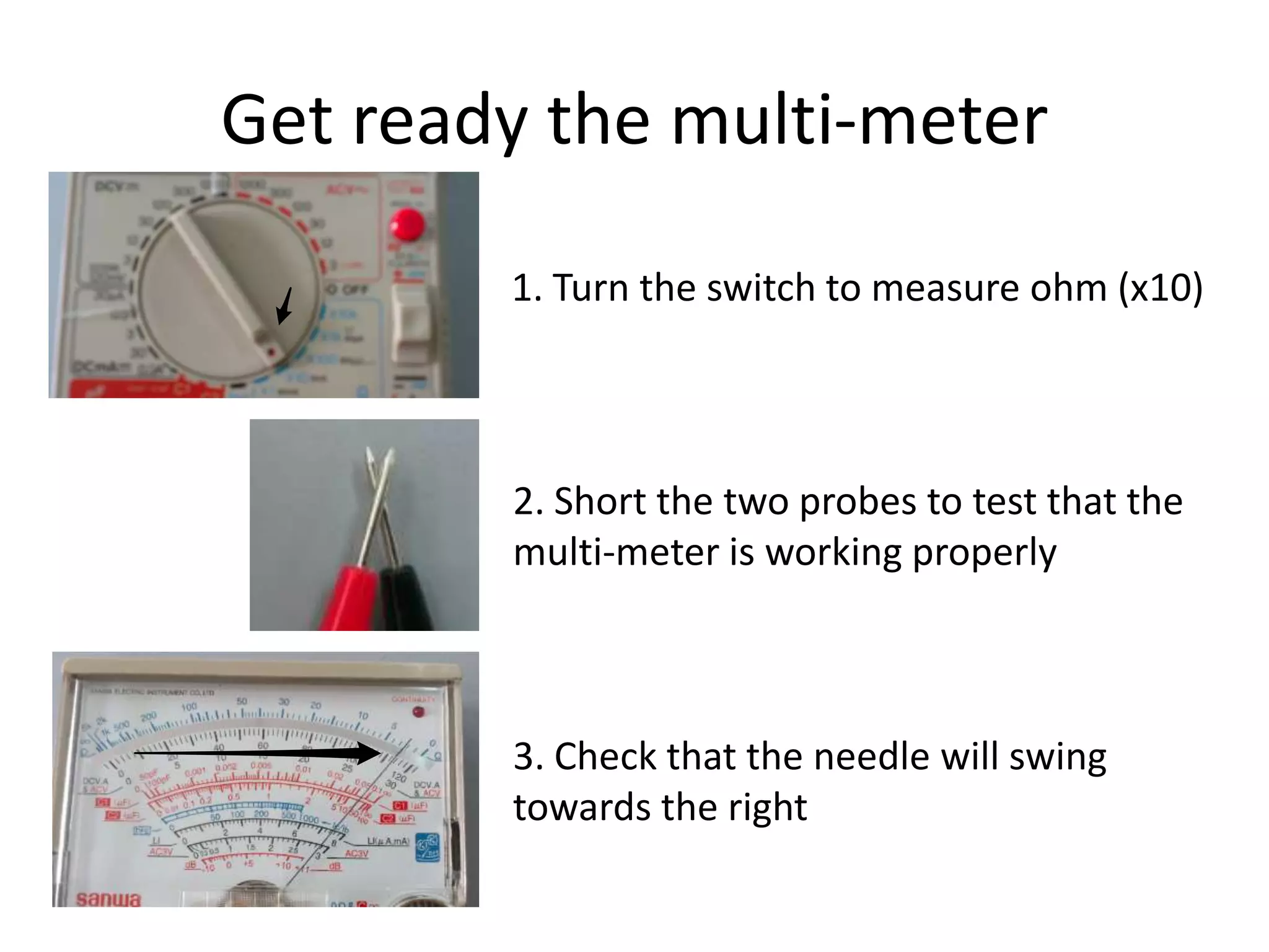
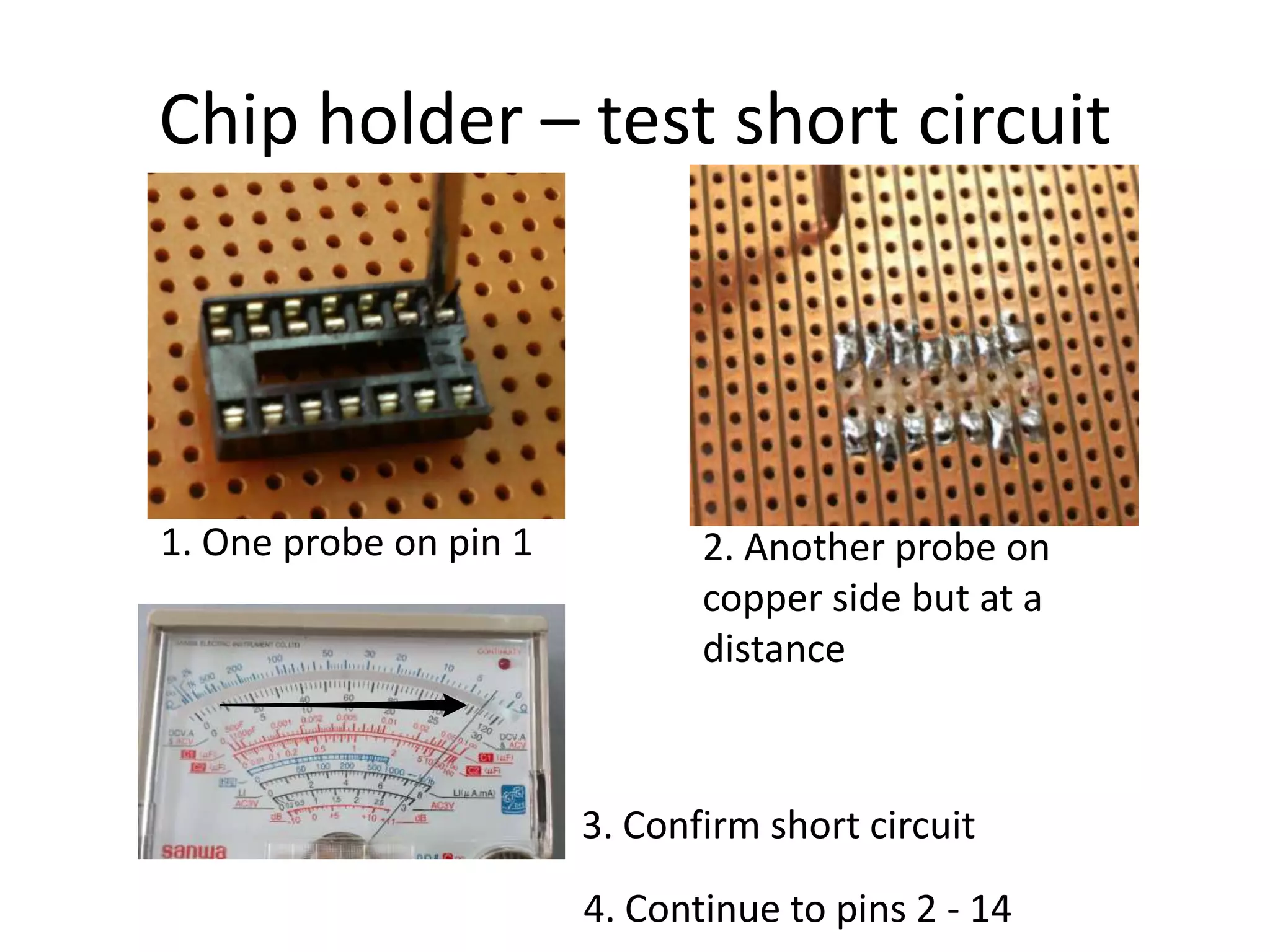
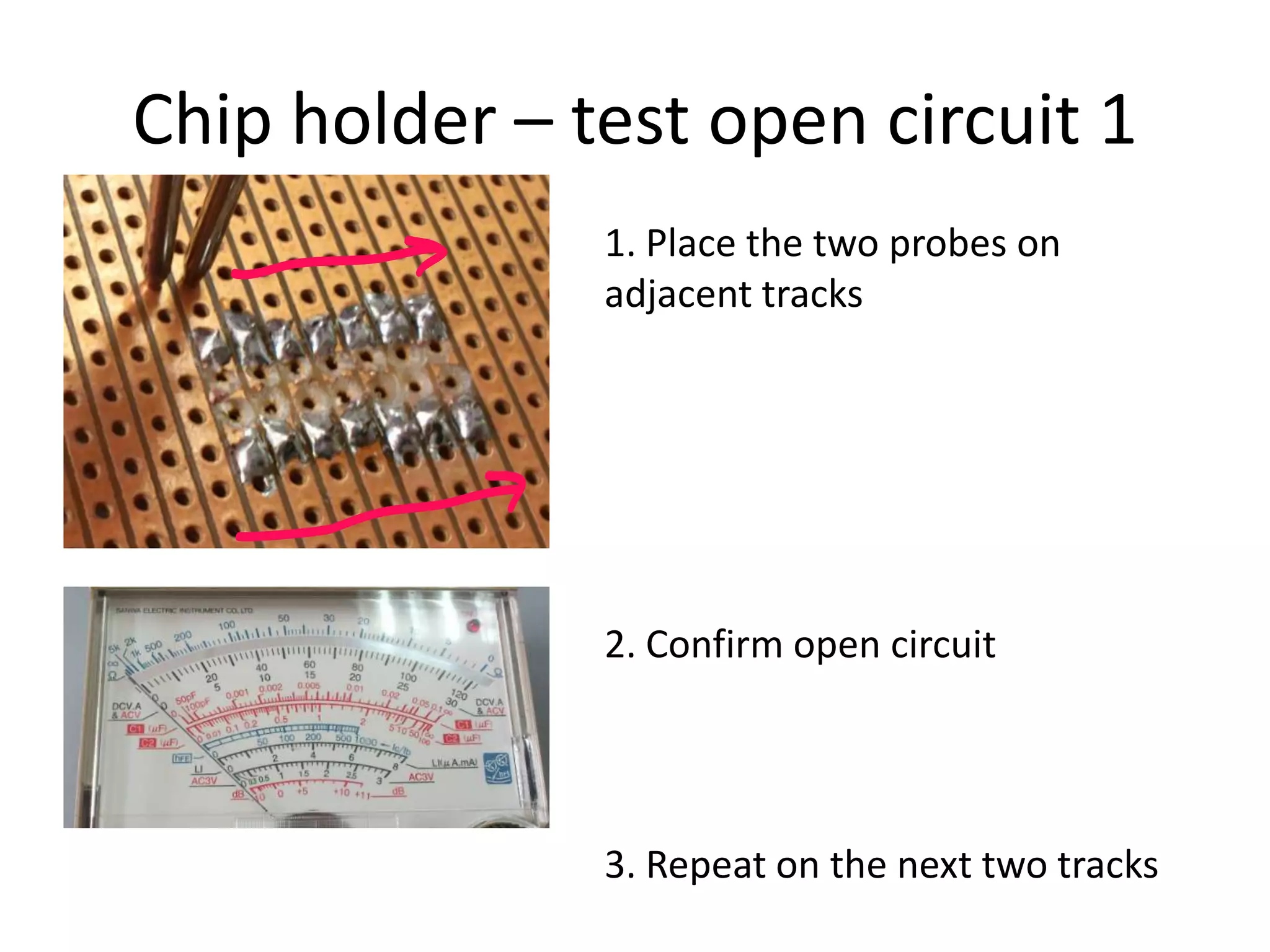
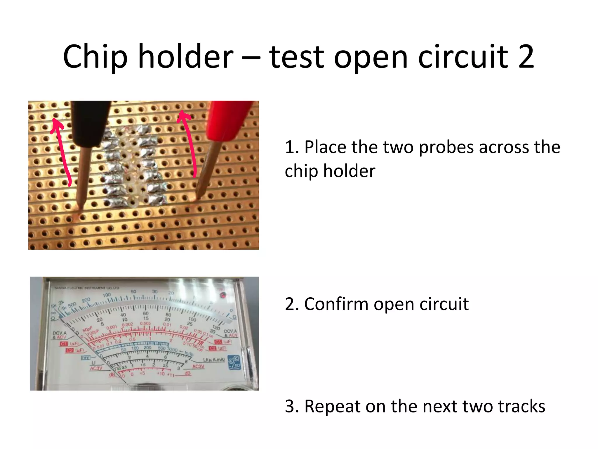
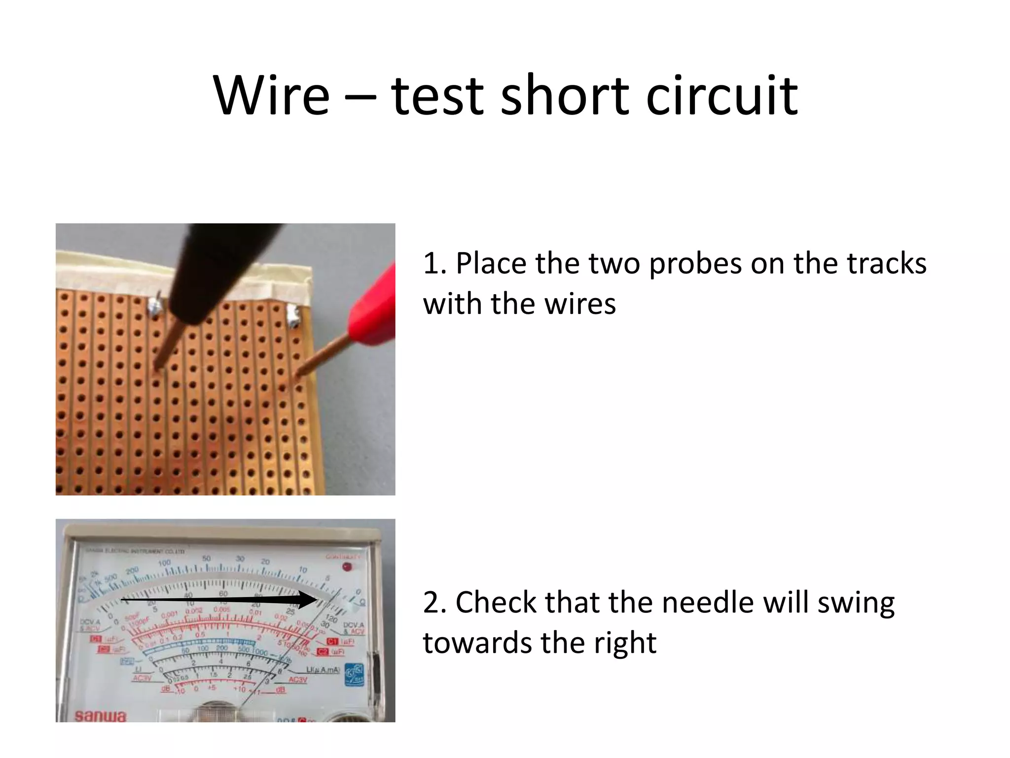
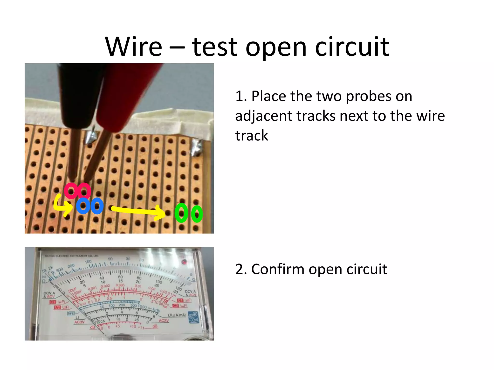
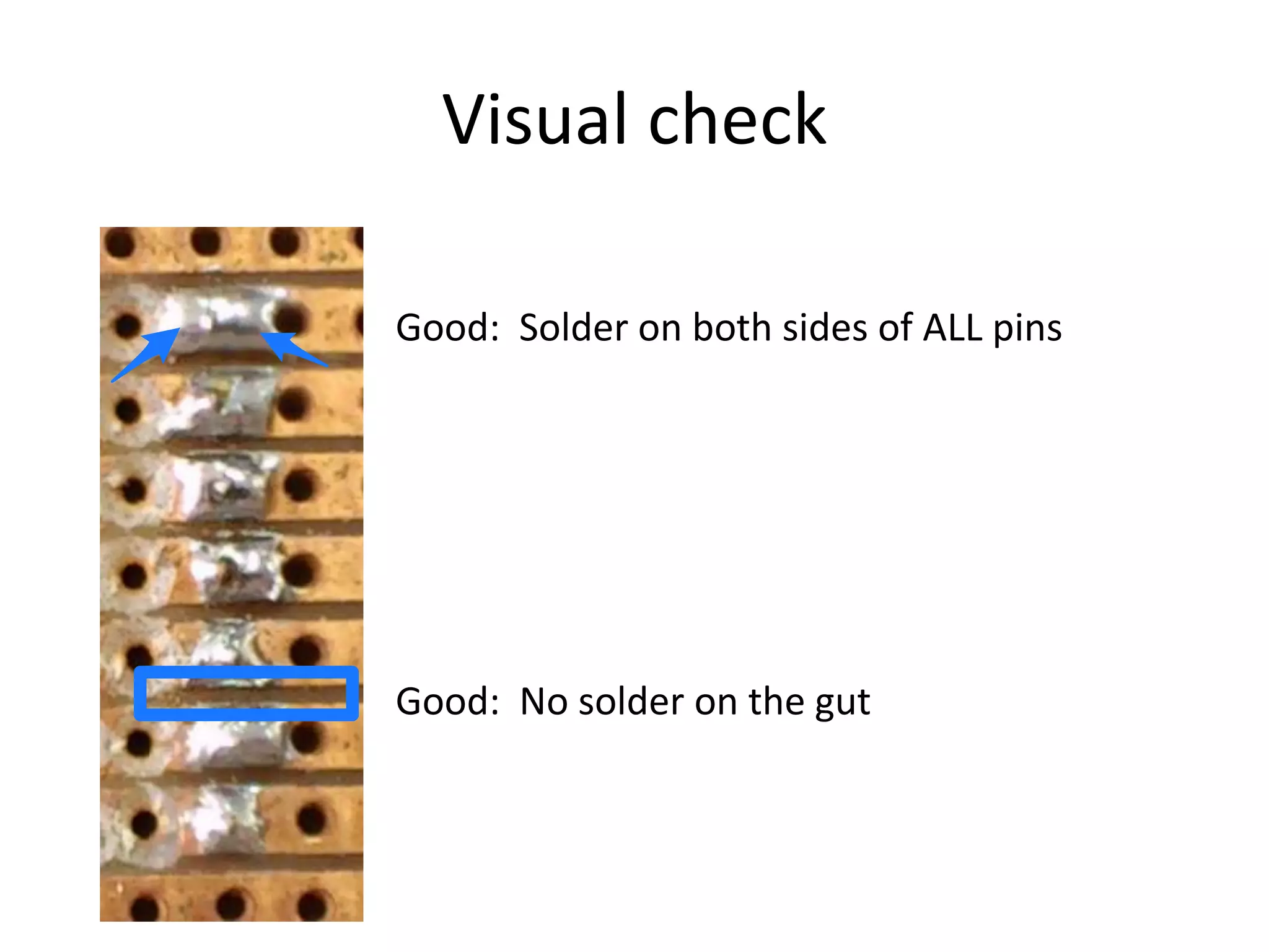
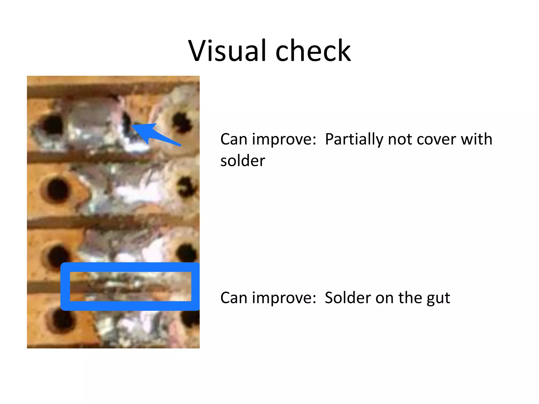


The document provides instructions for testing connectivity using a multi-meter. It describes steps to test that the multi-meter is working properly by creating a short circuit. It then lists steps to test chips for short and open circuits at different pins and tracks. Similar steps are provided to test wires for short and open circuits. Finally, it describes what to visually check for during inspection and examples of issues that could be improved.