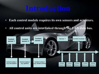
1. • Each control module requires its own sensors and actuators.
• All control units are interlinked through the CAN data bus.
Sensor 1 Control module 1
Control
Module 2
Control
Module 4
Control
Module 5
Control
Module 6
Control
Module 3
Coolant
sensor 1
Control module 1
(e.g. fuel system)
Coolant
sensor 2
Coolant
sensor 3
Control module 2
(e.g. ignition)
Control module 3
(e.g. climate control)
Introduction
2.
3. The CAN bus is an open system which
permits adaptation to various transmission
media such as copper or optical fiber cables.
Many individual modules are connected in parallel
to the CAN bus system.
What is CAN Bus….?
4. • CAN means (Controller Area Network)
• BUS means (Bidirectional Universal Serial interface)
• It is serial bus communications protocol developed Bosch in
1980.
5. A CAN data bus can be compared to an
omnibus.
Whilst the omnibus transports a large
number of persons, the CAN data bus
transports a large volume of information.
6. The CAN data bus consists of a special
twisted two-core cable.
CAN
Transceiver
CAN
Transceiver
CAN L
CAN H
120Ω
120Ω
7. Why two wires …..?
I - To prevent electromagnetic interference
II - To continue to serve in the event of a
cut in the wire
9. • The control unit receives
signals from the sensors,
processes them and passes
them on to the actuators.
• The CAN module controls
the data transfer process
for CAN messages.
• The transceiver is a
transmitter and receiver
amplifier.
10. Signal level
time
0 0 0
1
0
1
0
0V
5V
CAN Bus use binary system to transmit and receive
data on the two wire
Data transfer depends on the voltage intermittent
Binary System
12. CAN high
CAN low
Example :
0
0
5
5
These 2 wires carry anti-phase signals in opposite
directions to minimize noise interruption that
simultaneously interferes on the bus.
Difference CAN high to CAN low
13. Four types of messages:
• Data frame
• Remote frame
• Error frame
• Overload frame
Here we limit the discussion to the data frame :
1. SOF: start-of-frame
2. Identifier
3. RTR : remote transmission request
4. Data
5. CRC : cyclic redundancy checksum
6. ACK : acknowledgment
7. EOF: end of a message frame
CAN Message Types
14. Every datagram within the CAN Bus consists of a
number of bits, which are divided into different
fields.
1 12 6 0 to 64 16 2 7 3
Start bit = beginning of message
Identifier = regulate the bus access control
and inform whether data is to be
requested or sent or whether
an error output takes place
Control field = specifies how many bytes
are present in the data field
Data field = with the actual information contents
of the message
Control field = for checking whether correct
data transmission took place
Confirmation field = contains the confirmation signal
of all receivers (control units)
End of the message
3 bit rest-state on the CAN until the the next message
Data Frame
15. When digital information is exchanged, we talk
of data transmission
1 0 1 0 0 0 1 1
1 0 1 0 0 0 1 1
16. 1- Brake 2- Engine 3- Gearbox
priority Data protocol Status field
1
2
3
Brake
Engine
Gearbox
001 1010 0000
010 1000 0000
100 0100 0000
Priority of Message
17. What is the speed of CAN….?
• CAN C - Engine CAN (also known as chassis CAN) Fast
communication speeds 125 kbps or 500 kbps
• CAN B - Interior CAN (also known as body CAN) Communication
speed 83 .3kbps
CAN bus systems
CAN A
CAN B
CAN-C
CAN D
Interior bus
Engine bus
Diagnosis bus
10 kbits
83.3 - 125 kbits
125 - 500 kbits
1 Mbits
Unused now
18. Central gateway control unit
In the vehicle a distinction is made between a CAN C and
CAN B. The interface of the two CAN data buses (gateway)
which also represents the interface between the control units
on the CAN data bus and the line to the data link connector
for STAR DIAGNOSIS.
65. Advantages of CAN Bus
• Lower cost of wiring
• Fewer sensors
• Fewer plug connections
• Fewer pins at control modules
• Weight reduction
• Better diagnosis
• Fast transfer rates
• Several messages can be transferred in succession on
the same line
The main advantage of CAN over alternative networks is
66. CAN - Application
• Automotive
• Industrial controls
• Medical monitoring systems
• Factory automation
• Industrial machine control
• Lifts and escalators
• Building automation
• Non-industrial control
• Non-industrial equipment
• ATLAS B-field Monitoring