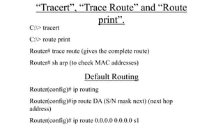
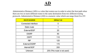
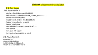
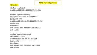
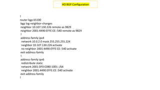
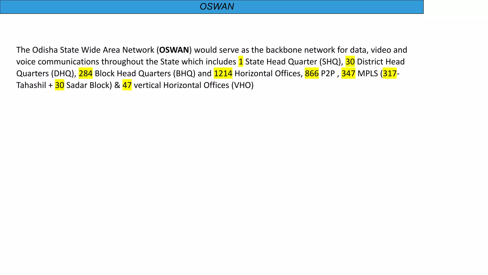
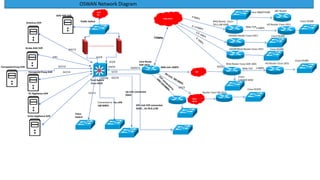
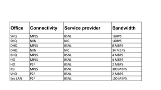
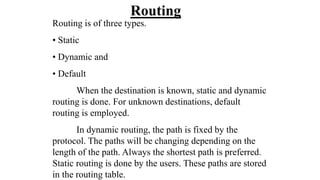
The Odisha State Wide Area Network (OSWAN) would serve as the backbone network for data, video and voice communications throughout the State of Odisha. The network connects 1 State Head Quarter, 30 District Head Quarters, 284 Block Head Quarters, and 1214 Horizontal Offices across the state. The OSWAN uses equipment from Cisco, BSNL, and NIC to setup connections between offices using technologies like MPLS, P2P, optical fiber, and microwave.


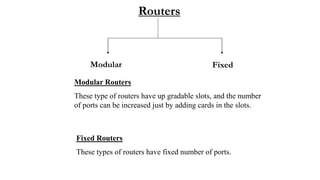
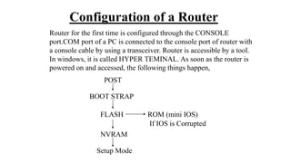
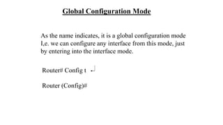
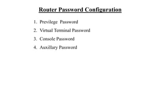
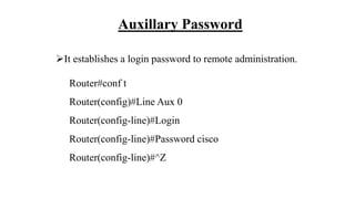
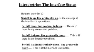
![In Setup mode, there will be a message,
“Would You Like To Enter The Initial Configuration [Y/N]” :
If “Y” then, initial configuration starts.
If “N” would you like to terminate the auto installation?
Press “RETURN” to get started……You will land on the default prompt
of the Router “ ROUTER >”.
Router>_](https://image.slidesharecdn.com/oswan-230719071801-05721135/85/OSWAN-pptx-12-320.jpg)
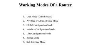
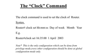
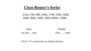
![Backup of IOS Image
Router#Copy Flash:(Press Tab key) Tftp
Address or name of the remote host [ ]? (Ip address of tftp)
Destination file name [ ] ? (Press enter key or a name)
Backup of Configuration
Router#Copy Startup-config Tftp
Address or name of the remote host [ ]? (Ip address of tftp)
Destination file name [ ] ? (Give a name)](https://image.slidesharecdn.com/oswan-230719071801-05721135/85/OSWAN-pptx-33-320.jpg)
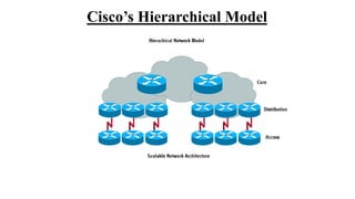
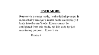
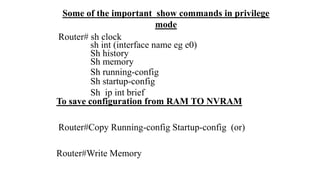
![Upgrading IOS Image
Note: This process can only be done by Console Session.
Router#Copy tftp Flash:
Address or name of remote host []?
Source file name []?
Destination file name []?
Erase Flash: before copying [confirm]?
Erasing the Flash file system will remove all files: continue?
[confirm]
Erasing device eeeeeeee……….eeeeeee.eee.eeee.ee
Loading!!!!!!!!!!!!!!!!!!!!!!!!!!!!!…….!!!!…….!!!!!!](https://image.slidesharecdn.com/oswan-230719071801-05721135/85/OSWAN-pptx-34-320.jpg)


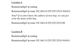
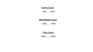
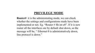
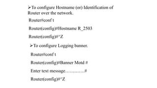
![Router# sh ip route
C 192.168.1.0/24 directly connected to E0
C 10.0.0.0/8 “ ‘ “ “ S0
S 192.168.2.0/24 [1/0] via 10.0.0.2
•“S” represents static. [a/b] ~ [1/0], here a=1 is the
administrative distance value and b has no significance in
static routing. For static and default routing b can be 0 or 1.
• lesser the administrative distance value, higher the
preference.](https://image.slidesharecdn.com/oswan-230719071801-05721135/85/OSWAN-pptx-45-320.jpg)