Downloaded 288 times

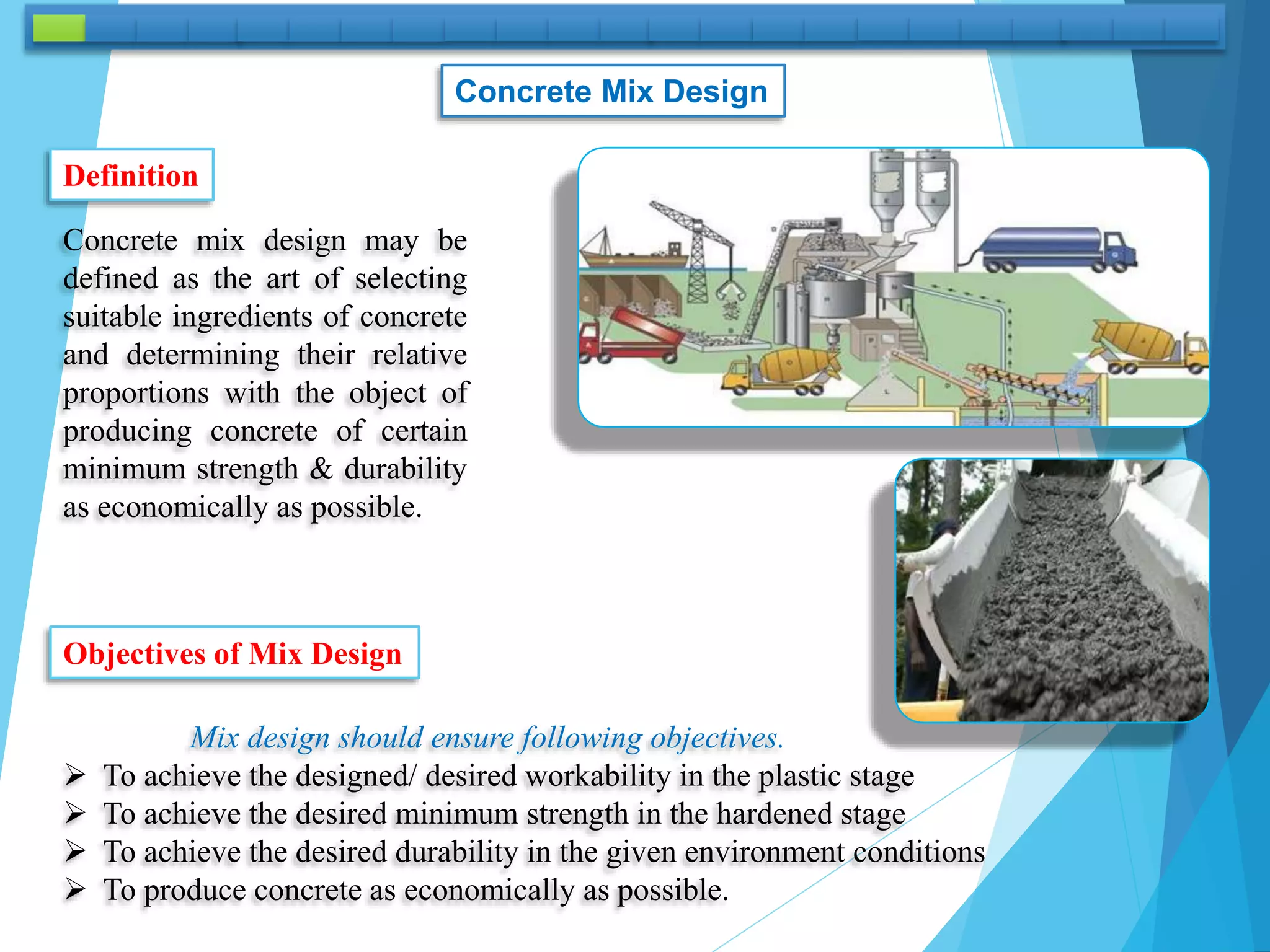
![CONCRETE MIX DESIGN
Weight & Absolute Volume Method
( ACI Method )
Is the process of selecting suitable ingredients of concrete & determining their
relative quantities with the purpose of producing an economical concrete which
has certain minimum properties [ notably Workability, Strength & Durability].
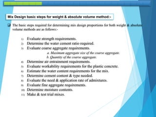
Mix design
The following three qualities are required of properly proportioned concrete mixers:-
1) Acceptable workability of freshly mixed concrete.
2) Durability, strength & uniform appearance of hardened concrete.
3) Economy.
Several mix design methods have been developed over the years, ranging from an arbitrary
volume method. [e.g. (1:2:4) cement, Sand, Gravel].to the weight & absolute – volume
method.
The weight method provides relatively simple techniques for estimating mix proportions using
an assumed or known unit weight of concrete.
The absolute volume methods uses the specific gravity of each ingredient to calculate the unit
volume each will occupy in unit volume of concrete.](https://image.slidesharecdn.com/8-220910110744-bbba6e0e/85/Concrete-Mix-Design-pptx-5-320.jpg)
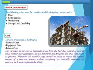
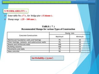
![1 – STRENGTH REQUIREMENTS:-
In order to compute the strength requirements for concrete mix design, three quantities
must be known:-
1) The specified compressive strength [fc
/)].
Cylinder at 28 days [ (fc
/) = 0.80 (fcu ) ] Cube at 28 days.
Cube at 28 days [ (fcu ) = 1.25 (fc
/) ] Cylinder at 28 days.
2) The variability or standard deviation (S), of concrete.
3) The allowable risk of making concrete with an unacceptable strength.
The standard deviation in the strength is determined for a plant by making batches of
concrete, testing the strength for many samples and computing the standard deviation.
The allowable risk has been established by the [(ACI)], One of the risk rules has been
established, states that there should be less than [(10%)] chance that the strength of a
concrete mix is less than the specified strength.
1. Standard deviation (S) is a measure of the dispersion or spread of the results.
2. The arithmetic mean [(X‾)] is simply the average of test results of all specimens tested.](https://image.slidesharecdn.com/8-220910110744-bbba6e0e/85/Concrete-Mix-Design-pptx-7-320.jpg)
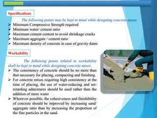
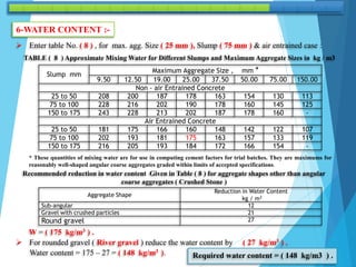
![fcŕ= fc
/ + 1.34 (S) ……………… (1)
Where:-
fcŕ = Required average compressive strength (MPa) .
fc
/ = Specified compressive strength (MPa)
S = Standard deviation (MPa)
For mixes with a large standard deviation in strength, there is another risk criterion that requires.
fcŕ = fc
/ + 2.33 (S) – (3.45) ……… (2)
The larger of equations [(1) & (2)], will govern.
The standard deviation should be determined from at least (30) strength results.
If (S) is computed from [(15) to (30)] samples, then
fcŕ= fc
/ + 1.34 (S¯) …………..…… (3)
0r
fcŕ = fc
/ + 2.33 (S¯) – (3.45) ……… (4)
Where (S¯) is the product of
(S) multiplied by the following
modification factors(f). i.e,
S¯ = S . f](https://image.slidesharecdn.com/8-220910110744-bbba6e0e/85/Concrete-Mix-Design-pptx-8-320.jpg)
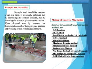
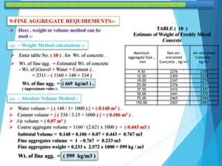
![ If fewer than (15) test are available, the following adjustments are made to the specified strength
instead of using equations [(1), ( 2 ) ,( 3 ) and (4)] as shown below:
Specified compressive strength
fc
/ ( MPa )
Required average compressive strength
fcŕ ( MPa )
< 20.7
20.7 to 34.5
> 34.5
fc
/ + 6.9
fc
/ + 8.3
fc
/ + 9.7
Example:
The design engineer specifies a concrete strength of [(31.0) MPa], Determine the
required average compressive strength for:-
(A) - A new plant where (S) is unknown.
(B) - A plant where [(S=3.6) MPa], for (17) test results.
(C) - A plant with extensive history of producing concrete with [(S=2.4) MPa].
(D) - A plant with extensive history of producing concrete with [(S=3.8) MPa].](https://image.slidesharecdn.com/8-220910110744-bbba6e0e/85/Concrete-Mix-Design-pptx-9-320.jpg)
![(A) – for fc‾ = 31 MPa , as (S) is unknown.
fcŕ = fc‾ + 8.3
= 31.0 + 8.3 = 39.3 MPa
Specified
compressive strength
fc
/ ( MPa )
Required average
compressive strength
fcŕ ( MPa )
< 20.7
20.7 to 34.5
> 34.5
fc
/ + 6.9
fc
/ + 8.3
fc
/ + 9.7
(B) - As (S) is based on ( 17 ) test results , between ( 15 – 30 ) so modified (S) to be used .
find ( f ) by inter potation.
f = {(1.16) – [(1.16 –1.08) / (20 –15)] × (17 –15)} f =1.13
i.e.
S¯ = f * S = 1.13×3.6 = 4.1 MPa
Now determine (fcŕ) basing on equ. ( 1 ) & ( 2 ) .
fcŕ= fc‾ + 1.34 (S)
fcŕ= 31.0 + [ (1.34)×(4.1) ] = 36.5 MPa
Or
fcŕ = fc‾ + 2.33 (S) – (3.45)
= {31.0 + [(2.33) × (4.1)] – (3.45)} = 37.1 MPa [govern]
Use fcŕ = 37.1 MPa
Number of tests (n) Modification Factor (f)
15
20
25
30 or more
1.16
1.08
1.05
1.00](https://image.slidesharecdn.com/8-220910110744-bbba6e0e/85/Concrete-Mix-Design-pptx-10-320.jpg)
![(C) - As (S) is based on more results , than (30 ) results
(fcŕ) to be calculated directly from equ. ( 1 ) & ( 2 ) .
fcŕ= fc‾ + 1.34 (S)
= {31.0 + [ (1.34)×(2.4) ] } = 34.2 Mpa [govern]
Or
fcŕ = fc‾ + 2.33 (S) – (3.45)
= {31.0 + [(2.33) × (2.4)] – (3.45)} = 33.1 MPa
Use fcŕ = 34.2 MPa
(D) Same as C
fcŕ= fc‾ + 1.34 (S)
= 31.0 + [ (1.34)×(3.8) ] = 36.1 MPa
or
fcŕ = fc‾ + 2.33 (S) – (3.45)
= {31.0 + [(2.33) × (3.8)] – (3.45)} = 36.4 MPa [govern]
Use fcŕ = 36.4 MPa](https://image.slidesharecdn.com/8-220910110744-bbba6e0e/85/Concrete-Mix-Design-pptx-11-320.jpg)
![Solution :
1- STRENGTH REQUIREMENTS :-
S = 2.4 MPa ( enough samples so that no correction is needed )
fcŕ= fc‾ + 1.34 (S) = 24.1 + [ (1.34)×(2.4) ] = 27.3 MPa [govern] Or
fcŕ = fc‾ + 2.33 (S) – (3.45) = {24.1 + [(2.33) × (2.4)] – (3.45)} = 26.2 MPa fcŕ = 27.3 MPa
2 - WATER – CEMENT RATIO:-
For fcŕ = 27.3 (MPa)
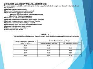
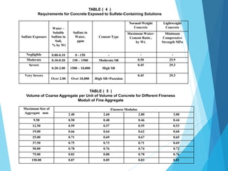
TABLE ( 1 ) Typical Relationship between Water-Cement Ratio and Compressive Strength of Concrete
Average compressive strength
at 28 Days f'cr ( MPa )
Water – Cement Ratio , by Weight
Non-air-entrained concrete Air –entrained concrete
41.4 0.41 -
34.5 0.48 0.40
27.6 0.57 0.48
20.7 0.68 0.59
13.8 0.82 0.74
Enter table No. ( 1 ) , & by interpolation [ (W/C) = 0.48 ].
Δ fc‾ = 27.6 – 20.7 = 6.9 (MPa)
Δ (W/C) = 0.59 – 0.48 = 0.11
For ( 27.6 -27.3 ) = 0 .3 Δ (W/C) = {( 0.3 × 0.11 ) / 6.9 } = 0.0047
(W/C) = 0.48 + 0.0047 = 0.48
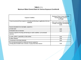
0](https://image.slidesharecdn.com/8-220910110744-bbba6e0e/85/Concrete-Mix-Design-pptx-13-320.jpg)
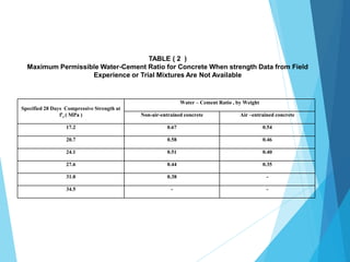
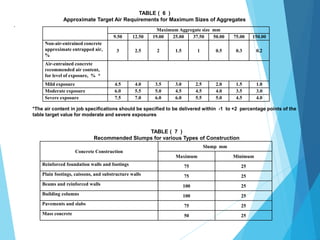
![[ ( W/C ) = 0.45 ] The smaller value of table ( 1 & 3 ) governs
For exposure condition ( exposed to freezing & thawing subjected the de-icing chemicals ) .
Enter table No.( 3 ) , Max. Permissible [ ( W/C ) = 0.45 ].
TABLE ( 3 )
Maximum Water-Cement Ratio for Various Exposure Conditions
Exposure Condition
Maximum Water-Cement Ratio
for Normal-Weight Concrete
by Weight
Concrete protected from exposure to freezing and thawing or
application of de-icer chemicals
Select water-cement ratio on
basis of strength ,workability
and finishing needs
Concrete intended to be watertight , exposed to :
a. Fresh water 0.50
b. Brackish water or Seawater 0.45
Concrete exposed to freezing and thawing in a moist condition (
air-entrained concrete)
a. Curbs , gutters , guardrails, or this sections 0.45
b. Other elements 0.50
c. In presence of de-icing chemicals 0.45
For corrosion protection for reinforced concrete exposed to
de-icing salts, brackish water, seawater, or spray from these
sources
0.40](https://image.slidesharecdn.com/8-220910110744-bbba6e0e/85/Concrete-Mix-Design-pptx-14-320.jpg)
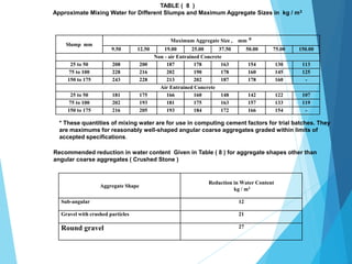
![7-CEMENT CONTENT REQUIREMENTS:-
For [(W/C) = 0.45 ] & water content = ( 148 kg/m3 )
[ Cement Content = ( 148 / 0.45 )] = ( 329 kg/m3 )
Having minimum cement content requirement for freeze & thawing & de-icing chemicals
= ( 334 kg/m3 )
Cement Content = ( 334 kg/m3 )
8-ADMIXTURE :-
For Air content = ( 7 % ) , Cement Content = ( 334 kg/m3 ) .
Admixture required = { 6.3 × 7 × ( 334 /100 )} = ( 147 ml /m3 ) .
Admixture Required = ( 147 ml /m3 ) .](https://image.slidesharecdn.com/8-220910110744-bbba6e0e/85/Concrete-Mix-Design-pptx-19-320.jpg)
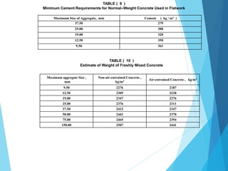
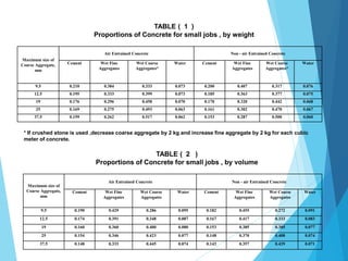
![10-MOISTURE CORRECTIONS:-
Mix design should be based on (S.S.D.) [ Saturation Surface Dry ], condition for fine &
coarse aggregate .
The final step in the mix design process is to adjust the weight of water & aggregates to
acount for the existing moisture content of the aggregates. If moisture content of the
aggregates is more than the (S.S.D.) moisture content , the weight of mixing water is reduced
by an amount equal to the free weight of the moisture on the aggregate.
Similarly, if the moisture content is below, (S.S.D.) moisture content, the mixing water must
be increased.
Coarse aggregates : Need 1160 kg / m3 in SSD condition , so increase by 3 % for excess
moisture
Moist coarse aggregates = 1160 x 1.03 = 1195 kg / m3
Fine aggregates : Need 599 kg / m3 in SSD condition , so increase by 4 % for excess
moisture
Moist fine aggregates = 599 x 1.04 = 623 kg / m3
Water : Reduce for free water on aggregates
= 148 – 1160 ( 0.03 – 0.004 ) - 599 ( 0.04 – 0.008 ) = 99 kg / m3](https://image.slidesharecdn.com/8-220910110744-bbba6e0e/85/Concrete-Mix-Design-pptx-21-320.jpg)
![Summary : Water 99 kg
Cement 334 kg
Fine aggregates 623 kg
Coarse aggregates 1195 kg
Admixture 147 ml
Concrete mix W (Water): C ( Cement) : F ( Fine agg.) : C ( Coarse agg.) : Ad (Admixture )
99 : 334 : 623 : 1195 : 147ml
0.2964 : 1 : 1.8653 : 3.5778 : 147 ml
11 - TRIAL MIXES:-
To be done on site, to check the mix design.
Trial batch using three (Cubes) [ (150 ) × (150 ) × (150 ) mm ] ,
or cylinder [( 150 ) × ( 300 ) mm ] , cured for [ (28) days ] and tested for compression strength.
Finally mix design ratio should be based on the weight of the mix ingredients & the site
engineer can convert it to volumes.](https://image.slidesharecdn.com/8-220910110744-bbba6e0e/85/Concrete-Mix-Design-pptx-22-320.jpg)

The document details concrete mix design, focusing on the selection of suitable ingredients and their proportions to achieve desired strength, workability, and durability while being cost-effective. It outlines objectives such as ensuring economic production without compromising on quality, as well as key considerations like cost, workability, strength, and durability. Various methods for mix design are discussed, including guidelines for evaluating strength requirements, water-cement ratios, aggregate requirements, and proper trial mix procedures.


![Geotechnical Engineering-II [Lec #11: Settlement Computation]](https://cdn.slidesharecdn.com/ss_thumbnails/11-181020124840-thumbnail.jpg?width=640&height=640&fit=bounds)


![concretemixdesign-150329082925-conversion-gate01[1].pptx](https://cdn.slidesharecdn.com/ss_thumbnails/concretemixdesign-150329082925-conversion-gate011-251224211910-ae195a00-thumbnail.jpg?width=640&height=640&fit=bounds)


