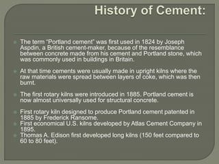
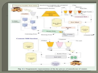
Prepared by:
Bhargavi J
Assistant Professor
Civil Engg Dept
RYMEC
Ballari
 Cement
 Manufacturing of cement
 Chemical composition of cement
 Hydration of cement
 Types of cement
 Tests on Cement
 Steps to reduce carbon footprint
 Alternative to river sand: M-sand
 Fine aggregate
 Coarse aggregate
 Test on FA & CA
 Water- Qualities of water
Cement is defined in many ways as follows,
 Cement is an extremely ground material
having adhesive and cohesive properties,
which provide a binding medium for the
discrete ingredients.
 Cement, any material that hardens and
becomes strongly adhesive after application.
 Manufactured substance consisting of
gypsum plaster, or Portland cement.
 The term “Portland cement” was first used in 1824 by Joseph
Aspdin, a British cement-maker, because of the resemblance
between concrete made from his cement and Portland stone, which
was commonly used in buildings in Britain.
 At that time cements were usually made in upright kilns where the
raw materials were spread between layers of coke, which was then
burnt.
 The first rotary kilns were introduced in 1885. Portland cement is
now almost universally used for structural concrete.
 First rotary kiln designed to produce Portland cement patented in
1885 by Frederick Ransome.
 First economical U.S. kilns developed by Atlas Cement Company in
1895.
 Thomas A. Edison first developed long kilns (150 feet compared to
60 to 80 feet).
 The raw materials required for manufacture of Portland
cement are calcareous materials, such as limestone or
chalk, and argillaceous material such as shale or clay.
 The process of manufacture of cement consists of
grinding the raw materials, mixing them intimately in
certain proportions depending upon their purity and
composition and burning them in a kiln at a
temperature of about 1300 to 1500°C, at which
temperature, the material sinters and partially fuses to
form nodular shaped clinker.
 The clinker is cooled and ground to fine powder with
addition of about 3 to 5% of gypsum.
 The product formed by using this procedure is Portland
cement.
 There are two processes known as “wet” and “dry”
processes depending upon whether the mixing and
grinding of raw materials is done in wet or dry
conditions.
WET PROCESS
 In the wet process, the limestone brought from
the quarries is first crushed to smaller fragments.
 The rotary kiln is an important component of a
cement factory. It is a thick steel cylinder of
diameter anything from 3 metres to 8 metres, lined
with refractory materials, mounted on roller
bearings and capable of rotating about its own axis
at a specified speed.
 The length of the rotary kiln may vary anything
from 30 metres to 200 metres.
 In the dry and semi-dry process the raw materials are crushed
dry and fed in correct Proportions into a grinding mill where
they are dried and reduced to a very fine powder.
 The dry powder called the raw meal is then further blended
and corrected for its right composition and mixed by means of
compressed air.
 The aerated powder tends to behave almost like liquid and in
about one hour of aeration a uniform mixture is obtained.
 The blended meal is further sieved and fed into a rotating disc
called granulator.
 A quantity of water about 12 per cent by weight is added to
make the blended meal into pellets.
 This is done to permit air flow for exchange of heat for further
chemical reactions and Conversion of the same into clinker
further in the rotary kiln.
 In cement manufacturing, there are two
major sources of CO2 emissions. The
primary source (60% of total emissions) is the
calcination of limestone (CaCO3). Limestone,
when heated to above 900 ºC, converts to
quick lime (CaO), releasing CO2.
 The secondary source (40% of total
emissions) is the burning of coal/fuel to
provide the heat required for the calcination
and clinkering process.
 In terms of weight, roughly 900 g of CO2 is
produced as a by-product, for every 1 kg of
cement produced. This is the uniqueness of
the cement process, wherein CO2 is
produced in substantial quantity, along with
the main product (cement).
 Over the last thirty years, the specific fuel
consumption of cement manufacturing has
decreased by 40%, which directly reduces the
CO2 emission by the same magnitude.
 Furthermore, coal, which is conventionally
used for combustion, is increasingly being
replaced by alternative fuels like Municipal
solid waste (MSW), rubber tires, dried
sewage sludge, etc.
 In order to have a true zero-emission cement
plant, more work needs to be done
 There are ready solutions available that can
capture the emitted CO2 from the process: Oxyfuel
combustion, chemical looping, all-electric process
heating, etc. are some of the technologies that are
in various stages of development for carbon(CO2)
capture.
 Storage of the captured CO2 is slightly more
complicated and, presently, the most viable option
seems to be the pumping of CO2 into used oil
wells and other geological formations. The
utilization of captured CO2 into other beneficial
minerals is still in its early stages. However,
installing these technologies in a process like
cement is not viable in today’s economy
 The price of cement should include both the
“cost of cement manufacturing” as well as the
“cost of not emitting CO2”
 Establishing a market for CO2 is the most
efficient way of calculating its cost. Initial
steps along this line are already been taken in
the form of carbon credits in the EU. This
needs to be made more universal with strong
regulation and covering all sources of carbon
emission, both industrial and non-industrial.
And this market should become global with all
countries partnering and becoming part of it
The manufacturer can market their “green
cement” by highlighting the fact that "Zero
CO2” is emitted during its production,
verified by a third-party
The solution would be to re-align the
economy by rewarding environmentally
sustainable products which will ensure
that cement production becomes more
sustainable in the long run.
 The raw materials used for the manufacture of
cement consist mainly of lime, silica, alumina and
iron oxide.
 These oxides interact with one another in the kiln
at high temperature to form more complex
compounds. The relative proportions of these
oxide compositions are responsible for influencing
the various properties of cement; in addition to rate
of cooling and fineness of grinding.
 Table 1 shows the approximate oxide composition
limits of ordinary Portland cement.
As mentioned earlier the oxides present in
the raw materials when subjected to high
clinkering temperature combine with each
other to form complex compounds.
The identification of the major compounds
is largely based on R.H. Bogue’s work and
hence it is called “Bogue’s Compounds”.
 The four compounds usually regarded as
major compounds are listed in table
The equations suggested by Bogue for
calculating the percentages of major
compounds are given below.
C3S = 4.07 (CaO) – 7.60 (SiO2) – 6.72
(Al2O3) – 1.43 (Fe2O3) – 2.85 (SO3)
C2S = 2.87 (SiO2) – 0.754 (3CaO.SiO2)
C3A = 2.65 (Al2O3) – 1.69 (Fe2O3)
C4AF= 3.04 (Fe2O3)
 In addition to the four major compounds, there are
many minor compounds formed in the kiln.
 Two of the minor oxides namely K2O and Na2O
referred to as alkalis in cement are of some
importance and Expressed in terms of Na2O.
These alkalis basically react with active silica in
aggregate and produce what is called alkali-silica
gel of unlimited swelling type under favorable
conditions of moisture and temperature in voids
and cracks and further it causes disruption and
pattern cracking.
 Tricalcium silicate and dicalcium silicate are the
most important compounds responsible for
strength. Together they constitute 70 to 80 per cent
of cement. The average C3S content in modern
cement is about 45 per cent and that of C2S is
about 25 per cent.
 The calculated quantity of the compounds in
cement varies greatly even for a relatively small
change in the oxide composition of the raw
materials.
 To manufacture a cement of stipulated compound
composition, it becomes absolutely necessary to
closely control the oxide composition of the raw
materials.
 SO3 also appear in cement analysis which comes
from adding gypsum (4-6) % during clinker
grinding.
 The Iraqi and British specification for normal high
rapid Portland cement pointed that SO3 content
must be between ( 3-2.5 )% according to type of
cement and C3A content.
 The percentage of MgO in cement which is
come from Magnesia compounds in raw
material is about ( 4-1)% and 5% as
maximum range to control expansion from
hydration of this oxide in hard concrete.
 An increase in lime CaO content beyond a
certain value makes it difficult to combine with
other compounds and free lime will exist in
the clinker which causes unsoundness in
cement.
 Insoluble residue is that part of the Cement
non-soluble in hydrochloric acid HCl and arise
mainly from non active silica to form cement
compounds dissolved in this acid therefore it
express the completeness of the chemical
reactions inside the rotary kiln.
 Anhydrous cement does not bind fine and coarse
aggregate. It acquires adhesive property only when
mixed with water.
 The chemical reactions that take place between
cement and water is referred as HYDRATION OF
CEMENT.
 The chemistry of concrete is essentially the chemistry
of the reaction between cement and water.
 On account of hydration certain products are formed.
These products are important because they have
cementing or adhesive value. The quality, quantity,
continuity, stability and the rate of formation of the
hydration products are important.
 Anhydrous cement compounds when mixed with
water, react with each other to form hydrated
compounds of very low solubility.
 The hydration of cement can be visualized in two
ways. The first is “through solution” mechanism.
 In this the cement compounds dissolve to produce
a supersaturated solution from which different
hydrated products get precipitated.
 The second possibility is that water attacks cement
compounds in the solid state converting the
compounds into hydrated products starting from
the surface and proceeding to the interior of the
compounds with time.
 It is probable that both “through solution” and
“solid state” types of mechanism may occur during
the course of reactions between cement and water
The reaction of cement with water is
exothermic. The reaction liberates a
considerable quantity of heat. This
liberation of heat is called HEAT OF
HYDRATION.
This is clearly seen if freshly mixed cement
is put in a vaccum flask and the
temperature of the mass is read at
intervals.
 On mixing cement with water, a rapid heat
evolution, lasting a few minutes, occurs. This
heat evolution is probably due to the reaction
of solution of aluminates and sulphates
(ascending peak A).
 This initial heat evolution ceases quickly
when the solubility of aluminate is depressed
by gypsum. (decending peak A).
 Next heat evolution is on account of
formation of ettringite and also may be due to
the reaction of C3S (ascending peak B).
Refer below figure
 Different compounds hydrate at different rates
and liberate different quantities of heat.
 Fig. 1.3 shows the rate of hydration of pure
compounds. Since retarders are added to
control the flash setting properties of C3A,
actually the early heat of hydration is mainly
contributed from the hydration of C3S.
Fineness of cement also influences the rate
of development of heat but not the total heat.
 The total quantity of heat generated in the
complete hydration will depend upon the
relative quantities of the major compounds
present in a cement.
(a) Ordinary Portland Cement
(i ) Ordinary Portland Cement 33 Grade– IS 269:
1989
(ii ) Ordinary Portland Cement 43 Grade– IS 8112:
1989
(iii ) Ordinary Portland Cement 53 Grade– IS 12269:
1987
(b) Rapid Hardening Cement – IS 8041: 1990
(c) Extra Rapid Hardening Cement – –
(d) Sulphate Resisting Cement – IS 12330: 1988
(e) Portland Slag Cement – IS 455: 1989
(f ) Quick Setting Cement – –
(g) Super Sulphated Cement – IS 6909: 1990
(h) Low Heat Cement – IS 12600: 1989
(j ) Portland Pozzolana Cement – IS 1489 (Part I)
1991 (fly ash based)
– IS 1489 (Part II) 1991 (calcined clay
based)
(k) Air Entraining Cement – –
(l ) Coloured Cement: White Cement – IS 8042:
1989
(m) Hydrophobic Cement – IS 8043: 1991
(n) Masonry Cement – IS 3466: 1988
(o) Expansive Cement – –
(p) Oil Well Cement – IS 8229: 1986
(q) Rediset Cement – –
(r ) Concrete Sleeper grade Cement – IRS-T 40:
1985
(s) High Alumina Cement – IS 6452: 1989
(t) Very High Strength Cement –
 As per ASTM, cement is designated as Type I,
Type II, Type III, Type IV, Type V and other minor
types like Type IS, Type IP and Type IA IIA and
IIIA.
Type I
 For use in general concrete construction where the
special properties specified for Types II, III, IV and
V are not required (Ordinary Portland Cement).
Type II
 For use in general concrete construction exposed
to moderate sulphate action, or where moderate
heat of hydration is required.
Type III
 For use when high early strength is required
(Rapid Hardening Cement).
Type IV
 For use when low heat of hydration is
required (Low Heat Cement).
Type V
 For use when high sulphate resistance is
required (Sulphate Resisting Cement).
 ASTM standard also have cement of the type
IS. This consist of an intimate and uniform
blend of Portland Cement of type I and fine
granulated slag. The slag content is between
25 and 70 per cent of the weight of Portland
Blast-Furnace Slag Cement.
Type IP
This consist of an intimate and uniform
blend of Portland Cement (or Portland
Blast Furnace Slag Cement) and fine
pozzolana in which the pozzolana content
is between 15 and 40 per cent of the
weight of the total cement.
Type IA, IIA and IIIA
These are type I, II or III cement in which
air-entraining agent is interground where
air entrainment in concrete is desired.
 Ordinary Portland cement (OPC) is the most
important type of cement.
 The OPC was classified into three grades, namely
33 grade, 43 grade and 53 grade depending upon
the strength of the cement at 28 days when tested
as per IS 4031-1988.
 If the 28 days strength is not less than 33N/mm2, it
is called 33 grade cement, if the strength is not
less than 43N/mm2, it is called 43 grade cement,
and if the strength is not less then 53 N/mm2, it is
called 53 grade cement. But the actual strength
obtained by these cements at the factory are much
higher than the BIS specifications.
Generally use of high grade cements offer
many advantages for making stronger
concrete. Although they are little costlier
than low grade cement, they offer 10-20%
savings in cement consumption and also
they offer many other hidden benefits. One
of the most important benefits is the faster
rate of development strength.
This cement is similar to ordinary Portland
cement. As the name indicates it develops
strength rapidly and as such it may be
more appropriate to call it as high early
strength cement.
Rapid hardening cement develops at the
age of three days, the same strength as
that is expected of ordinary Portland
cement at seven days.
 A higher fineness of cement particles expose
greater surface area for action of water and also
higher proportion of C3S results in quicker
hydration. Consequently, Rapid hardening cement
gives out much greater heat of hydration during the
early period. Therefore, rapid hardening cement
should not be used in mass concrete construction
The use of rapid heading cement is recommended in
the following situations:
(a) In pre-fabricated concrete construction.
(b) Where formwork is required to be removed early
for re-use elsewhere,
(c ) Road repair works,
(d ) In cold weather concrete where the rapid rate of
development of strength reduces the vulnerability
of concrete to the frost damage.
 Extra rapid hardening cement is obtained by
intergrinding calcium chloride with rapid
hardening Portland cement
 The normal addition of calcium chloride
should not exceed 2 percent by weight of the
rapid hardening cement. It is necessary that
the concrete made by using extra rapid
hardening cement should be transported,
placed and compacted and finished within
about 20 minutes
Extra rapid hardening cement accelerates
the setting and hardening process.
The acceleration of setting, hardening and
evolution of this large quantity of heat in
the early period of hydration makes the
cement very suitable for concreting in cold
weather, The strength of extra rapid
hardening cement is about 25 per cent
higher than that of rapid hardening cement
at one or two days and 10–20 per cent
higher at 7 days.
 Ordinary Portland cement is susceptible to
the attack of sulphates, in particular to the
action of magnesium sulphate
 Sulphates in solution permeate into hardened
concrete and attack calcium hydroxide,
hydrated calcium aluminate and even
hydrated silicates.
 The above is known as sulphate attack.
 Sulphate attack is greatly accelerated if
accompanied by alternate wetting and drying
which normally takes place in marine
structures in the zone of tidal variations.
To remedy the sulphate attack, the use of
cement with low C3A content is found to
be effective. Such cement with low C3 A
and comparatively low C4AF content is
known as Sulphate Resisting Cement. In
other words, this cement has a high
silicate content. The specification generally
limits the C3A content to 5 per cent.
The use of sulphate resisting cement is
recommended under the following
conditions:
(a ) Concrete to be used in marine condition;
(b ) Concrete to be used in foundation and
basement, where soil is infested with
sulphates;
(c ) Concrete used for fabrication of pipes
which are likely to be buried in marshy
region or sulphate bearing soils;
(d ) Concrete to be used in the construction
of sewage treatment works.
 Portland slag cement is obtained by mixing
Portland cement clinker, gypsum and
granulated blast furnace slag in suitable
proportions and grinding the mixture to get a
thorough and intimate mixture between the
constituents
 It has low heat of hydration and is relatively
better resistant to chlorides, soils and water
containing excessive amount of sulphates or
alkali metals, alumina and iron, as well as, to
acidic waters, and therefore, this can be used
for marine works with advantage.
 This cement as the name indicates sets very early.
 The early setting property is brought out by
reducing the gypsum content at the time of clinker
grinding. This cement is required to be mixed,
placed and compacted very early.
 It is used mostly in under water construction where
pumping is involved. Use of quick setting cement
in such conditions reduces the pumping time and
makes it economical. Quick setting cement may
also find its use in some typical grouting
operations.
It is well known that hydration of cement is
an exothermic action which produces large
quantity of heat during hydration
A low-heat evolution is achieved by
reducing the contents of C3S and C3A
which are the compounds evolving the
maximum heat of hydration and increasing
C2S.
A reduction of temperature will retard the
chemical action of hardening and so
further restrict the rate of evolution of heat.
The rate of evolution of heat will, therefore,
be less and evolution of heat will extend
over a longer period.
Therefore, the feature of low-heat cement
is a slow rate of gain of strength. But the
ultimate strength of low-heat cement is the
same as that of ordinary Portland cement
 Portland Pozzolana cement (PPC) is manufactured
by the intergrinding of OPC clinker with 10 to 25
per cent of pozzolanic material
 A pozzolanic material is essentially a silicious or
aluminous material which while in itself possessing
no cementitious properties, which will, in finely
divided form and in the presence of water, react
with calcium hydroxide, liberated in the hydration
process, at ordinary temperature, to form
compounds possessing cementitious pro
 The pozzolanic materials generally used for
manufacture of PPC are calcined clay (IS 1489
part 2 of 1991) or fly ash (IS 1489 part I of 1991).
Use of PPC would be particularly suitable
for the following situations:
(a ) For hydraulic structures;
(b) For mass concrete structures like dam,
bridge piers and thick foundation;
(c ) For marine structures;
(d ) For sewers and sewage disposal works
etc.
 This cement is made by mixing a small amount of
an air-entraining agent with ordinary Portland
cement clinker at the time of grinding.
The following types of air-entraining agents could be
used:
(a) Alkali salts of wood resins.
(b) Synthetic detergents of the alkyl-aryl sulphonate
type.
(c ) Calcium lignosulphate derived from the sulphite
process in paper making.
(d) Calcium salts of glues and other proteins
obtained in the treatment of animal hides.
For manufacturing various coloured
cements either white cement or grey
Portland cement is used as a base. The
use of white cement as a base is costly.
With the use of grey cement only red or
brown cement can be produced.
Coloured cement consists of Portland
cement with 5-10 per cent of pigment
The process of manufacture of white
Portland cement is nearly same as OPC
The raw materials used are high purity
limestone (96% CaCo3 and less than
0.07% iron oxide).
The other raw materials are china clay with
iron content of about 0.72 to 0.8%, silica
sand, flourspar as flux and selenite as
retarder. The fuels used are refined
furnace oil (RFO) or gas.
Sea shells and coral can also be used as
raw materials for production of white
cement.
Testing of cement can be brought under two
categories:
(a) Field testing
(b) Laboratory testing
Field Testing
It is sufficient to subject the cement to field tests
when it is used for minor works. The
following are the field tests:
(a) Open the bag and take a good look at the
cement. There should not be any visible
lumps. The color of the cement should normally be
greenish grey.
(b) Thrust your hand into the cement bag. It must
give you a cool feeling. There should
not be any lump inside.
(c) Take a pinch of cement and feel-between
the fingers. It should give a smooth and not a
gritty feeling.
(d) Take a handful of cement and throw it on a
bucket full of water, the particles should float
for some time before they sink.
Laboratory testing
 For using cement in important and major
works it is incumbent on the part of the user
to test the cement in the laboratory to confirm
the requirements of the Indian Standard
specifications with respect to its physical and
chemical properties
The following tests are usually conducted
in the laboratory.
(a)Fineness test.
(b) Setting time test.
(c) Strength test.
(d ) Soundness test.
Fineness Test
The fineness of cement has an important
bearing on the rate of hydration and hence
on the rate of gain of strength and also on
the rate of evolution of heat
Finer cement offers a greater surface area
for hydration and hence faster the
development of strength
Maximum number of particles in a sample
of cement should have a size less than
about 100 microns. The smallest particle
may have a size of about 1.5 microns
By an average size of the cement particles
may be taken as about 10 micron
Fineness of cement is tested in two ways :
(a) By sieving.
(b) By determination of specific surface (total
surface area of all the particles in one
gram of cement) by air-premeability
apparatus. Expressed as cm2/gm or
m2/kg. Generally Blaine Air permeability
apparatus is used.
 Weigh correctly 100 grams of cement and
take it on a standard IS Sieve No. 9
(90microns).
 Break down the air-set lumps in the sample
with fingers. Continuously sieve the sample
giving circular and vertical motion for a period
of 15 minutes.
 Mechanical sieving devices may also be
used. Weigh the residue left on the sieve.
This weight shall not exceed 10% for ordinary
cement. Sieve test is rarely used.
 This method of test covers the procedure for
determining the fineness of cement as
represented by specific surface expressed as
total surface area in sq. cm/gm. of cement. It
is also expressed in m2/kg
 Lea and Nurse Air Permeability Apparatus
can be used for measuring the specific
surface of cement
 Fineness can also be measured by Blain Air
Permeability apparatus. This method is more
commonly employed in India
 For finding out initial setting time, final setting time and
soundness of cement, and strength a parameter
known as standard consistency has to be used.
 The standard consistency of a cement paste is defined
as that consistency which will permit a Vicat plunger
having 10 mm diameter and 50 mm length to penetrate
to a depth of 33-35 mm from the top of the mould.
 The apparatus is called Vicat Apparatus. This
apparatus is used to find out the percentage of water
required to produce a cement paste of standard
consistency.
 The standard consistency of the cement paste is some
time called normal consistency (CPNC).
 Take about 500 gms of cement and prepare a paste
with a weighed quantity of water (say 24 per cent by
weight of cement) for the first trial.
 The paste must be prepared in a standard manner and
filled into the Vicat mould within 3-5 minutes. After
completely filling the mould, shake the mould to expel
air.
 A standard plunger, 10 mm diameter, 50 mm long is
attached and brought down to touch the surface of the
paste in the test block and quickly released allowing it
to sink into the paste by its own weight. Take the
reading by noting the depth of penetration of the
plunger. Conduct a 2nd trial
 The percentage of water which allows the plunger to
penetrate only to a depth of 33-35 mm from the top is
known as the percentage of water required to produce
a cement paste of standard consistency. This
percentage is usually denoted as ‘P’.
 An arbitraty division has been made for the setting
time of cement as initial setting time an
 Initial setting time is regarded as the time elapsed
between the moment that the water is added to the
cement, to the time that the paste starts losing its
plasticity.
 The final setting time is the time elapsed between
the moment the water is added to the cement, and
the time when the paste has completely lost its
plasticity and has attained sufficient firmness to
resist certain definite pressure.
 The Vicat Appartus is used for setting time
test also. The following procedure is adopted.
 Take 500 gm. of cement sample and guage it
with 0.85 times the water required to produce
cement paste of standard consistency (0.85
P). The paste shall be gauged and filled into
the Vicat mould in specified manner within 3-5
minutes. Start the stop watch the moment
water is added to the cement. The
temperature of water and that of the test
room, at the time of gauging shall be within
27°C ± 2°C.
 Lower the needle (C) gently and bring it in contact
with the surface of the test block and quickly
release.
 Allow it to penetrate into the test block. In the
beginning, the needle will completely pierce
through the test block.
 But after some time when the paste starts losing its
plasticity, the needle may penetrate only to a depth
of 33-35 mm from the top.
 The period elapsing between the time when water
is added to the cement and the time at which the
needle penetrates the test block to a depth equal
to 33-35 mm from the top is taken as initial setting
time.
 Replace the needle (C) of the Vicat appartus
by a circular attachment.
 The cement shall be considered as finally set
when, upon, lowering the attachment gently
cover the surface of the test block, the centre
needle makes an impression, while the
circular cutting edge of the attachment fails to
do so.
 In other words the paste has attained such
hardness that the centre needle does not
pierce through the paste more than 0.5 mm.
The compressive strength of hardened
cement is the most important of all the
properties.
Strength of cement is indirectly found on
cement sand mortar in specific
proportions.
The standard sand is used for finding the
strength of cement
 Take 500 gms of standard sand and 185 gms of
cement (i.e., ratio of cement to sand is 1:3) in a
non-porous enamel tray and mix them with a
trowel for one minute, then add water of quantity
P /4 + 3.0 per cent of combined weight of cement
and sand and mix the three ingredients
thoroughly until the mixture is of uniform colour.
 The time of mixing should not be less than 3
minutes nor more than 4 minutes. Immediately
after mixing, the mortar is filled into a cube
mould of size 7.06 cm.
 Compact the mortar either by hand compaction
in a standard specified manner or on the
vibrating equipment (12000 RPM) for 2 minutes..
 It is very important that the cement after
setting shall not undergo any appreciable
change of volume. Certain cements have
been found to undergo a large expansion
after setting causing disruption of the set and
hardened mass. This will cause serious
difficulties for the durability of structures when
such cement is used.
 The testing of soundness of cement, to
ensure that the cement does not show any
appreciable subsequent expansion is of prime
importance.
 The unsoundness in cement is due to the
presence of excess of lime than that could be
combined with acidic oxide at the kiln.
 It is also likely that too high a proportion of
magnesium content or calcium sulphate
content may cause unsoundness in cement.
For this reason the magnesia content allowed
in cement is limited to 6 per cent
 Unsoundness in cement is due to excess of
lime, excess of magnesia or excessive
proportion of sulphates. Unsoundness in
cement does not come to surface for a
considerable period of time. Therefore,
accelerated tests are required to detect it
such as Le Chatelier test
 It consists of a small split cylinder of spring brass
or other suitable metal. It is 30 mm in diameter and
30 mm high.
 On either side of the split are attached two
indicator arms 165 mm long with pointed ends.
 Cement is gauged with 0.78 times the water
required for standard consistency (0.78 P), in a
standard manner and filled into the mould kept on
a glass plate. The mould is covered on the top with
another glass plate. The whole assembly is
immersed in water at a temperature of 27°C– 32°C
and kept there for 24 hours
 Measure the distance between the indicator points.
Submerge the mould again in water.
 Heat the water and bring to boiling point in about
25-30 minutes and keep it boiling for 3 hours.
 Remove the mould from the water, allow it to cool
and measure the distance between the indicator
points.
 The difference between these two measurements
represents the expansion of cement. This must not
exceed 10 mm for ordinary, rapid hardening and
low heat Portland cements.
 If in case the expansion is more than 10 mm as
tested above, the cement is said to be unsound.
Aggregate is the granular material used to
produce concrete or mortar and when the
particles of the granular material are so
fine that they pass through a 4.75mm
sieve, it is called fine aggregate
Fine aggregate is the essential ingredient
in concrete that consists of natural sand or
crushed stone. The quality and fine
aggregate density strongly influence the
hardened properties of the concrete.
The concrete or mortar mixture can be
made more durable, stronger and cheaper
if you made the selection of fine aggregate
on basis of grading zone, particle shape
and surface texture, abrasion and skid
resistance and absorption and surface
moisture.
Functions Of Fine Aggregate:
It assists in producing workability and
uniformly in mixture.
 It assists the cement paste to hard the
coarse aggregate particles.
 It helps to prevent possible segregation of
paste and coarse aggregate particularly
during the transport operation of concrete for
a long distance.
 Fine aggregate reduces the shrinkage of
binding material.
 It prevents the development of a crack in the
concrete.
 It fills the voids existing in the coarse
aggregate. Thus, it helps in increasing the
density of concrete.
 It assists in hardening of cement by allowing
the penetration of water through its voids.
The following are the requirements of good fine
aggregate:
 It should consist of coarse, angular, sharp & hard
grains.
 A Good Fine Aggregates must be clean & free
from coatings of clay and silt.
 It should not contain any organic matter.
 It should be free from hygroscopic salt.
 It should be chemically inert.
 It must be strong and durable.
 The size of its grains should be such that the pass-
through 4.75mm I.S sieve & retained entirely on 75
µ I.S sieve.
 Sand is used as a main component in various
construction materials such as cement-
mortar, concrete, tile, brick, glass, bituminous
concrete adhesives, and ceramics .
 In some regions, river sand has been
excessively exploited, which has endangered
the stability of riverbanks, creating
environmental problems.
 River sand is also becoming more costly.
Thus, it is logical to use other sustainable
materials to make resource-efficient concrete.
Alternative sand can be classified as
crushed rock sand (CRS), recycled fine
aggregates (RFA), and industrial by-
products.
 Alternative sand or manufactured sand is
made from other than natural sources, by
processing materials, using thermal or
other processes such as separation,
washing, crushing and scrubbing.
 M-sand is nothing but artificial sand from crushing
of rock or granite for construction purposes in
cement or concrete
 The sand must be of proper gradation ( it should
have particles from 150 microns to 4.75 mm proper
proportion)
 Manufacture of the sand process involves three
stages, crushing of stones into aggregates by VSI(
vertical shaft impactor), then fed to Rotopactor to
crush aggregates into sand to required grain size.
Screening is done to eliminate dust particles and
Washing of sand eliminate very fine particles
present within.
The preparation of sand consists of basic
process:
Geological issues.
Extracting and blasting.
Aggregate crushing.
Screening and sorting.
Air classifying.
Storage and handling.
Geological issues
 The raw material for the production of
manufactured sand of parents mass of rocks.
Blasting and crushing of manufactured sand.
Extracting and blasting
 Blasting of rock shells be regarded as the first
stage of aggregates. Blasting should consequently
be designed as a part of an integrated size
reduction process in the process of production of
manufactured sand.
Aggregate crushing
 Manufacture sand is produced by feeding hard
stones of varying sizes to primary and secondary
crushers. This is done for reducing the size of
stones which are further crushed in vertical shaft
impact (VSI) crusher to reduce the particle size to
that of sand.
Screening and sorting
 Manufactured sand plants ensure proper
grading for better particle size distribution. By
washing the percentage of micro fines is
controlled below 15 percent by weight. The
washing facility also keeps the manufactured
sand in wet or partially wet conditions. This
helps in reducing the water absorption rate for
better workability.
 In the processing plant, the incoming material
is first mixed with water it is not already mixed
as part of a slurry and is discharged through
large screening in the feeder to separate out
of the rock. (What is M-sand)
Air classifying
 Dry processing is developing into a cost-
effective and value-adding alternative. The
sourcing of water to operate these plants is
becoming increasingly difficult. The treatment
and recrimination cast of Sedimentation
ponds have been an expansive but necessary
activity. (What is M-sand)
 The air screen was designed to use a draught
of air as a classification medium allowing
large particles to fall first and be circulated
and successively finer material to drop further
along with the screen chamber.
Storage and handling
The aggregate reaches the most critical
part of the production process when it is
handled and stored.
Contamination.
Degradation.
Segration.
Moisture contain.
 It is well graded in the required proportion
 It does not contain an organic and soluble
compound that affects the setting time and
properties of cement, Thus the required
strength of concrete can be maintained.
 It does not have the presence of impurities
such as clay, dust, and silt coatings, increase
water requirement as in the case of river sand
which impairs the bond between cement
paste and aggregate. Thus, increased the
quality and durability of concrete.
 M-sand is obtained for specific hard rock using the
state of the art international technology, thus the
required property of sand is obtained.
 M-sand is cubical in shape and is manufactured using
technology like high carbon steel hit a rock and then
Rock on Rock process which is synonymous to that of
natural process undergoing in river sand information.
 Modern and imported machines are used to produced
M-sand to ensure the required grading zone for the
sand.
Disadvantage of M-sand
 Crushed sand can be of coarser and angular texture.
This can lead to more water and cement requirements
to achieve the expected workability.
 Manufactured sand can contain larger amounts of
micro-fine particles than natural sand, This can affect
the strength and workability of the concrete.
 The Aggregates which will get retained on
the 4.75 mm sieve or the aggregates which
have size more than 4.75 mm are known
as Coarse aggregate.
 Aggregates are commonly obtained by
crushing the naturally occurring rocks.
The properties of the rocks are mainly
depended upon the type of rock whether it
is sedimentary rocks, igneous rock or
metamorphic rocks.
 The coarse aggregate should be durable.
 The coarse aggregate should be hard and strong.
 It should be clean and free from the dust and
organic materials otherwise it will reduce the
bonding of the aggregate with concrete.
 The aggregates should not react with the cement
after mixing.
 Coarse aggregates should not
be soft and porous.
 Coarse Aggregates should not absorb
water by more than 5%.
 Aggregates should be chemically inert.
 The shape is of the aggregate preferably cubical
or spherical.
Importance of size shape & texture of coarse
aggregate:
Size-
The size of the coarse aggregate depends
upon the purpose for which the concrete is
used in the construction. For the mass
concreting work the larger aggregates
of 80mm,40mm and 20mm sizes are
used.
For the construction of residential building
generally, 20 mm size aggregate is used.
Shape
 The Shape of the aggregate is one of the
most important factors which affects
the workability of Concrete. The shape of the
Aggregates also affects the bonding strength.
 Generally, the angular and Irregular shape of
aggregates is used because they have
more Interlocking effect. The total surface
area of the angular aggregate is more in the
angular aggregates as compared to the
rounded Aggregates.
Round (spherical)
concrete aggregate
Flaky
concrete aggregate.
Crushed
concrete aggregate.
Angular aggregates are superior to rounded
aggregates from the following two points of
view:
 Angular aggregates exhibit a better
interlocking effect in concrete, which property
makes it superior in concrete used for roads
and pavements.
 The total surface area of rough textured
angular aggregate is more than smooth
rounded aggregate for the given volume. By
having greater surface area, the angular
aggregate may show higher bond strength
than rounded aggregates
 The shape of the aggregates becomes all the
more important in case of high strength and
high performance concrete where very low
water/cement ratio is required to be used.
 In such cases cubical shaped aggregates are
required for better workability. To produce
mostly cubical shaped aggregate and reduce
flaky aggregate, improved versions of
crushers are employed, such as Hydrocone
crushers, Barmac rock on rock VSI crusher
etc.
 Sometimes ordinarily crushed aggregates are
further processed to convert them to well
graded cubical aggregates
Surface Texture
 The surface texture of the aggregate deals
with the roughness and the smoothness of
the coarse aggregates.
 The coarse aggregate with rough texture is
preferred because it forms a good bond with
the concrete and gives more bonding
strength. But the Rough textured aggregate
will give less workability.
 The surface texture of the rounded aggregate
with a smooth surface will require less
amount of cement paste and
hence increased the yield per bag.
1)Angularity Number Test
One of the methods of expressing the
angularity qualitatively is by a figure called
Angularity Number.
This is based on the percentage voids in
the aggregate after compaction in a
specified manner. The test gives a value
termed the angularity number.
 A quantity of single sized aggregate is filled
into metal cylinder of three litre capacity.
 The aggregates are compacted in a standard
manner and the percentage of void is found
out.
 The void can be found out by knowing the
specific gravity of aggregate and bulk density
or by pouring water to the cylinder to bring the
level of water upto the brim.
 If the void is 33 per cent the angularity of
such aggregate is considered zero. If the void
is 44 per cent the angularity number of such
aggregate is considered 11.
 In other words, if the angularity number is
zero, the solid volume of the aggregate is 67
per cent and if angularity number is 11, the
solid volume of the aggregate is 56 per cent.
 The normal aggregates which are suitable for
making the concrete may have angularity
number anything from zero to 11.
 Angularity number zero represents the most
practicable rounded aggregates and the
angularity number 11 indicates the most
angular aggregates that could be tolerated for
making concrete not so unduly harsh and
uneconomical
2) Aggregate Crushing Value Test
 Aggregate crushing value gives a relative
measure of the resistance of an aggregate
sample to crushing under gradually applied
compressive load
 Generally, this test is made on single sized
aggregate passing 12.5 mm and retained on
10 mm sieve.
 The aggregate is placed in a cylindrical mould
and a load of 40 ton is applied through a
plunger.
 The material crushed to finer than 2.36 mm is
separated and expressed as a percentage of
the original weight taken in the mould.
 This percentage is referred as aggregate
crushing value.
 The crushing value of aggregate is restricted
to 30 percent for concrete used for roads and
pavements and 45 per cent may be permitted
for other structures.
 When the aggregate crushing value become
30 or higher, the result is likely to be
inaccurate, in which case the aggregate
should be subjected to “10 per cent fines
value” test which gives a better picture about
the strength of such aggregates.
3)Aggregate Impact Value Test
 With respect to concrete aggregates, toughness is
usually considered the resistance of the material to
failure by impact.
 A sample of standard aggregate kept in a mould is
subjected to fifteen blows of a metal hammer of
weight 14 Kgs. falling from a height of 38 cms.
 The quantity of finer material (passing through 2.36
mm) resulting from pounding will indicate the
toughness of the sample of aggregate.
 The ratio of the weight of the fines (finer than 2.36
mm size) formed, to the weight of the total sample
taken is expressed as a percentage..
This is known as aggregate impact value
IS 283-1970 specifies that aggregate
impact value shall not exceed 45 per cent
by weight for aggregate used for concrete
other than wearing surface and 30 per cent
by weight, for concrete for wearing
surfaces, such as run ways, roads and
pavements
4)Aggregate Abrasion Value
 Apart from testing aggregate with respect to
its crushing value, impact resistance, testing
the aggregate with respect to its resistance to
wear is an important test for aggregate to be
used for road constructions, ware house
floors and pavement construction.
 Three tests are in common use to test
aggregate for its abrasion resistance.
(i) Deval attrition test
(ii) Dorryabrasion test
(iii) Los Angels test.
 Los Angeles Test
 Los Angeles test was developed to overcome
some of the defects found in Deval test. Los
Angeles test is characterized by the
quickness with which a sample of aggregate
may be tested.
 The test involves taking specified quantity of
standard size material along with specified
number of abrasive charge in a standard
cylinder and revolving if for certain specified
revolutions.
 The particles smaller than 1.7 mm size is
separated out.
The loss in weight expressed as
percentage of the original weight taken
gives the abrasion value of the aggregate.
The abrasion value should not be more
than 30 per cent for wearing surfaces and
not more than 50 per cent for concrete
other than wearing surface
 The flakiness index of aggregate is the
percentage by weight of particles in it whose
least dimension (thickness) is less than three-
fifths of their mean dimension.
 The test is not applicable to sizes smaller
than 6.3 mm.
 This test is conducted by using a metal
thickness gauge, of the description shown in
Fig A.
 A sufficient quantity of aggregate is taken
such that a minimum number of 200 pieces of
any fraction can be tested.
Each fraction is gauged in turn for
thickness on the metal gauge.
The total amount passing in the guage is
weighed to an accuracy of 0.1 per cent of
the weight of the samples taken.
 The flakiness index is taken as the total
weight of the material passing the various
thickness gauges expressed as a
percentage of the total weight of the
sample taken.
 The elongation index on an aggregate is the
percentage by weight of particles whose greatest
dimension (length) is greater than 1.8 times their
mean dimension.
 The elongation index is not applicable to sizes
smaller than 6.3 mm.
 This test is conducted by using metal length guage
of the description shown in above fig.
 A sufficient quantity of aggregate is taken to
provide a minimum number of 200 pieces of any
fraction to be tested. Each fraction shall be gauged
individually for length on the metal guage.
The total amount retained by the guage
length shall be weighed to an accuracy of
at least 0.1 per cent of the weight of the
test samples taken.
The elongation index is the total weight of
the material retained on the various length
gauges expressed as a percentage of the
total weight of the sample gauged.
The presence of elongated particles in
excess of 10 to 15 per cent is generally
considered undesirable, but no recognized
limits are laid down.
 Aggregate blending is the process of
intermixing two or more fine or
coarse aggregates to produce a combination
with improved grading or other properties.
 Aggregate comprises about 55 per cent of the
volume of mortar and about 85 per cent
volume of mass concrete.
 Mortar contains aggregate of size of 4.75 mm
and concrete contains aggregate up to a
maximum size of 150 mm.
 One of the most important factors for
producing workable concrete is good
gradation of aggregates.
 Good grading implies that a sample of
aggregates contains all standard fractions of
aggregate in required proportion such that the
sample contains minimum voids.
 A sample of the well graded aggregate
containing minimum voids will require
minimum paste to fill up the voids in the
aggregates.
 Minimum paste will mean less quantity of
cement and less quantity of water, which will
further mean increased economy, higher
strength, lower-shrinkage and greater
durability.
This is the name given to the operation of
dividing a sample of aggregate into various
fractions each consisting of particles of the
same size.
The sieve analysis is conducted to
determine the particle size distribution in a
sample of aggregate, which we call
gradation.
The aggregates used for making concrete
are normally of the maximum size 80 mm,
40 mm, 20 mm, 10 mm, 4.75 mm, 2.36
mm, 600 micron, 300 micron and 150
micron.
The aggregate fraction from 80 mm to 4.75
mm are termed as coarse aggregate and
those fraction from 4.75 mm to 150 micron
are termed as fine aggregate.
The size 4.75 mm is a common fraction
appearing both in coarse aggregate and
fine aggregate (C.A. and F.A.).
Grading pattern of a sample of C.A. or F.A.
is assessed by sieving a sample
successively through all the sieves
mounted one over the other in order of
size, with larger sieve on the top.
 The material retained on each sieve after
shaking, represents the fraction of
aggregate coarser than the sieve in below
and finer than the sieve above.
 Sieving can be done either manually or
mechanically.
In the manual operation the sieve is
shaken giving movements in all possible
direction to give chance to all particles for
passing through the sieve.
Operation should be continued till such
time that almost no particle is passing
through.
Mechanical devices are actually designed
to give motion in all possible direction, and
as such, it is more systematic and efficient
than hand sieving
 From the sieve analysis the particle size
distribution in a sample of aggregate is found
out.
 In this connection a term known as “Fineness
Modulus” (F.M.) is being used. F.M. is a ready
index of coarseness or fineness of the
material.
 Fineness modulus is an empirical factor
obtained by adding the cumulative
percentages of aggregate retained on each of
the standard sieves ranging from 80 mm to
150 micron and dividing this sum by an
arbitrary number 100. The larger the figure,
the coarser is the material.
Many a time, fine aggregates are
designated as coarse sand, medium sand
and fine sand.
The following limits may be taken as
guidance:
Fine sand : Fineness Modulus : 2.2 - 2.6
Medium sand : F.M. : 2.6 - 2.9
Coarse sand : F.M. : 2.9 - 3.2
A sand having a fineness modulus more
than 3.2 will be unsuitable for making
satisfactory concrete.
 Recycled aggregates is a term that describe
crushed cement concrete or asphalt
pavement from construction debris that is
reused in other building projects.
 Asphalt pavement can be collected from
roads, parking lots and runways and cement
concrete can be collected from bridges,
sidewalks and roads. Once collected and
processed these recycled aggregates can be
used in the construction of bicycle paths,
pavement shoulders and in many other
aspects of construction.
 Recycled concrete aggregates produced from
all but the poorest quality original concrete
can be expected to pass the same tests
required of conventional aggregates.
 Recycled concrete aggregates contain not
only the original aggregates, but also
hydrated cement paste.
 This paste reduces the specific gravity and
increases the porosity compared to similar
virgin aggregates. Higher porosity of RCA
leads to a higher absorption.
 Often recycled aggregate is combined with
virgin aggregate when used in new concrete.
 Water is an important ingredient of concrete
as it actively participates in the chemical
reaction with cement.
 Since it helps to form the strength giving
cement gel, the quantity and quality of water
is required to be looked into very carefully
 A popular yard-stick to the suitability of water
for mixing concrete is that, if water is fit for
drinking it is fit for making concrete
 Carbonates and bi-carbonates of sodium and
potassium effect the setting time of cement.
 While sodium carbonate may cause quick
setting, the bi-carbonates may either
accelerate or retard the setting.
 The other higher concentrations of these salts
will materially reduce the concrete strength.
 If some of these salts exceeds 1,000 ppm,
tests for setting time and 28 days strength
should be carried out. In lower concentrations
they may be accepted.
 Brackish water contains chlorides and
sulphates. When chloride does not exceed
10,00 ppm and sulphate does not exceed
3,000 ppm the water is harmless, but water
with even higher salt content has been used
satisfactorily.
 Salts of Manganese, Tin, Zinc, Copper and
Lead cause a marked reduction in strength of
concrete.
 Sodium iodate, sodium phosphate, and
sodium borate reduce the initial strength of
concrete to an extra-ordinarily high degree.
Silts and suspended particles are
undesirable as they interfere with setting,
hardening and bond characteristics. A
turbidity limit of 2,000 ppm has been
suggested.
THANK YOU

Concrete ingredients

  • 1.
    Prepared by: Bhargavi J AssistantProfessor Civil Engg Dept RYMEC Ballari
  • 2.
     Cement  Manufacturingof cement  Chemical composition of cement  Hydration of cement  Types of cement  Tests on Cement  Steps to reduce carbon footprint  Alternative to river sand: M-sand  Fine aggregate  Coarse aggregate  Test on FA & CA  Water- Qualities of water
  • 3.
    Cement is definedin many ways as follows,  Cement is an extremely ground material having adhesive and cohesive properties, which provide a binding medium for the discrete ingredients.  Cement, any material that hardens and becomes strongly adhesive after application.  Manufactured substance consisting of gypsum plaster, or Portland cement.
  • 4.
     The term“Portland cement” was first used in 1824 by Joseph Aspdin, a British cement-maker, because of the resemblance between concrete made from his cement and Portland stone, which was commonly used in buildings in Britain.  At that time cements were usually made in upright kilns where the raw materials were spread between layers of coke, which was then burnt.  The first rotary kilns were introduced in 1885. Portland cement is now almost universally used for structural concrete.  First rotary kiln designed to produce Portland cement patented in 1885 by Frederick Ransome.  First economical U.S. kilns developed by Atlas Cement Company in 1895.  Thomas A. Edison first developed long kilns (150 feet compared to 60 to 80 feet).
  • 5.
     The rawmaterials required for manufacture of Portland cement are calcareous materials, such as limestone or chalk, and argillaceous material such as shale or clay.  The process of manufacture of cement consists of grinding the raw materials, mixing them intimately in certain proportions depending upon their purity and composition and burning them in a kiln at a temperature of about 1300 to 1500°C, at which temperature, the material sinters and partially fuses to form nodular shaped clinker.  The clinker is cooled and ground to fine powder with addition of about 3 to 5% of gypsum.  The product formed by using this procedure is Portland cement.
  • 6.
     There aretwo processes known as “wet” and “dry” processes depending upon whether the mixing and grinding of raw materials is done in wet or dry conditions. WET PROCESS  In the wet process, the limestone brought from the quarries is first crushed to smaller fragments.  The rotary kiln is an important component of a cement factory. It is a thick steel cylinder of diameter anything from 3 metres to 8 metres, lined with refractory materials, mounted on roller bearings and capable of rotating about its own axis at a specified speed.  The length of the rotary kiln may vary anything from 30 metres to 200 metres.
  • 8.
     In thedry and semi-dry process the raw materials are crushed dry and fed in correct Proportions into a grinding mill where they are dried and reduced to a very fine powder.  The dry powder called the raw meal is then further blended and corrected for its right composition and mixed by means of compressed air.  The aerated powder tends to behave almost like liquid and in about one hour of aeration a uniform mixture is obtained.  The blended meal is further sieved and fed into a rotating disc called granulator.  A quantity of water about 12 per cent by weight is added to make the blended meal into pellets.  This is done to permit air flow for exchange of heat for further chemical reactions and Conversion of the same into clinker further in the rotary kiln.
  • 10.
     In cementmanufacturing, there are two major sources of CO2 emissions. The primary source (60% of total emissions) is the calcination of limestone (CaCO3). Limestone, when heated to above 900 ºC, converts to quick lime (CaO), releasing CO2.  The secondary source (40% of total emissions) is the burning of coal/fuel to provide the heat required for the calcination and clinkering process.
  • 11.
     In termsof weight, roughly 900 g of CO2 is produced as a by-product, for every 1 kg of cement produced. This is the uniqueness of the cement process, wherein CO2 is produced in substantial quantity, along with the main product (cement).  Over the last thirty years, the specific fuel consumption of cement manufacturing has decreased by 40%, which directly reduces the CO2 emission by the same magnitude.  Furthermore, coal, which is conventionally used for combustion, is increasingly being replaced by alternative fuels like Municipal solid waste (MSW), rubber tires, dried sewage sludge, etc.
  • 12.
     In orderto have a true zero-emission cement plant, more work needs to be done  There are ready solutions available that can capture the emitted CO2 from the process: Oxyfuel combustion, chemical looping, all-electric process heating, etc. are some of the technologies that are in various stages of development for carbon(CO2) capture.  Storage of the captured CO2 is slightly more complicated and, presently, the most viable option seems to be the pumping of CO2 into used oil wells and other geological formations. The utilization of captured CO2 into other beneficial minerals is still in its early stages. However, installing these technologies in a process like cement is not viable in today’s economy
  • 13.
     The priceof cement should include both the “cost of cement manufacturing” as well as the “cost of not emitting CO2”  Establishing a market for CO2 is the most efficient way of calculating its cost. Initial steps along this line are already been taken in the form of carbon credits in the EU. This needs to be made more universal with strong regulation and covering all sources of carbon emission, both industrial and non-industrial. And this market should become global with all countries partnering and becoming part of it
  • 14.
    The manufacturer canmarket their “green cement” by highlighting the fact that "Zero CO2” is emitted during its production, verified by a third-party The solution would be to re-align the economy by rewarding environmentally sustainable products which will ensure that cement production becomes more sustainable in the long run.
  • 15.
     The rawmaterials used for the manufacture of cement consist mainly of lime, silica, alumina and iron oxide.  These oxides interact with one another in the kiln at high temperature to form more complex compounds. The relative proportions of these oxide compositions are responsible for influencing the various properties of cement; in addition to rate of cooling and fineness of grinding.  Table 1 shows the approximate oxide composition limits of ordinary Portland cement.
  • 17.
    As mentioned earlierthe oxides present in the raw materials when subjected to high clinkering temperature combine with each other to form complex compounds. The identification of the major compounds is largely based on R.H. Bogue’s work and hence it is called “Bogue’s Compounds”.  The four compounds usually regarded as major compounds are listed in table
  • 19.
    The equations suggestedby Bogue for calculating the percentages of major compounds are given below. C3S = 4.07 (CaO) – 7.60 (SiO2) – 6.72 (Al2O3) – 1.43 (Fe2O3) – 2.85 (SO3) C2S = 2.87 (SiO2) – 0.754 (3CaO.SiO2) C3A = 2.65 (Al2O3) – 1.69 (Fe2O3) C4AF= 3.04 (Fe2O3)
  • 20.
     In additionto the four major compounds, there are many minor compounds formed in the kiln.  Two of the minor oxides namely K2O and Na2O referred to as alkalis in cement are of some importance and Expressed in terms of Na2O. These alkalis basically react with active silica in aggregate and produce what is called alkali-silica gel of unlimited swelling type under favorable conditions of moisture and temperature in voids and cracks and further it causes disruption and pattern cracking.  Tricalcium silicate and dicalcium silicate are the most important compounds responsible for strength. Together they constitute 70 to 80 per cent of cement. The average C3S content in modern cement is about 45 per cent and that of C2S is about 25 per cent.
  • 21.
     The calculatedquantity of the compounds in cement varies greatly even for a relatively small change in the oxide composition of the raw materials.  To manufacture a cement of stipulated compound composition, it becomes absolutely necessary to closely control the oxide composition of the raw materials.  SO3 also appear in cement analysis which comes from adding gypsum (4-6) % during clinker grinding.  The Iraqi and British specification for normal high rapid Portland cement pointed that SO3 content must be between ( 3-2.5 )% according to type of cement and C3A content.
  • 22.
     The percentageof MgO in cement which is come from Magnesia compounds in raw material is about ( 4-1)% and 5% as maximum range to control expansion from hydration of this oxide in hard concrete.  An increase in lime CaO content beyond a certain value makes it difficult to combine with other compounds and free lime will exist in the clinker which causes unsoundness in cement.  Insoluble residue is that part of the Cement non-soluble in hydrochloric acid HCl and arise mainly from non active silica to form cement compounds dissolved in this acid therefore it express the completeness of the chemical reactions inside the rotary kiln.
  • 24.
     Anhydrous cementdoes not bind fine and coarse aggregate. It acquires adhesive property only when mixed with water.  The chemical reactions that take place between cement and water is referred as HYDRATION OF CEMENT.  The chemistry of concrete is essentially the chemistry of the reaction between cement and water.  On account of hydration certain products are formed. These products are important because they have cementing or adhesive value. The quality, quantity, continuity, stability and the rate of formation of the hydration products are important.
  • 25.
     Anhydrous cementcompounds when mixed with water, react with each other to form hydrated compounds of very low solubility.  The hydration of cement can be visualized in two ways. The first is “through solution” mechanism.  In this the cement compounds dissolve to produce a supersaturated solution from which different hydrated products get precipitated.  The second possibility is that water attacks cement compounds in the solid state converting the compounds into hydrated products starting from the surface and proceeding to the interior of the compounds with time.  It is probable that both “through solution” and “solid state” types of mechanism may occur during the course of reactions between cement and water
  • 26.
    The reaction ofcement with water is exothermic. The reaction liberates a considerable quantity of heat. This liberation of heat is called HEAT OF HYDRATION. This is clearly seen if freshly mixed cement is put in a vaccum flask and the temperature of the mass is read at intervals.
  • 27.
     On mixingcement with water, a rapid heat evolution, lasting a few minutes, occurs. This heat evolution is probably due to the reaction of solution of aluminates and sulphates (ascending peak A).  This initial heat evolution ceases quickly when the solubility of aluminate is depressed by gypsum. (decending peak A).  Next heat evolution is on account of formation of ettringite and also may be due to the reaction of C3S (ascending peak B). Refer below figure
  • 29.
     Different compoundshydrate at different rates and liberate different quantities of heat.  Fig. 1.3 shows the rate of hydration of pure compounds. Since retarders are added to control the flash setting properties of C3A, actually the early heat of hydration is mainly contributed from the hydration of C3S. Fineness of cement also influences the rate of development of heat but not the total heat.  The total quantity of heat generated in the complete hydration will depend upon the relative quantities of the major compounds present in a cement.
  • 31.
    (a) Ordinary PortlandCement (i ) Ordinary Portland Cement 33 Grade– IS 269: 1989 (ii ) Ordinary Portland Cement 43 Grade– IS 8112: 1989 (iii ) Ordinary Portland Cement 53 Grade– IS 12269: 1987 (b) Rapid Hardening Cement – IS 8041: 1990 (c) Extra Rapid Hardening Cement – – (d) Sulphate Resisting Cement – IS 12330: 1988 (e) Portland Slag Cement – IS 455: 1989 (f ) Quick Setting Cement – – (g) Super Sulphated Cement – IS 6909: 1990
  • 32.
    (h) Low HeatCement – IS 12600: 1989 (j ) Portland Pozzolana Cement – IS 1489 (Part I) 1991 (fly ash based) – IS 1489 (Part II) 1991 (calcined clay based) (k) Air Entraining Cement – – (l ) Coloured Cement: White Cement – IS 8042: 1989 (m) Hydrophobic Cement – IS 8043: 1991 (n) Masonry Cement – IS 3466: 1988 (o) Expansive Cement – – (p) Oil Well Cement – IS 8229: 1986 (q) Rediset Cement – – (r ) Concrete Sleeper grade Cement – IRS-T 40: 1985 (s) High Alumina Cement – IS 6452: 1989 (t) Very High Strength Cement –
  • 33.
     As perASTM, cement is designated as Type I, Type II, Type III, Type IV, Type V and other minor types like Type IS, Type IP and Type IA IIA and IIIA. Type I  For use in general concrete construction where the special properties specified for Types II, III, IV and V are not required (Ordinary Portland Cement). Type II  For use in general concrete construction exposed to moderate sulphate action, or where moderate heat of hydration is required. Type III  For use when high early strength is required (Rapid Hardening Cement).
  • 34.
    Type IV  Foruse when low heat of hydration is required (Low Heat Cement). Type V  For use when high sulphate resistance is required (Sulphate Resisting Cement).  ASTM standard also have cement of the type IS. This consist of an intimate and uniform blend of Portland Cement of type I and fine granulated slag. The slag content is between 25 and 70 per cent of the weight of Portland Blast-Furnace Slag Cement.
  • 35.
    Type IP This consistof an intimate and uniform blend of Portland Cement (or Portland Blast Furnace Slag Cement) and fine pozzolana in which the pozzolana content is between 15 and 40 per cent of the weight of the total cement. Type IA, IIA and IIIA These are type I, II or III cement in which air-entraining agent is interground where air entrainment in concrete is desired.
  • 36.
     Ordinary Portlandcement (OPC) is the most important type of cement.  The OPC was classified into three grades, namely 33 grade, 43 grade and 53 grade depending upon the strength of the cement at 28 days when tested as per IS 4031-1988.  If the 28 days strength is not less than 33N/mm2, it is called 33 grade cement, if the strength is not less than 43N/mm2, it is called 43 grade cement, and if the strength is not less then 53 N/mm2, it is called 53 grade cement. But the actual strength obtained by these cements at the factory are much higher than the BIS specifications.
  • 37.
    Generally use ofhigh grade cements offer many advantages for making stronger concrete. Although they are little costlier than low grade cement, they offer 10-20% savings in cement consumption and also they offer many other hidden benefits. One of the most important benefits is the faster rate of development strength.
  • 38.
    This cement issimilar to ordinary Portland cement. As the name indicates it develops strength rapidly and as such it may be more appropriate to call it as high early strength cement. Rapid hardening cement develops at the age of three days, the same strength as that is expected of ordinary Portland cement at seven days.
  • 39.
     A higherfineness of cement particles expose greater surface area for action of water and also higher proportion of C3S results in quicker hydration. Consequently, Rapid hardening cement gives out much greater heat of hydration during the early period. Therefore, rapid hardening cement should not be used in mass concrete construction The use of rapid heading cement is recommended in the following situations: (a) In pre-fabricated concrete construction. (b) Where formwork is required to be removed early for re-use elsewhere, (c ) Road repair works, (d ) In cold weather concrete where the rapid rate of development of strength reduces the vulnerability of concrete to the frost damage.
  • 40.
     Extra rapidhardening cement is obtained by intergrinding calcium chloride with rapid hardening Portland cement  The normal addition of calcium chloride should not exceed 2 percent by weight of the rapid hardening cement. It is necessary that the concrete made by using extra rapid hardening cement should be transported, placed and compacted and finished within about 20 minutes
  • 41.
    Extra rapid hardeningcement accelerates the setting and hardening process. The acceleration of setting, hardening and evolution of this large quantity of heat in the early period of hydration makes the cement very suitable for concreting in cold weather, The strength of extra rapid hardening cement is about 25 per cent higher than that of rapid hardening cement at one or two days and 10–20 per cent higher at 7 days.
  • 42.
     Ordinary Portlandcement is susceptible to the attack of sulphates, in particular to the action of magnesium sulphate  Sulphates in solution permeate into hardened concrete and attack calcium hydroxide, hydrated calcium aluminate and even hydrated silicates.  The above is known as sulphate attack.  Sulphate attack is greatly accelerated if accompanied by alternate wetting and drying which normally takes place in marine structures in the zone of tidal variations.
  • 43.
    To remedy thesulphate attack, the use of cement with low C3A content is found to be effective. Such cement with low C3 A and comparatively low C4AF content is known as Sulphate Resisting Cement. In other words, this cement has a high silicate content. The specification generally limits the C3A content to 5 per cent.
  • 44.
    The use ofsulphate resisting cement is recommended under the following conditions: (a ) Concrete to be used in marine condition; (b ) Concrete to be used in foundation and basement, where soil is infested with sulphates; (c ) Concrete used for fabrication of pipes which are likely to be buried in marshy region or sulphate bearing soils; (d ) Concrete to be used in the construction of sewage treatment works.
  • 45.
     Portland slagcement is obtained by mixing Portland cement clinker, gypsum and granulated blast furnace slag in suitable proportions and grinding the mixture to get a thorough and intimate mixture between the constituents  It has low heat of hydration and is relatively better resistant to chlorides, soils and water containing excessive amount of sulphates or alkali metals, alumina and iron, as well as, to acidic waters, and therefore, this can be used for marine works with advantage.
  • 46.
     This cementas the name indicates sets very early.  The early setting property is brought out by reducing the gypsum content at the time of clinker grinding. This cement is required to be mixed, placed and compacted very early.  It is used mostly in under water construction where pumping is involved. Use of quick setting cement in such conditions reduces the pumping time and makes it economical. Quick setting cement may also find its use in some typical grouting operations.
  • 47.
    It is wellknown that hydration of cement is an exothermic action which produces large quantity of heat during hydration A low-heat evolution is achieved by reducing the contents of C3S and C3A which are the compounds evolving the maximum heat of hydration and increasing C2S.
  • 48.
    A reduction oftemperature will retard the chemical action of hardening and so further restrict the rate of evolution of heat. The rate of evolution of heat will, therefore, be less and evolution of heat will extend over a longer period. Therefore, the feature of low-heat cement is a slow rate of gain of strength. But the ultimate strength of low-heat cement is the same as that of ordinary Portland cement
  • 49.
     Portland Pozzolanacement (PPC) is manufactured by the intergrinding of OPC clinker with 10 to 25 per cent of pozzolanic material  A pozzolanic material is essentially a silicious or aluminous material which while in itself possessing no cementitious properties, which will, in finely divided form and in the presence of water, react with calcium hydroxide, liberated in the hydration process, at ordinary temperature, to form compounds possessing cementitious pro  The pozzolanic materials generally used for manufacture of PPC are calcined clay (IS 1489 part 2 of 1991) or fly ash (IS 1489 part I of 1991).
  • 50.
    Use of PPCwould be particularly suitable for the following situations: (a ) For hydraulic structures; (b) For mass concrete structures like dam, bridge piers and thick foundation; (c ) For marine structures; (d ) For sewers and sewage disposal works etc.
  • 51.
     This cementis made by mixing a small amount of an air-entraining agent with ordinary Portland cement clinker at the time of grinding. The following types of air-entraining agents could be used: (a) Alkali salts of wood resins. (b) Synthetic detergents of the alkyl-aryl sulphonate type. (c ) Calcium lignosulphate derived from the sulphite process in paper making. (d) Calcium salts of glues and other proteins obtained in the treatment of animal hides.
  • 52.
    For manufacturing variouscoloured cements either white cement or grey Portland cement is used as a base. The use of white cement as a base is costly. With the use of grey cement only red or brown cement can be produced. Coloured cement consists of Portland cement with 5-10 per cent of pigment The process of manufacture of white Portland cement is nearly same as OPC
  • 53.
    The raw materialsused are high purity limestone (96% CaCo3 and less than 0.07% iron oxide). The other raw materials are china clay with iron content of about 0.72 to 0.8%, silica sand, flourspar as flux and selenite as retarder. The fuels used are refined furnace oil (RFO) or gas. Sea shells and coral can also be used as raw materials for production of white cement.
  • 54.
    Testing of cementcan be brought under two categories: (a) Field testing (b) Laboratory testing Field Testing It is sufficient to subject the cement to field tests when it is used for minor works. The following are the field tests: (a) Open the bag and take a good look at the cement. There should not be any visible lumps. The color of the cement should normally be greenish grey. (b) Thrust your hand into the cement bag. It must give you a cool feeling. There should not be any lump inside.
  • 55.
    (c) Take apinch of cement and feel-between the fingers. It should give a smooth and not a gritty feeling. (d) Take a handful of cement and throw it on a bucket full of water, the particles should float for some time before they sink. Laboratory testing  For using cement in important and major works it is incumbent on the part of the user to test the cement in the laboratory to confirm the requirements of the Indian Standard specifications with respect to its physical and chemical properties
  • 56.
    The following testsare usually conducted in the laboratory. (a)Fineness test. (b) Setting time test. (c) Strength test. (d ) Soundness test.
  • 57.
    Fineness Test The finenessof cement has an important bearing on the rate of hydration and hence on the rate of gain of strength and also on the rate of evolution of heat Finer cement offers a greater surface area for hydration and hence faster the development of strength
  • 58.
    Maximum number ofparticles in a sample of cement should have a size less than about 100 microns. The smallest particle may have a size of about 1.5 microns By an average size of the cement particles may be taken as about 10 micron
  • 59.
    Fineness of cementis tested in two ways : (a) By sieving. (b) By determination of specific surface (total surface area of all the particles in one gram of cement) by air-premeability apparatus. Expressed as cm2/gm or m2/kg. Generally Blaine Air permeability apparatus is used.
  • 60.
     Weigh correctly100 grams of cement and take it on a standard IS Sieve No. 9 (90microns).  Break down the air-set lumps in the sample with fingers. Continuously sieve the sample giving circular and vertical motion for a period of 15 minutes.  Mechanical sieving devices may also be used. Weigh the residue left on the sieve. This weight shall not exceed 10% for ordinary cement. Sieve test is rarely used.
  • 61.
     This methodof test covers the procedure for determining the fineness of cement as represented by specific surface expressed as total surface area in sq. cm/gm. of cement. It is also expressed in m2/kg  Lea and Nurse Air Permeability Apparatus can be used for measuring the specific surface of cement  Fineness can also be measured by Blain Air Permeability apparatus. This method is more commonly employed in India
  • 62.
     For findingout initial setting time, final setting time and soundness of cement, and strength a parameter known as standard consistency has to be used.  The standard consistency of a cement paste is defined as that consistency which will permit a Vicat plunger having 10 mm diameter and 50 mm length to penetrate to a depth of 33-35 mm from the top of the mould.  The apparatus is called Vicat Apparatus. This apparatus is used to find out the percentage of water required to produce a cement paste of standard consistency.  The standard consistency of the cement paste is some time called normal consistency (CPNC).
  • 64.
     Take about500 gms of cement and prepare a paste with a weighed quantity of water (say 24 per cent by weight of cement) for the first trial.  The paste must be prepared in a standard manner and filled into the Vicat mould within 3-5 minutes. After completely filling the mould, shake the mould to expel air.  A standard plunger, 10 mm diameter, 50 mm long is attached and brought down to touch the surface of the paste in the test block and quickly released allowing it to sink into the paste by its own weight. Take the reading by noting the depth of penetration of the plunger. Conduct a 2nd trial  The percentage of water which allows the plunger to penetrate only to a depth of 33-35 mm from the top is known as the percentage of water required to produce a cement paste of standard consistency. This percentage is usually denoted as ‘P’.
  • 65.
     An arbitratydivision has been made for the setting time of cement as initial setting time an  Initial setting time is regarded as the time elapsed between the moment that the water is added to the cement, to the time that the paste starts losing its plasticity.  The final setting time is the time elapsed between the moment the water is added to the cement, and the time when the paste has completely lost its plasticity and has attained sufficient firmness to resist certain definite pressure.
  • 66.
     The VicatAppartus is used for setting time test also. The following procedure is adopted.  Take 500 gm. of cement sample and guage it with 0.85 times the water required to produce cement paste of standard consistency (0.85 P). The paste shall be gauged and filled into the Vicat mould in specified manner within 3-5 minutes. Start the stop watch the moment water is added to the cement. The temperature of water and that of the test room, at the time of gauging shall be within 27°C ± 2°C.
  • 67.
     Lower theneedle (C) gently and bring it in contact with the surface of the test block and quickly release.  Allow it to penetrate into the test block. In the beginning, the needle will completely pierce through the test block.  But after some time when the paste starts losing its plasticity, the needle may penetrate only to a depth of 33-35 mm from the top.  The period elapsing between the time when water is added to the cement and the time at which the needle penetrates the test block to a depth equal to 33-35 mm from the top is taken as initial setting time.
  • 68.
     Replace theneedle (C) of the Vicat appartus by a circular attachment.  The cement shall be considered as finally set when, upon, lowering the attachment gently cover the surface of the test block, the centre needle makes an impression, while the circular cutting edge of the attachment fails to do so.  In other words the paste has attained such hardness that the centre needle does not pierce through the paste more than 0.5 mm.
  • 69.
    The compressive strengthof hardened cement is the most important of all the properties. Strength of cement is indirectly found on cement sand mortar in specific proportions. The standard sand is used for finding the strength of cement
  • 70.
     Take 500gms of standard sand and 185 gms of cement (i.e., ratio of cement to sand is 1:3) in a non-porous enamel tray and mix them with a trowel for one minute, then add water of quantity P /4 + 3.0 per cent of combined weight of cement and sand and mix the three ingredients thoroughly until the mixture is of uniform colour.  The time of mixing should not be less than 3 minutes nor more than 4 minutes. Immediately after mixing, the mortar is filled into a cube mould of size 7.06 cm.  Compact the mortar either by hand compaction in a standard specified manner or on the vibrating equipment (12000 RPM) for 2 minutes..
  • 71.
     It isvery important that the cement after setting shall not undergo any appreciable change of volume. Certain cements have been found to undergo a large expansion after setting causing disruption of the set and hardened mass. This will cause serious difficulties for the durability of structures when such cement is used.  The testing of soundness of cement, to ensure that the cement does not show any appreciable subsequent expansion is of prime importance.
  • 72.
     The unsoundnessin cement is due to the presence of excess of lime than that could be combined with acidic oxide at the kiln.  It is also likely that too high a proportion of magnesium content or calcium sulphate content may cause unsoundness in cement. For this reason the magnesia content allowed in cement is limited to 6 per cent  Unsoundness in cement is due to excess of lime, excess of magnesia or excessive proportion of sulphates. Unsoundness in cement does not come to surface for a considerable period of time. Therefore, accelerated tests are required to detect it such as Le Chatelier test
  • 74.
     It consistsof a small split cylinder of spring brass or other suitable metal. It is 30 mm in diameter and 30 mm high.  On either side of the split are attached two indicator arms 165 mm long with pointed ends.  Cement is gauged with 0.78 times the water required for standard consistency (0.78 P), in a standard manner and filled into the mould kept on a glass plate. The mould is covered on the top with another glass plate. The whole assembly is immersed in water at a temperature of 27°C– 32°C and kept there for 24 hours
  • 75.
     Measure thedistance between the indicator points. Submerge the mould again in water.  Heat the water and bring to boiling point in about 25-30 minutes and keep it boiling for 3 hours.  Remove the mould from the water, allow it to cool and measure the distance between the indicator points.  The difference between these two measurements represents the expansion of cement. This must not exceed 10 mm for ordinary, rapid hardening and low heat Portland cements.  If in case the expansion is more than 10 mm as tested above, the cement is said to be unsound.
  • 76.
    Aggregate is thegranular material used to produce concrete or mortar and when the particles of the granular material are so fine that they pass through a 4.75mm sieve, it is called fine aggregate Fine aggregate is the essential ingredient in concrete that consists of natural sand or crushed stone. The quality and fine aggregate density strongly influence the hardened properties of the concrete.
  • 77.
    The concrete ormortar mixture can be made more durable, stronger and cheaper if you made the selection of fine aggregate on basis of grading zone, particle shape and surface texture, abrasion and skid resistance and absorption and surface moisture. Functions Of Fine Aggregate: It assists in producing workability and uniformly in mixture.  It assists the cement paste to hard the coarse aggregate particles.
  • 78.
     It helpsto prevent possible segregation of paste and coarse aggregate particularly during the transport operation of concrete for a long distance.  Fine aggregate reduces the shrinkage of binding material.  It prevents the development of a crack in the concrete.  It fills the voids existing in the coarse aggregate. Thus, it helps in increasing the density of concrete.  It assists in hardening of cement by allowing the penetration of water through its voids.
  • 79.
    The following arethe requirements of good fine aggregate:  It should consist of coarse, angular, sharp & hard grains.  A Good Fine Aggregates must be clean & free from coatings of clay and silt.  It should not contain any organic matter.  It should be free from hygroscopic salt.  It should be chemically inert.  It must be strong and durable.  The size of its grains should be such that the pass- through 4.75mm I.S sieve & retained entirely on 75 µ I.S sieve.
  • 80.
     Sand isused as a main component in various construction materials such as cement- mortar, concrete, tile, brick, glass, bituminous concrete adhesives, and ceramics .  In some regions, river sand has been excessively exploited, which has endangered the stability of riverbanks, creating environmental problems.  River sand is also becoming more costly. Thus, it is logical to use other sustainable materials to make resource-efficient concrete.
  • 81.
    Alternative sand canbe classified as crushed rock sand (CRS), recycled fine aggregates (RFA), and industrial by- products.  Alternative sand or manufactured sand is made from other than natural sources, by processing materials, using thermal or other processes such as separation, washing, crushing and scrubbing.
  • 82.
     M-sand isnothing but artificial sand from crushing of rock or granite for construction purposes in cement or concrete  The sand must be of proper gradation ( it should have particles from 150 microns to 4.75 mm proper proportion)  Manufacture of the sand process involves three stages, crushing of stones into aggregates by VSI( vertical shaft impactor), then fed to Rotopactor to crush aggregates into sand to required grain size. Screening is done to eliminate dust particles and Washing of sand eliminate very fine particles present within.
  • 83.
    The preparation ofsand consists of basic process: Geological issues. Extracting and blasting. Aggregate crushing. Screening and sorting. Air classifying. Storage and handling.
  • 84.
    Geological issues  Theraw material for the production of manufactured sand of parents mass of rocks. Blasting and crushing of manufactured sand. Extracting and blasting  Blasting of rock shells be regarded as the first stage of aggregates. Blasting should consequently be designed as a part of an integrated size reduction process in the process of production of manufactured sand. Aggregate crushing  Manufacture sand is produced by feeding hard stones of varying sizes to primary and secondary crushers. This is done for reducing the size of stones which are further crushed in vertical shaft impact (VSI) crusher to reduce the particle size to that of sand.
  • 85.
    Screening and sorting Manufactured sand plants ensure proper grading for better particle size distribution. By washing the percentage of micro fines is controlled below 15 percent by weight. The washing facility also keeps the manufactured sand in wet or partially wet conditions. This helps in reducing the water absorption rate for better workability.  In the processing plant, the incoming material is first mixed with water it is not already mixed as part of a slurry and is discharged through large screening in the feeder to separate out of the rock. (What is M-sand)
  • 86.
    Air classifying  Dryprocessing is developing into a cost- effective and value-adding alternative. The sourcing of water to operate these plants is becoming increasingly difficult. The treatment and recrimination cast of Sedimentation ponds have been an expansive but necessary activity. (What is M-sand)  The air screen was designed to use a draught of air as a classification medium allowing large particles to fall first and be circulated and successively finer material to drop further along with the screen chamber.
  • 87.
    Storage and handling Theaggregate reaches the most critical part of the production process when it is handled and stored. Contamination. Degradation. Segration. Moisture contain.
  • 88.
     It iswell graded in the required proportion  It does not contain an organic and soluble compound that affects the setting time and properties of cement, Thus the required strength of concrete can be maintained.  It does not have the presence of impurities such as clay, dust, and silt coatings, increase water requirement as in the case of river sand which impairs the bond between cement paste and aggregate. Thus, increased the quality and durability of concrete.
  • 89.
     M-sand isobtained for specific hard rock using the state of the art international technology, thus the required property of sand is obtained.  M-sand is cubical in shape and is manufactured using technology like high carbon steel hit a rock and then Rock on Rock process which is synonymous to that of natural process undergoing in river sand information.  Modern and imported machines are used to produced M-sand to ensure the required grading zone for the sand. Disadvantage of M-sand  Crushed sand can be of coarser and angular texture. This can lead to more water and cement requirements to achieve the expected workability.  Manufactured sand can contain larger amounts of micro-fine particles than natural sand, This can affect the strength and workability of the concrete.
  • 90.
     The Aggregateswhich will get retained on the 4.75 mm sieve or the aggregates which have size more than 4.75 mm are known as Coarse aggregate.  Aggregates are commonly obtained by crushing the naturally occurring rocks. The properties of the rocks are mainly depended upon the type of rock whether it is sedimentary rocks, igneous rock or metamorphic rocks.
  • 91.
     The coarseaggregate should be durable.  The coarse aggregate should be hard and strong.  It should be clean and free from the dust and organic materials otherwise it will reduce the bonding of the aggregate with concrete.  The aggregates should not react with the cement after mixing.  Coarse aggregates should not be soft and porous.  Coarse Aggregates should not absorb water by more than 5%.  Aggregates should be chemically inert.  The shape is of the aggregate preferably cubical or spherical.
  • 92.
    Importance of sizeshape & texture of coarse aggregate: Size- The size of the coarse aggregate depends upon the purpose for which the concrete is used in the construction. For the mass concreting work the larger aggregates of 80mm,40mm and 20mm sizes are used. For the construction of residential building generally, 20 mm size aggregate is used.
  • 93.
    Shape  The Shapeof the aggregate is one of the most important factors which affects the workability of Concrete. The shape of the Aggregates also affects the bonding strength.  Generally, the angular and Irregular shape of aggregates is used because they have more Interlocking effect. The total surface area of the angular aggregate is more in the angular aggregates as compared to the rounded Aggregates.
  • 95.
    Round (spherical) concrete aggregate Flaky concreteaggregate. Crushed concrete aggregate.
  • 96.
    Angular aggregates aresuperior to rounded aggregates from the following two points of view:  Angular aggregates exhibit a better interlocking effect in concrete, which property makes it superior in concrete used for roads and pavements.  The total surface area of rough textured angular aggregate is more than smooth rounded aggregate for the given volume. By having greater surface area, the angular aggregate may show higher bond strength than rounded aggregates
  • 97.
     The shapeof the aggregates becomes all the more important in case of high strength and high performance concrete where very low water/cement ratio is required to be used.  In such cases cubical shaped aggregates are required for better workability. To produce mostly cubical shaped aggregate and reduce flaky aggregate, improved versions of crushers are employed, such as Hydrocone crushers, Barmac rock on rock VSI crusher etc.  Sometimes ordinarily crushed aggregates are further processed to convert them to well graded cubical aggregates
  • 98.
    Surface Texture  Thesurface texture of the aggregate deals with the roughness and the smoothness of the coarse aggregates.  The coarse aggregate with rough texture is preferred because it forms a good bond with the concrete and gives more bonding strength. But the Rough textured aggregate will give less workability.  The surface texture of the rounded aggregate with a smooth surface will require less amount of cement paste and hence increased the yield per bag.
  • 100.
    1)Angularity Number Test Oneof the methods of expressing the angularity qualitatively is by a figure called Angularity Number. This is based on the percentage voids in the aggregate after compaction in a specified manner. The test gives a value termed the angularity number.
  • 101.
     A quantityof single sized aggregate is filled into metal cylinder of three litre capacity.  The aggregates are compacted in a standard manner and the percentage of void is found out.  The void can be found out by knowing the specific gravity of aggregate and bulk density or by pouring water to the cylinder to bring the level of water upto the brim.  If the void is 33 per cent the angularity of such aggregate is considered zero. If the void is 44 per cent the angularity number of such aggregate is considered 11.
  • 102.
     In otherwords, if the angularity number is zero, the solid volume of the aggregate is 67 per cent and if angularity number is 11, the solid volume of the aggregate is 56 per cent.  The normal aggregates which are suitable for making the concrete may have angularity number anything from zero to 11.  Angularity number zero represents the most practicable rounded aggregates and the angularity number 11 indicates the most angular aggregates that could be tolerated for making concrete not so unduly harsh and uneconomical
  • 103.
    2) Aggregate CrushingValue Test  Aggregate crushing value gives a relative measure of the resistance of an aggregate sample to crushing under gradually applied compressive load  Generally, this test is made on single sized aggregate passing 12.5 mm and retained on 10 mm sieve.  The aggregate is placed in a cylindrical mould and a load of 40 ton is applied through a plunger.  The material crushed to finer than 2.36 mm is separated and expressed as a percentage of the original weight taken in the mould.
  • 104.
     This percentageis referred as aggregate crushing value.  The crushing value of aggregate is restricted to 30 percent for concrete used for roads and pavements and 45 per cent may be permitted for other structures.  When the aggregate crushing value become 30 or higher, the result is likely to be inaccurate, in which case the aggregate should be subjected to “10 per cent fines value” test which gives a better picture about the strength of such aggregates.
  • 105.
    3)Aggregate Impact ValueTest  With respect to concrete aggregates, toughness is usually considered the resistance of the material to failure by impact.  A sample of standard aggregate kept in a mould is subjected to fifteen blows of a metal hammer of weight 14 Kgs. falling from a height of 38 cms.  The quantity of finer material (passing through 2.36 mm) resulting from pounding will indicate the toughness of the sample of aggregate.  The ratio of the weight of the fines (finer than 2.36 mm size) formed, to the weight of the total sample taken is expressed as a percentage..
  • 106.
    This is knownas aggregate impact value IS 283-1970 specifies that aggregate impact value shall not exceed 45 per cent by weight for aggregate used for concrete other than wearing surface and 30 per cent by weight, for concrete for wearing surfaces, such as run ways, roads and pavements
  • 107.
    4)Aggregate Abrasion Value Apart from testing aggregate with respect to its crushing value, impact resistance, testing the aggregate with respect to its resistance to wear is an important test for aggregate to be used for road constructions, ware house floors and pavement construction.  Three tests are in common use to test aggregate for its abrasion resistance. (i) Deval attrition test (ii) Dorryabrasion test (iii) Los Angels test.
  • 108.
     Los AngelesTest  Los Angeles test was developed to overcome some of the defects found in Deval test. Los Angeles test is characterized by the quickness with which a sample of aggregate may be tested.  The test involves taking specified quantity of standard size material along with specified number of abrasive charge in a standard cylinder and revolving if for certain specified revolutions.  The particles smaller than 1.7 mm size is separated out.
  • 109.
    The loss inweight expressed as percentage of the original weight taken gives the abrasion value of the aggregate. The abrasion value should not be more than 30 per cent for wearing surfaces and not more than 50 per cent for concrete other than wearing surface
  • 110.
     The flakinessindex of aggregate is the percentage by weight of particles in it whose least dimension (thickness) is less than three- fifths of their mean dimension.  The test is not applicable to sizes smaller than 6.3 mm.  This test is conducted by using a metal thickness gauge, of the description shown in Fig A.  A sufficient quantity of aggregate is taken such that a minimum number of 200 pieces of any fraction can be tested.
  • 111.
    Each fraction isgauged in turn for thickness on the metal gauge. The total amount passing in the guage is weighed to an accuracy of 0.1 per cent of the weight of the samples taken.  The flakiness index is taken as the total weight of the material passing the various thickness gauges expressed as a percentage of the total weight of the sample taken.
  • 113.
     The elongationindex on an aggregate is the percentage by weight of particles whose greatest dimension (length) is greater than 1.8 times their mean dimension.  The elongation index is not applicable to sizes smaller than 6.3 mm.  This test is conducted by using metal length guage of the description shown in above fig.  A sufficient quantity of aggregate is taken to provide a minimum number of 200 pieces of any fraction to be tested. Each fraction shall be gauged individually for length on the metal guage.
  • 114.
    The total amountretained by the guage length shall be weighed to an accuracy of at least 0.1 per cent of the weight of the test samples taken. The elongation index is the total weight of the material retained on the various length gauges expressed as a percentage of the total weight of the sample gauged. The presence of elongated particles in excess of 10 to 15 per cent is generally considered undesirable, but no recognized limits are laid down.
  • 115.
     Aggregate blendingis the process of intermixing two or more fine or coarse aggregates to produce a combination with improved grading or other properties.  Aggregate comprises about 55 per cent of the volume of mortar and about 85 per cent volume of mass concrete.  Mortar contains aggregate of size of 4.75 mm and concrete contains aggregate up to a maximum size of 150 mm.
  • 116.
     One ofthe most important factors for producing workable concrete is good gradation of aggregates.  Good grading implies that a sample of aggregates contains all standard fractions of aggregate in required proportion such that the sample contains minimum voids.  A sample of the well graded aggregate containing minimum voids will require minimum paste to fill up the voids in the aggregates.  Minimum paste will mean less quantity of cement and less quantity of water, which will further mean increased economy, higher strength, lower-shrinkage and greater durability.
  • 117.
    This is thename given to the operation of dividing a sample of aggregate into various fractions each consisting of particles of the same size. The sieve analysis is conducted to determine the particle size distribution in a sample of aggregate, which we call gradation.
  • 118.
    The aggregates usedfor making concrete are normally of the maximum size 80 mm, 40 mm, 20 mm, 10 mm, 4.75 mm, 2.36 mm, 600 micron, 300 micron and 150 micron. The aggregate fraction from 80 mm to 4.75 mm are termed as coarse aggregate and those fraction from 4.75 mm to 150 micron are termed as fine aggregate. The size 4.75 mm is a common fraction appearing both in coarse aggregate and fine aggregate (C.A. and F.A.).
  • 119.
    Grading pattern ofa sample of C.A. or F.A. is assessed by sieving a sample successively through all the sieves mounted one over the other in order of size, with larger sieve on the top.  The material retained on each sieve after shaking, represents the fraction of aggregate coarser than the sieve in below and finer than the sieve above.  Sieving can be done either manually or mechanically.
  • 120.
    In the manualoperation the sieve is shaken giving movements in all possible direction to give chance to all particles for passing through the sieve. Operation should be continued till such time that almost no particle is passing through. Mechanical devices are actually designed to give motion in all possible direction, and as such, it is more systematic and efficient than hand sieving
  • 121.
     From thesieve analysis the particle size distribution in a sample of aggregate is found out.  In this connection a term known as “Fineness Modulus” (F.M.) is being used. F.M. is a ready index of coarseness or fineness of the material.  Fineness modulus is an empirical factor obtained by adding the cumulative percentages of aggregate retained on each of the standard sieves ranging from 80 mm to 150 micron and dividing this sum by an arbitrary number 100. The larger the figure, the coarser is the material.
  • 122.
    Many a time,fine aggregates are designated as coarse sand, medium sand and fine sand. The following limits may be taken as guidance: Fine sand : Fineness Modulus : 2.2 - 2.6 Medium sand : F.M. : 2.6 - 2.9 Coarse sand : F.M. : 2.9 - 3.2 A sand having a fineness modulus more than 3.2 will be unsuitable for making satisfactory concrete.
  • 123.
     Recycled aggregatesis a term that describe crushed cement concrete or asphalt pavement from construction debris that is reused in other building projects.  Asphalt pavement can be collected from roads, parking lots and runways and cement concrete can be collected from bridges, sidewalks and roads. Once collected and processed these recycled aggregates can be used in the construction of bicycle paths, pavement shoulders and in many other aspects of construction.
  • 124.
     Recycled concreteaggregates produced from all but the poorest quality original concrete can be expected to pass the same tests required of conventional aggregates.  Recycled concrete aggregates contain not only the original aggregates, but also hydrated cement paste.  This paste reduces the specific gravity and increases the porosity compared to similar virgin aggregates. Higher porosity of RCA leads to a higher absorption.  Often recycled aggregate is combined with virgin aggregate when used in new concrete.
  • 125.
     Water isan important ingredient of concrete as it actively participates in the chemical reaction with cement.  Since it helps to form the strength giving cement gel, the quantity and quality of water is required to be looked into very carefully  A popular yard-stick to the suitability of water for mixing concrete is that, if water is fit for drinking it is fit for making concrete
  • 126.
     Carbonates andbi-carbonates of sodium and potassium effect the setting time of cement.  While sodium carbonate may cause quick setting, the bi-carbonates may either accelerate or retard the setting.  The other higher concentrations of these salts will materially reduce the concrete strength.  If some of these salts exceeds 1,000 ppm, tests for setting time and 28 days strength should be carried out. In lower concentrations they may be accepted.
  • 127.
     Brackish watercontains chlorides and sulphates. When chloride does not exceed 10,00 ppm and sulphate does not exceed 3,000 ppm the water is harmless, but water with even higher salt content has been used satisfactorily.  Salts of Manganese, Tin, Zinc, Copper and Lead cause a marked reduction in strength of concrete.  Sodium iodate, sodium phosphate, and sodium borate reduce the initial strength of concrete to an extra-ordinarily high degree.
  • 128.
    Silts and suspendedparticles are undesirable as they interfere with setting, hardening and bond characteristics. A turbidity limit of 2,000 ppm has been suggested.
  • 130.