This document discusses the manufacturing process of cement and compares Ordinary Portland Cement (OPC) and Portland Pozzolana Cement (PPC). It explains that cement is manufactured by mixing calcareous and argillaceous materials and going through processes of grinding, burning, and cooling. It then details the wet and dry manufacturing methods. The summary compares OPC and PPC, noting that PPC contains pozzolanic materials, has higher long-term strength but lower initial strength, generates less heat, is more durable and eco-friendly, and has a longer setting time than OPC.
![QUESTION-6: ENLIST 5 ADMIXTURES FOR ENHANCING
CONCRETE PROPERTIES?
ANSWER-:
5 ADMIXTURES FOR ENHANCING CONCRETE
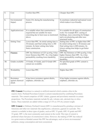
PROPERTIES-
1. Air entrainers [wood-derived acid salts (vinsol resins and wood
rosins) and synthetic resins].
2. Retarders [calcium sulphate or gypsum, Starch, cellulose products,
common sugar, salts of acids].
3. Accelerators [Triethenolamine, calcium formate, silica fume, calcium
chloride, finely divided silica gel etc.].
4. Plasticizers (water reducers) [phthalates, phosphates, carboxylic
acid esters, epoxidized fatty acid esters, polymeric polyesters,
modified polymers; liquid rubbers, and plastics, Nitrile Butadiene
Rubber (NBR), chlorinated PE, EVA, etc.; paraffinic, aromatic].
5. Superplasticizers (High range water reducers) [sulphonated
melamine formaldehyde (SMF), sulphonated naphthalene
formaldehyde (SNF), modified lignosulphonates (MLS) and
polycarboxylate derivatives].
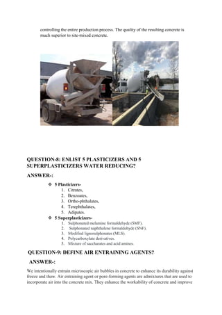
QUESTION-7: SHORT NOTE ON READY MIXED CONCRETE?
ANSWER-:
As the name indicates, Ready Mixed Concrete (RMC) is the concrete which is
delivered in the ready- to-use manner. RMC is defined by the American Concrete
Institute’s Committee 116R-90 as:
"Concrete that is manufactured for delivery to a purchaser in a plastic and unhardened
state".
The Indian Standard Specification IS 4926:2003 defines RMC as:
"Concrete mixed in a stationary mixer in a central batching and mixing plant or in a
truck-mixer and supplied in fresh condition to the purchaser either at the site or into
the purchaser's vehicles".
In India, concrete has traditionally been produced on site with the primitive
equipment’s and use of large labour force. Ready mixed concrete is an advanced
technology, involving a high degree of mechanization and automation. A typical
RMC plant consists of silos and bins for the storage of cement and aggregates
respectively, weigh batchers for proportioning different ingredients of concrete, high
efficiency mixer for thorough mixing of ingredients, and a computerized system](https://image.slidesharecdn.com/constructiontechniques-221018134453-91e31c80/85/CONSTRUCTION-TECHNIQUES-docx-18-320.jpg)