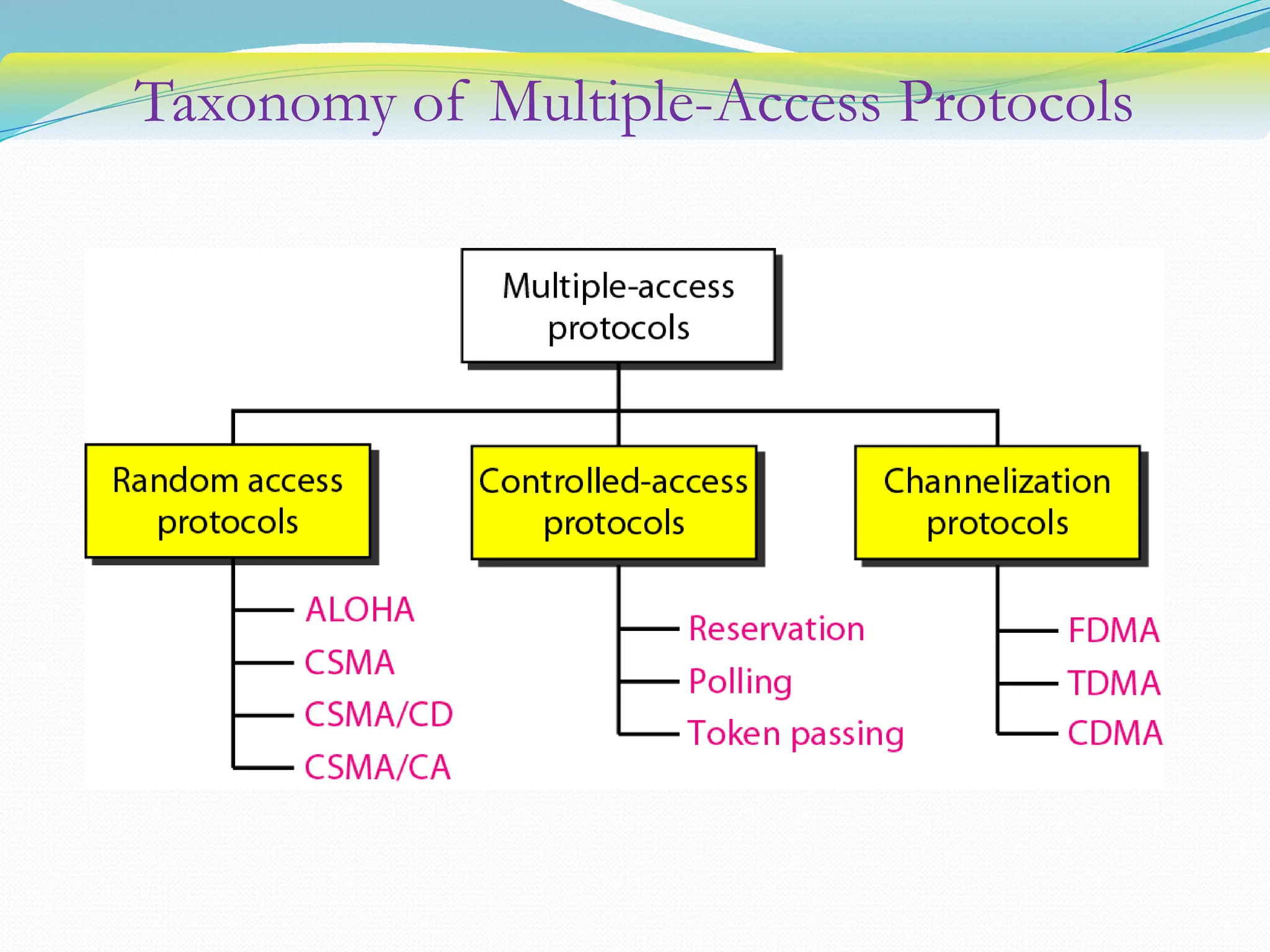
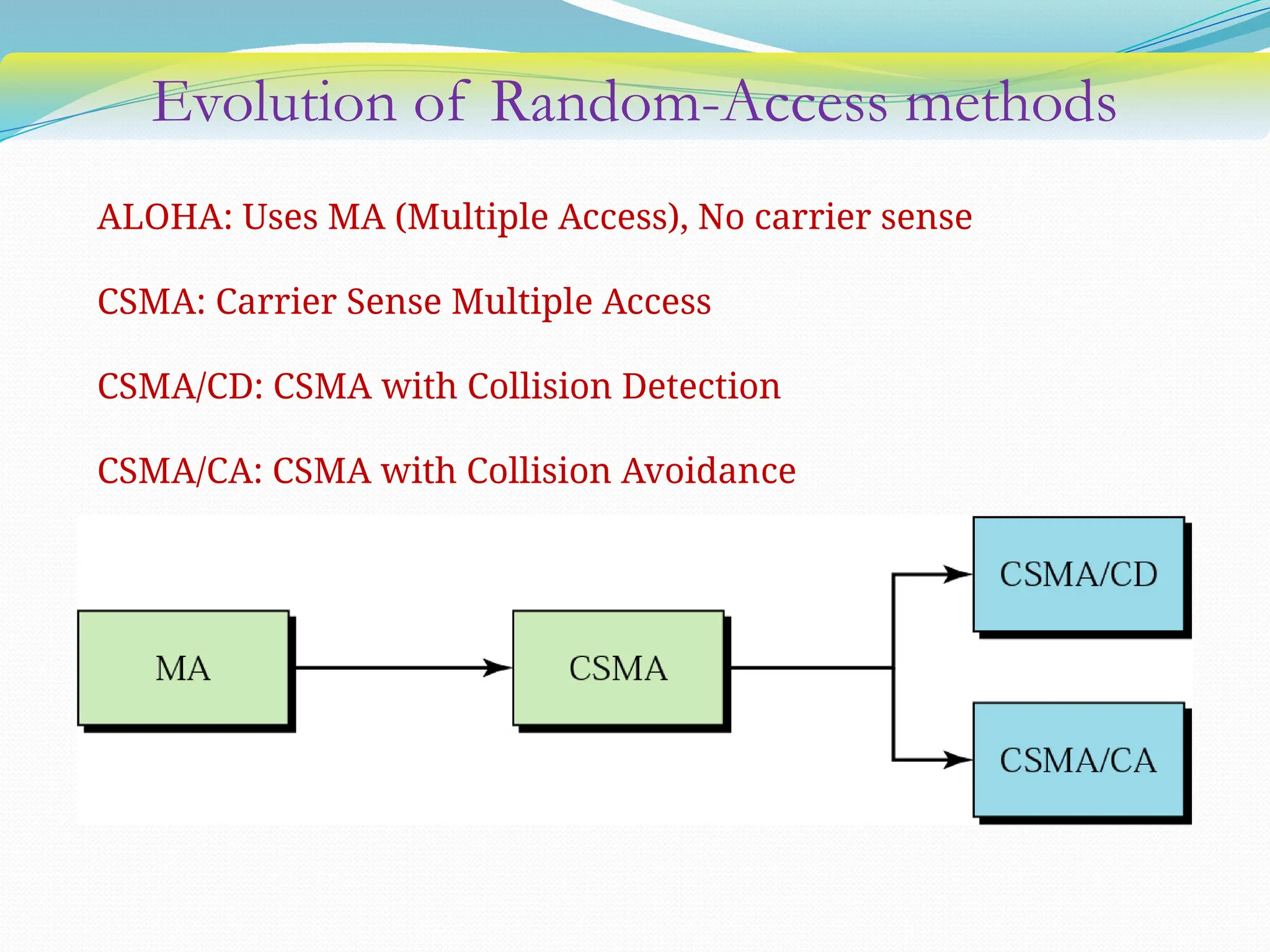
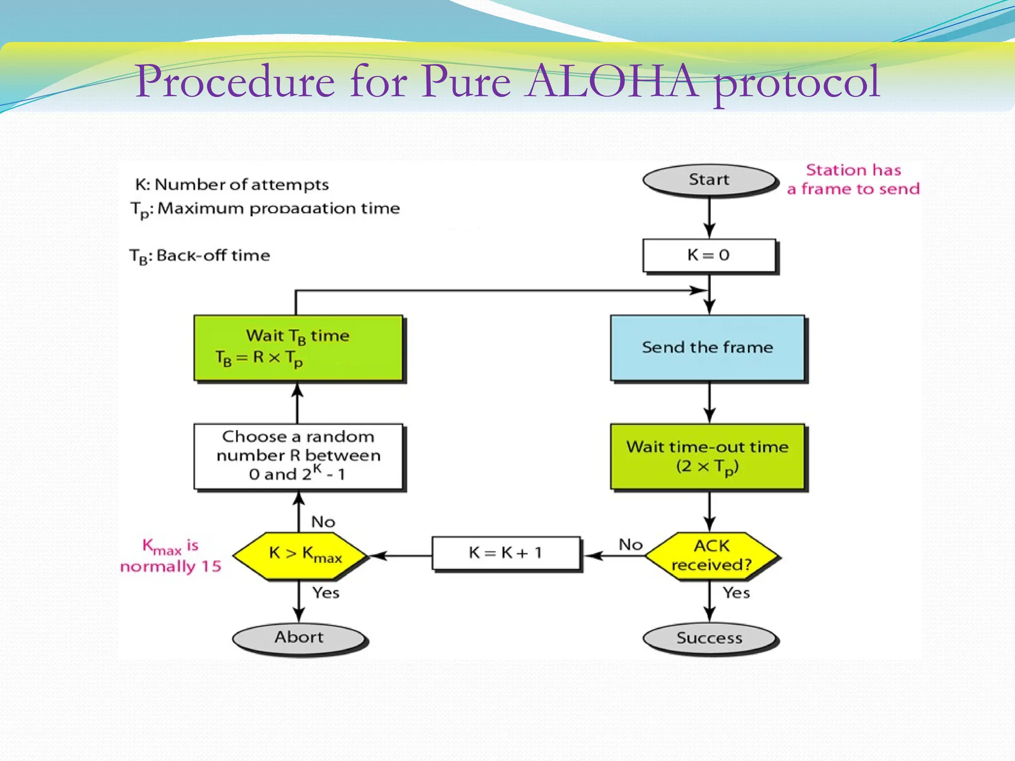
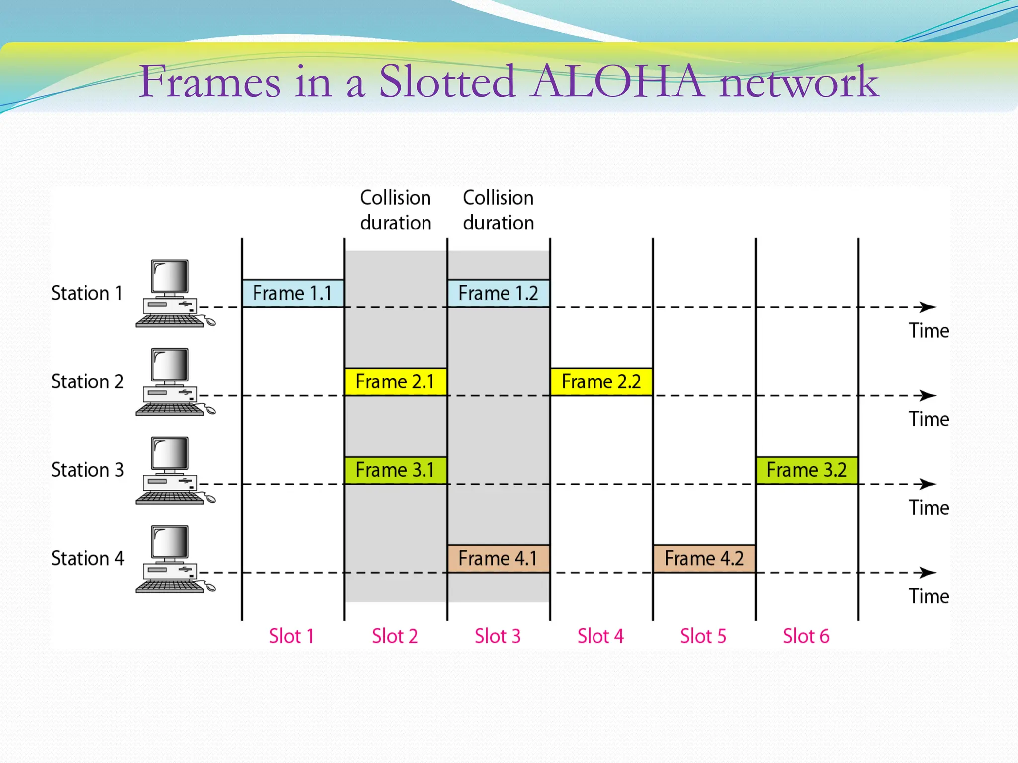
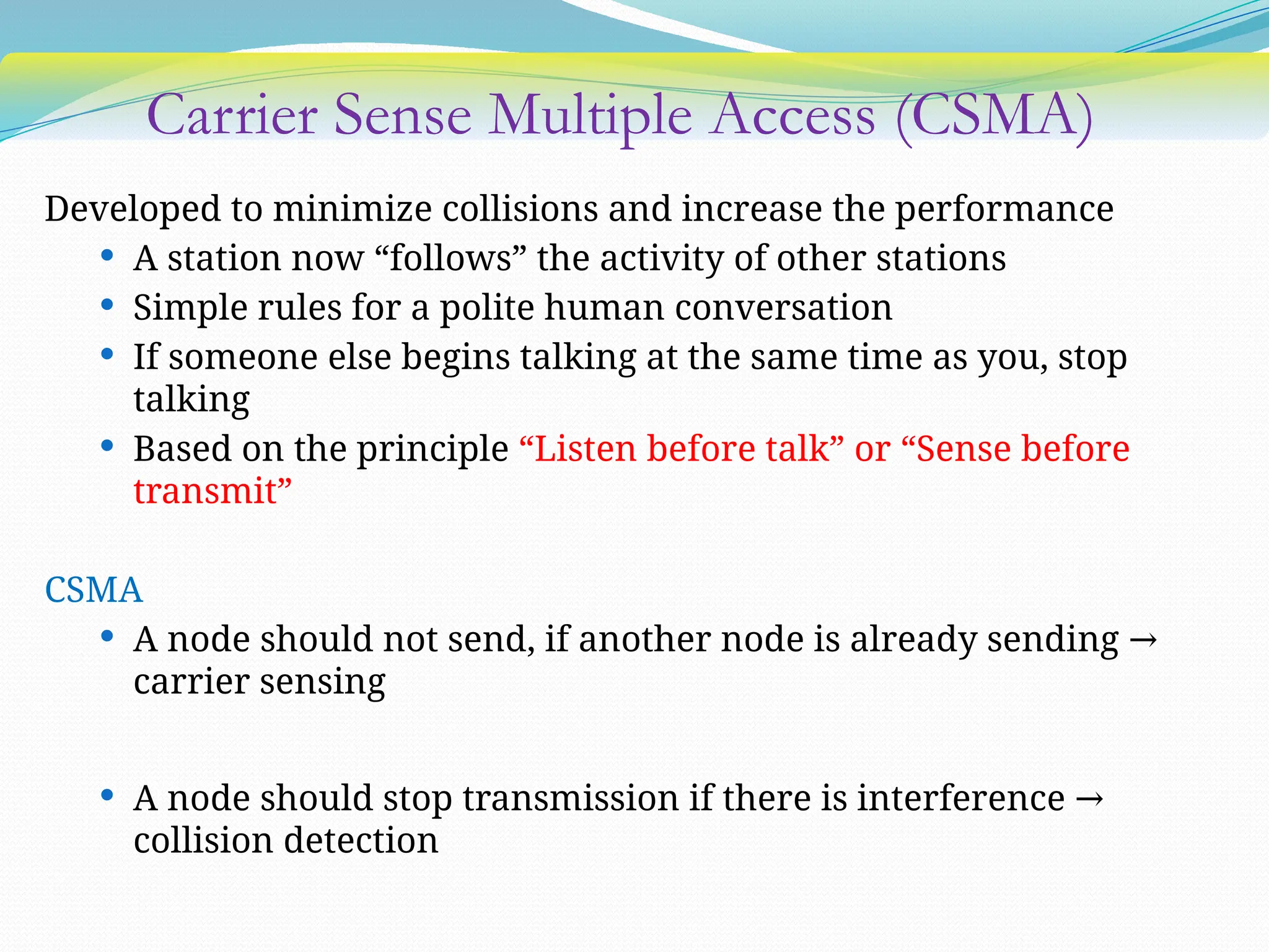
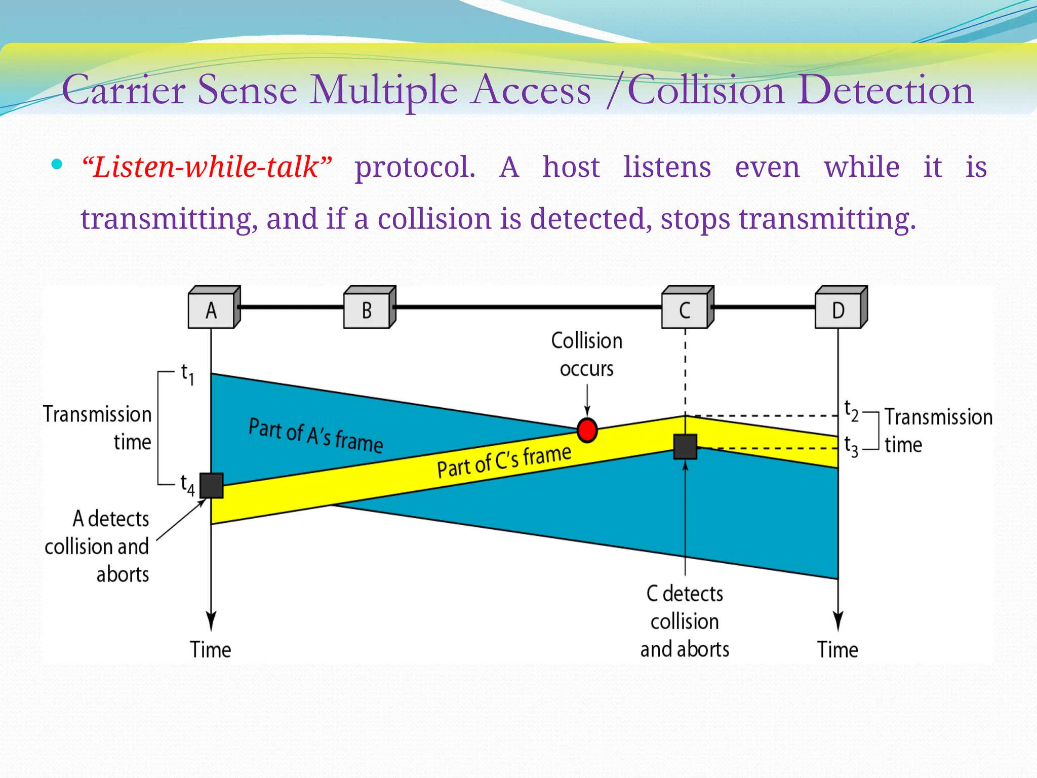
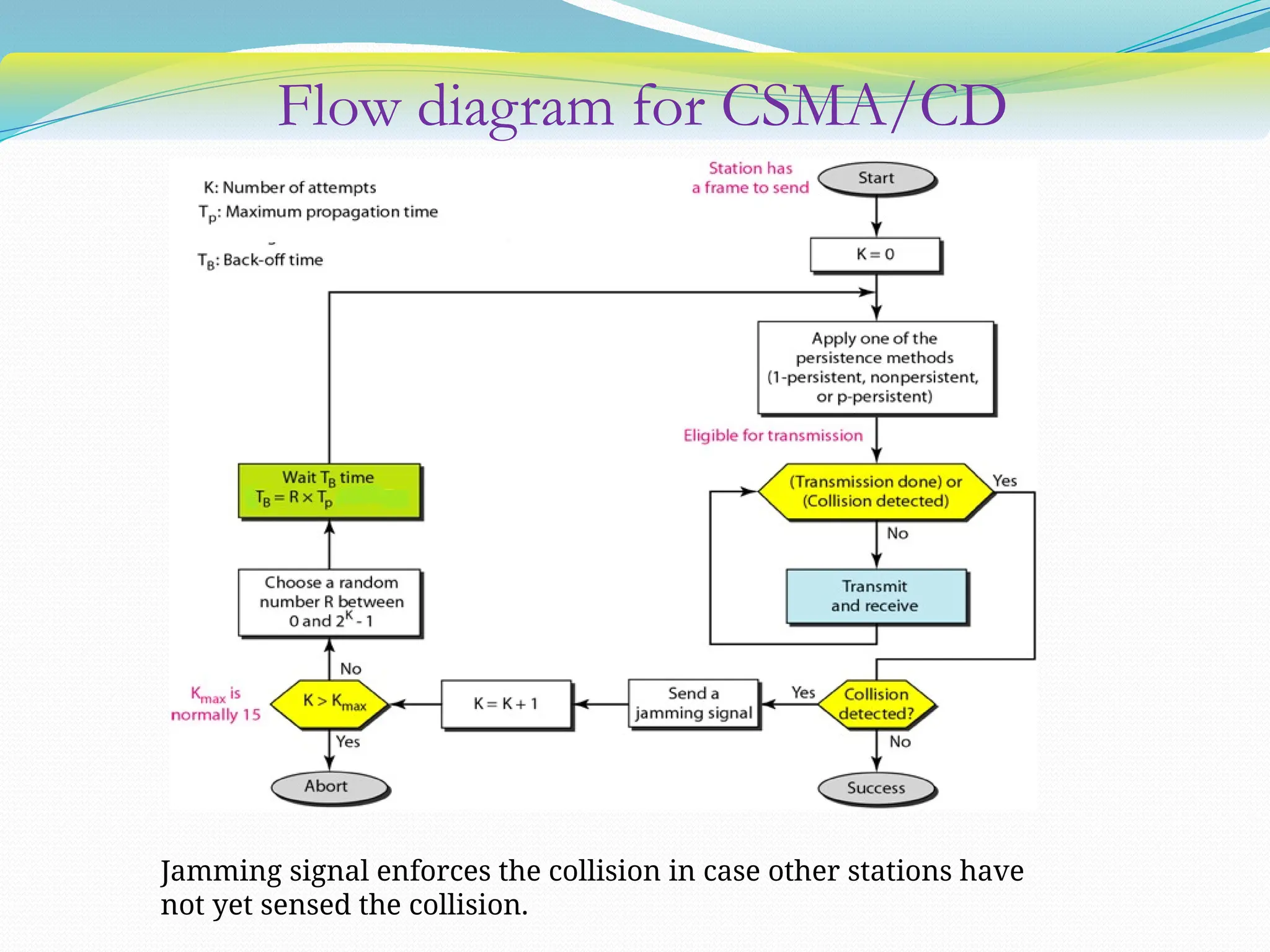
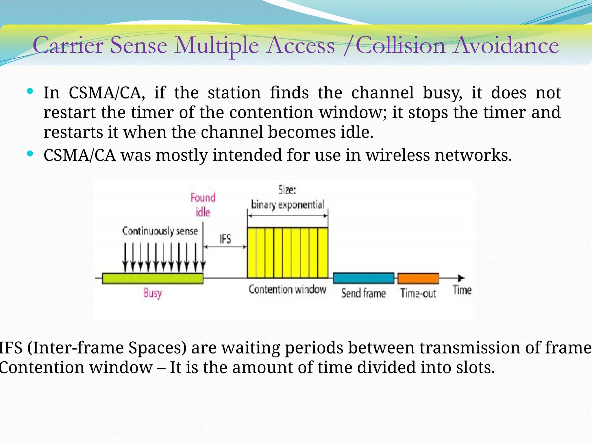
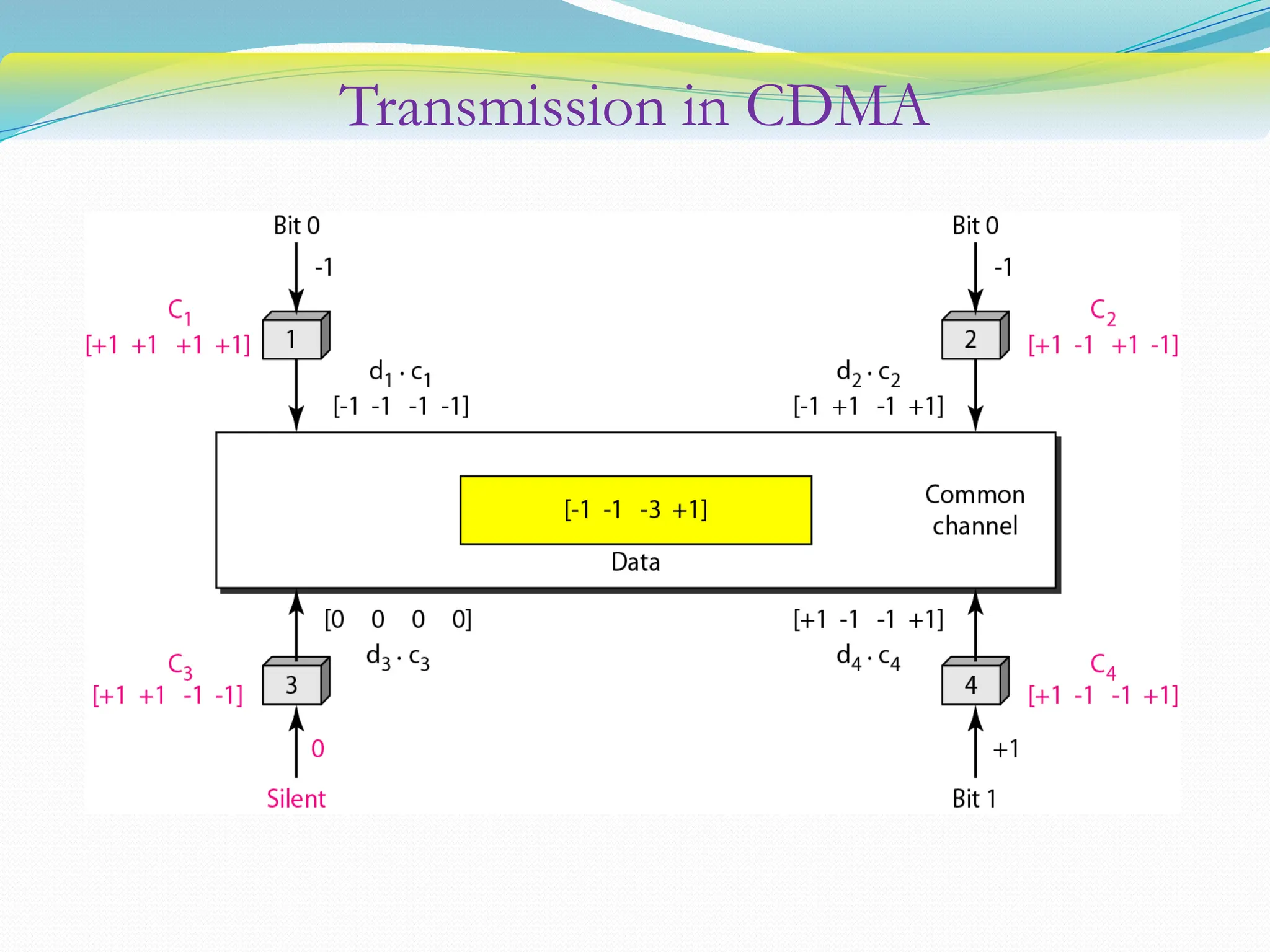
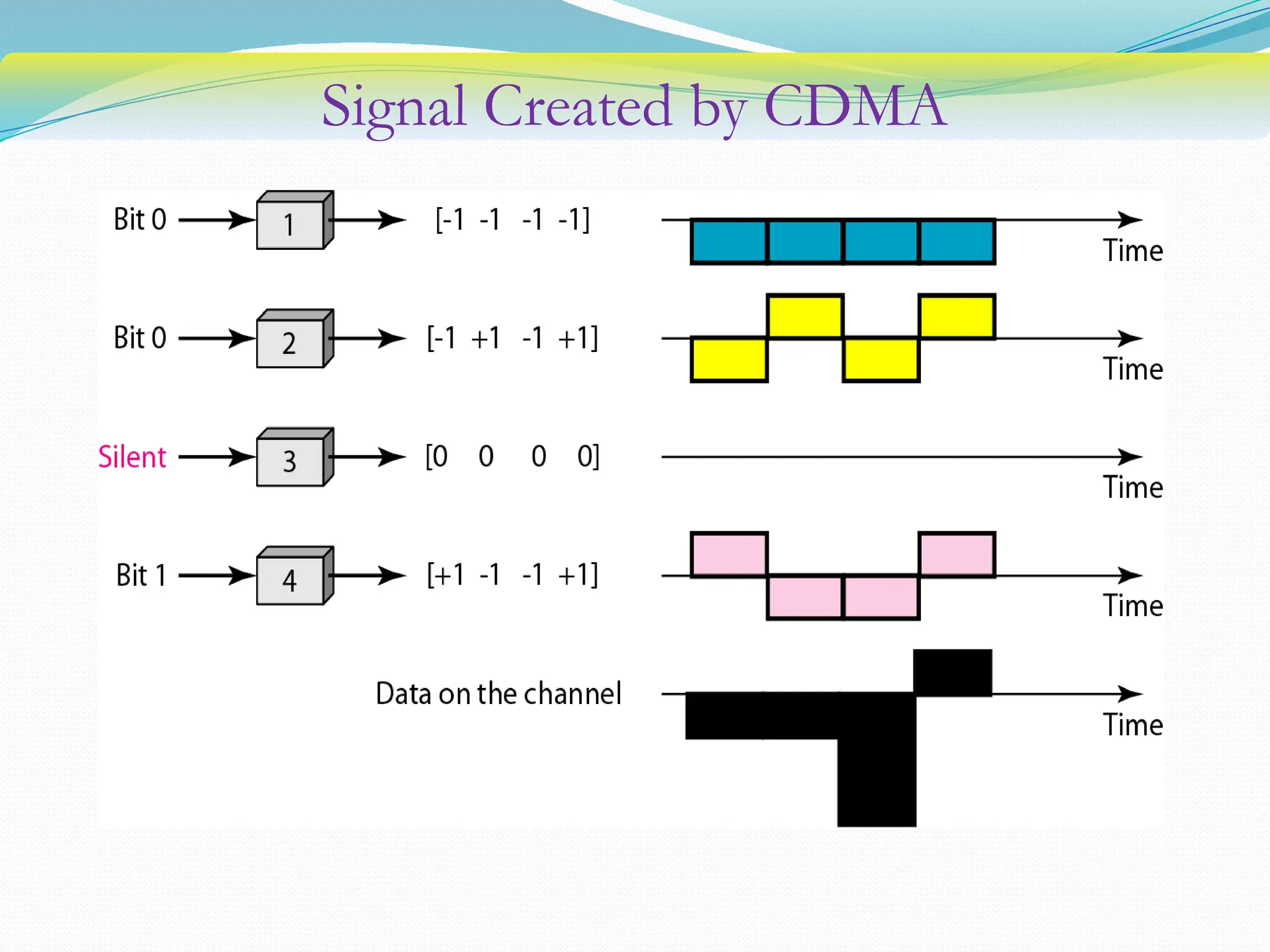
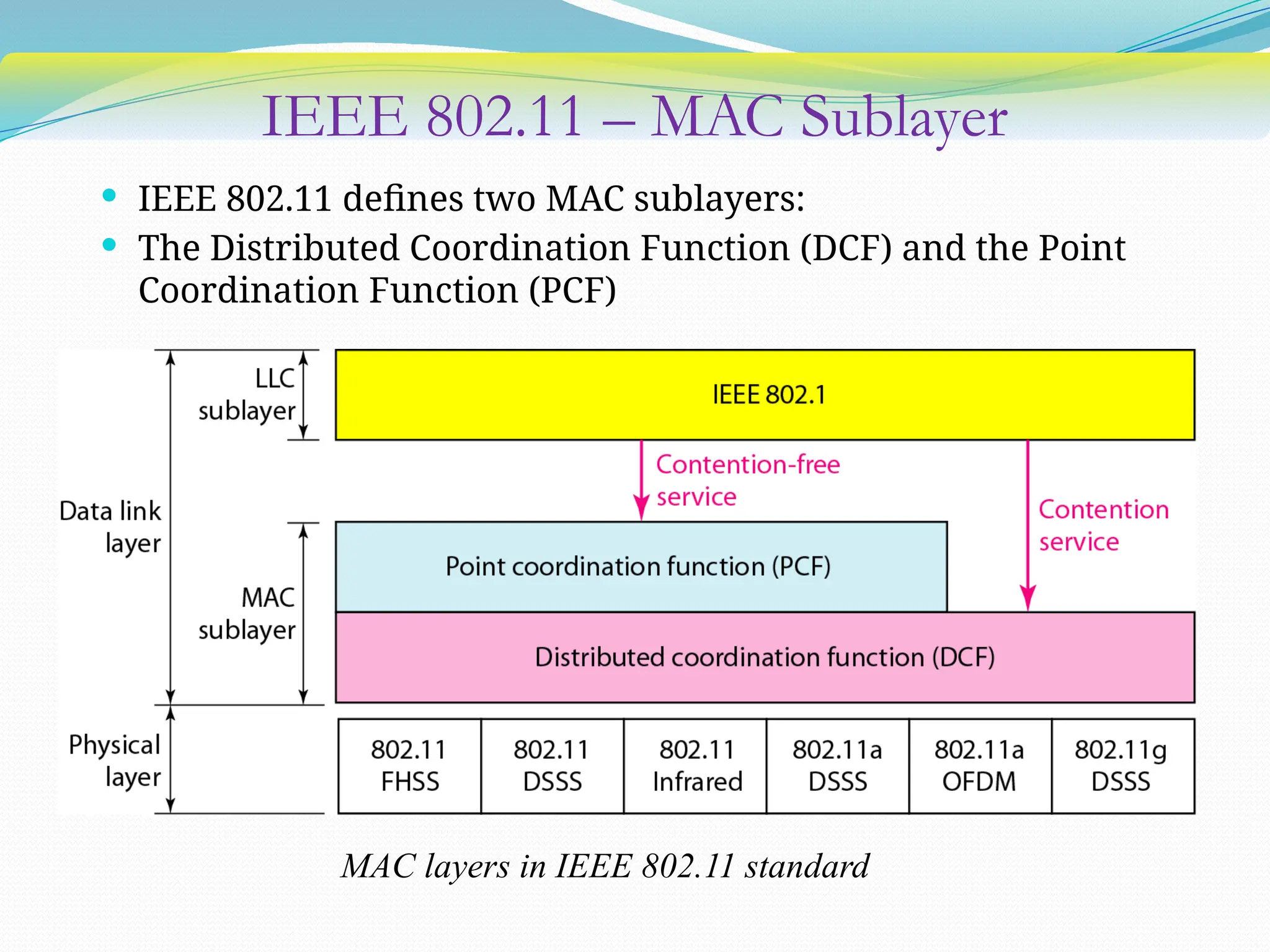
COMPUTER NETWORKS &
SYSTEMS APPROACH
UNIT – III
Media Access Control
Layer
Contents
 Media Access Control
 Wireless LANs
 IEEE 802.11
 ALOHA
 CSMA/CD
 Random Access
 Controlled Access
 Channelization
 Switching
Multiple Access Protocols
 If more than 2 nodes send data at the same time collision
→
 All collided packets are lost waste of bandwidth
→
 We need multiple access protocols to coordinate access to multipoint or
broadcast link.
 Multiple access protocols are needed in LANs, Wi-Fi, and satellite networks
to control the share media.
Human Communication Protocols
Problem of controlling the access to the medium is similar to the
rules of
speaking in an assembly :
 Give everyone a chance to speak
 Raise your hand if you have a question
 Don’t speak until you are spoken to
 Don’t interrupt when someone is speaking
 Don’t monopolize the conversation
 Don’t fall asleep when someone else is talking
MAC Sub layer
 Data link layer is divided into two sub layers: Upper and Lower
 Logical Link Control (LLC): responsible for data link control
(flow and error control)
 Medium Access Control (MAC): resolves the multiple access
to shared media
Taxonomy of Multiple-Access Protocols
Random Access Protocols
 In random access or contention methods, no station is superior to
another station and none is assigned the control over another.
 No station permits another station to send.
 At each instance, a station that has data to send uses a procedure
defined by the protocol to make a decision on whether or not to
send.
 ALOHA
 Carrier Sense Multiple Access (CSMA)
 Carrier Sense Multiple Access with Collision
Detection(CSMA/CD)
 Carrier Sense Multiple Access with Collision Avoidance
Random Access
• Each station has the right to the medium without being controlled
by any other station.
Two features gives the method its name:
• There is no schedule time for a station to transmit:
- transmission is random among stations
• Stations compete with one another to access the medium
- Contention method.
• Collision: An access conflict occurs when more than one station tries
to send, as a result the frame will be either destroyed or modified.
Random Access
 Each station follows a procedure that answer the following
questions to avoid collision:
 When can the station access the medium?
 What can the station do if the medium is busy?
 How can the station determine the success or failure of the
transmission?
 What can the station do if there is an access conflict ?
Evolution of Random-Access methods
ALOHA: Uses MA (Multiple Access), No carrier sense
CSMA: Carrier Sense Multiple Access
CSMA/CD: CSMA with Collision Detection
CSMA/CA: CSMA with Collision Avoidance
Pure ALOHA
 Developed at the University of Hawaii
 Simple method where each station sends a frame whenever it has a
frame to send.
 Since there is only one channel to share, there is the possibility of
collision between frames from different stations.
Frames in a Pure ALOHA network
Pure ALOHA
 It relies on acknowledgments from the receiver. If the ACK dose
not arrive before the time-out period, the station resends the
frame.
 Time-out is equal to the max possible round trip time = 2 x Tp
 Tp (max. propagation time) time required to send a frame between
the most widely separated station.
 To minimize collisions, each station waits a random amount of
time (back-off time TB) before resending its frame.
 TB is a random value that depend on K (the number of attempted
unsuccessful transmissions) .
 After a max. no. of retransmission attempts Kmax, a station must
give up and try later to prevent congestion.
Procedure for Pure ALOHA protocol
Slotted ALOHA
 Slotted ALOHA was invented to improve the efficiency of Pure
ALOHA
 It divides the time into slots of Tfr and force the station to send
only at the beginning of the time slot.
 If the station miss the beginning of synchronized time slot, it must
wait until the beginning of next time slot.
Frames in a Slotted ALOHA network
Carrier Sense Multiple Access (CSMA)
Developed to minimize collisions and increase the performance
 A station now “follows” the activity of other stations
 Simple rules for a polite human conversation
 If someone else begins talking at the same time as you, stop
talking
 Based on the principle “Listen before talk” or “Sense before
transmit”
CSMA
 A node should not send, if another node is already sending →
carrier sensing
 A node should stop transmission if there is interference →
collision detection
CSMA
 Sense the carrier before transmit : “listen before you talk”
 CSMA can reduce the possibility of collision, but it can not
eliminate it because of the propagation delay (a station may
sense the medium and find it idle, only because the first bit of
a frame sent by another station has not been received).
Space/Time model of collision of CSMA
C
B
Vulnerable time in CSMA
 Vulnerable time: Time in which there is a possibility of collision.
 Vulnerable time for CSMA is the max propagation time, Tp needed
for a signal to propagate from one end of the medium to the other.
 When a station sends a frame, and any other station tries to send
during this time it leads to collision.
 But if the first bit of frame reaches the end of medium, every other
station will already have heard the bit and will refrain from
sending.
Types of CSMA Protocols
• Different CSMA protocols determine:
- What should a station do if the channel is busy?
- What should a station do if the channel is idle?
1. 1-persistence method
2. Non-persistence method
3. P-persistence method
1-persistence method
 To avoid idle channel time, 1-persistent protocol is used
 Station wishing to transmit listens to the medium:
 If medium is idle, transmit immediately;
 If medium is busy, continuously listen until medium
becomes idle & then transmit immediately with probability 1
 Performance
 1-persistent stations are selfish
 If two or more stations becomes ready at the same time,
collision guaranteed
***Chance of collision is high
Non-persistence method
 A station with frames to be sent, should sense the medium
1. If medium is idle, transmit
2. If medium is busy, (backoff) wait a random amount of time and
repeat 1
 Non-persistent stations are deferential (respect others)
 Performance:
 Random delays reduces probability of collisions because two
stations with data to be transmitted will wait for different amount
of times.
 Bandwidth is wasted, if waiting time (backoff) is large because
medium will remain idle following end of transmission even if one
or more stations have frames to send.
P-persistence method
 Time is divided into slots where
each time slot typically equals
maximum propagation time.
 Station wishing to transmit
listens to the medium:
1. If medium is idle,
 transmit with probability (p),
OR
 wait one time slot with
probability (1 – p), then repeat
1.
2. If medium is busy, continuously
listen until idle and repeat step 1
 Performance:
 Reduces the possibility of
collisions like non-persistent.
 Reduces channel idle time like
1-persistent.
CSMA/CD Protocol
 CSMA (all previous methods) has an inefficiency:
 If a collision has occurred, the channel is unstable until colliding
packets have been fully transmitted.
 CSMA/CD (Carrier Sense Multiple Access with Collision Detection)
overcomes this as follows:
 While transmitting, the sender is listening to medium for
collisions.
 Sender stops transmission if collision has occurred, reducing
channel wastage.
Carrier Sense Multiple Access /Collision Detection
 “Listen-while-talk” protocol. A host listens even while it is
transmitting, and if a collision is detected, stops transmitting.
Carrier Sense Multiple Access /Collision Detection
 Use one of the CSMA persistence algorithm (non-persistent, 1-
persistent, p-persistent) for transmission.
 If a collision is detected by a station during its transmission then
it should do the following:
- Abort transmission and
- Transmit a jam signal (48 bit) to notify other stations of
collision so that they will discard the transmitted frame also to
make sure that the collision signal will stay until detected by
the farthest station.
- After sending the jam signal, back off (wait) for a random
amount of time, then
- Transmit the frame again.
Flow diagram for CSMA/CD
Jamming signal enforces the collision in case other stations have
not yet sensed the collision.
Collision Detection
 How the station detects a collision?
 Detecting voltage level on the line
 Detecting energy level
 Detecting simultaneous transmissions and receptions
 Energy in channel can have three values: zero, normal, and
abnormal.
 At zero level, the channel is idle.
 At the normal level, a station has successfully captured the channel
and is sending its frame.
 At the abnormal level, there is a collision and the level of the
energy is twice the normal level.
Carrier Sense Multiple Access /Collision Avoidance
 In CSMA/CA, if the station finds the channel busy, it does not
restart the timer of the contention window; it stops the timer and
restarts it when the channel becomes idle.
 CSMA/CA was mostly intended for use in wireless networks.
IFS (Inter-frame Spaces) are waiting periods between transmission of frame
Contention window – It is the amount of time divided into slots.
Flow diagram for CSMA/CA
Contention
window size is 2K
-
1
After each slot:
- If idle, continue
- If busy, stop and
continue when idle
Controlled Access
 In controlled access, the stations consult one another to find which
station has the right to send.
 A station cannot send unless it has been authorized by other
stations.
 Provides in order access to shared medium so that every station has
chance to transfer (fair protocol).
 Eliminates collision completely.
 Controlled Access methods
 Reservation
 Polling
 Token Passing
Reservation Access Method
 A station needs to make a reservation before sending data
 Time is divided into intervals
 A reservation frame precedes each time interval
 Number of stations and number of mini-slots in the reservation
frame are equal
 Each time slot belongs to a particular station
 If there are N stations in the system, there are exactly N mini-slots
in the reservation frame
Polling Access Method
 Devices are designated as a Primary station and Secondary station
 All data exchange must go through the primary station
 Primary station controls the link and initiates the session; the
secondary station follow its instructions
Two functions: Poll and Select
 Poll: If the primary wants to receive data, it asks the secondary if
they have anything to send
 Select: If the primary wants to send data, it tells the secondary to
get ready to receive data
Select function
• The Select function is
used when the primary
has frames to send
• The primary creates and
transmits a select (SEL)
frame
• SEL alerts the secondary
for the upcoming
transmission
• The primary waits for
ACK to send the data
Poll function
 When the primary is ready to
receive data, it must ask Poll
signal to each device in turn if it
has anything to send.
 When the first secondary is
approached, it responds either
with a NAK frame if it has
nothing to send or with data if it
does.
 If the response is NAK, the
primary Polls the next
secondary.
 If it receives data, it sends ACK
frame.
Token Passing
 In the Token-Passing, the stations are organized in a logical ring
 For each station there is a predecessor and a successor
 Predecessor is the station which is logically before the station in
the ring
 Successor is the station which is logically after the station in the
ring
 Current station is the one that is accessing the channel currently
 How is the right to access the channel passed from one station to
another?
Token Passing (Contd.)
 Station is authorized to send data when it receives a special packet
called a token.
 Stations are arranged around a ring.
 When no data is being sent, a token circulates the ring.
 If a station needs to send data, it waits for the token.
 The station captures the token and sends one or more frames (as
long as it has frames to send or the allocated time has not
expired), and finally it releases the token to be used by next
station (successor).
 The maximum time any station can hold the token is limited.
 Since there is only one token, only one station transmits at a time,
and collisions never occur.
Token Passing (Contd.)
Token management is needed for this access method:
 Stations must be limited in the time they can have possession of
the token.
 The token must be monitored to ensure it has not been lost or
destroyed (if the station that is holding the token fails, the token
will disappear from the network).
 Assign priorities to the stations, to make low-priority stations
release the token to high priority stations.
 Stations do not have to be physically connected in a ring; the ring
can be a logical one.
Token-Passing Procedure
Logical ring and Physical topology in Token-Passing
access method
Channelization
 Channelization is a multiple access method in which the
available bandwidth of a link is shared in time, frequency or
through code, between different stations.
 Three methods:
 Frequency Division Multiple Access (FDMA)
 Available bandwidth of the common channel is divided into
bands that are separated by guard bands
 Time Division Multiple Access (TDMA)
 The bandwidth is just one channel that is timeshared
between different stations
 Code Division Multiple Access (CDMA)
 One channel carries all transmissions simultaneously
Frequency Division Multiple Access (FDMA)
 In FDMA, the available bandwidth is divided into frequency
bands.
 Each station is allocated a band to send its data.
 To prevent station interferences, the allocated bands are
separated from one another by small guard bands.
Time Division Multiple Access (TDMA)
 In TDMA, the stations share the bandwidth of the channel in
time.
 Each station is allocated a time slot during which it can send
date.
 Achieving synchronization between different stations is the
main problem. This can be achieved by introducing sync bits
at the beginning of each slot.
 The concept of guard times is present in TDMA.
Code Division Multiple Access (CDMA)
 In CDMA, one channel occupies the entire bandwidth of the
link.
 In CDMA, one channel carries all transmissions at the same
time.
 Consider the idea
• Let us assume, we have 4 stations 1, 2, 3, & 4 connected to
same channel. The data from station 1 is d1, from station 2 is
d2, & so on. The code assigned to the station 1 is c1, to the
station 2 is c2, & so on.
• We assume that the assigned codes have two properties:
1. If we multiply each code by another, we get 0.
2. If we multiply each code by itself, we get 4 (i.e., the no. of
stations)
 With the above two properties taken into consideration,
let us see how the 4 stations can send data using the
Simple idea of communication with code
 Any station that wants to receive data from one of the other 3
stations, it multiplies the data on the channel by the code of the
sender.
 For example, stations 3 and 4 are talking to each other. Station 4
wants to hear what station 3 is saying. It multiplies the data on
the channel by c3.
 Data = (d1 c
⋅ 1 + d2 c
⋅ 2 + d3 c
⋅ 3 + d4 c
⋅ 4) c
⋅ 3
= d1 c
⋅ 1 c
⋅ 3 + d2 c
⋅ 2 c
⋅ 3 + d3 c
⋅ 3 c
⋅ 3 +d4 c
⋅ 4 c
⋅ 3
= 4 × d3
Chip Sequences
 Each station is assigned a unique chip sequence
 Chip sequences are orthogonal sequences
 Inner product of any pair must be zero
 With N stations, sequences must have the following
properties:
 They are of length N
 Their self inner product is always N
 Data Representation
Transmission in CDMA
CDMA Encoding
Signal Created by CDMA
CDMA Decoding
IEEE 802.11 Wireless LAN Standard
• In response to lacking standards, IEEE developed the first
internationally recognized wireless LAN standard – IEEE
802.11
• IEEE published 802.11 in 1997, after seven years of work
• Scope of IEEE 802.11 is limited to Physical and Data Link
Layers
• Benefits:
 Appliance Interoperability
 Fast Product Development
 Stable Future Migration
 Price Reductions
 The 802.11 standard takes into account the following
significant differences between wireless and wired LANs:
Power Management
Security
Bandwidth
IEEE 802.11 Terminology
 Access Point (AP): A station that provides access to the DS.
 Basic Service Set (BSS): An ad-hoc self-contained network with
station-to-station traffic flowing directly, receiving data
transmitted by another station, and only filtering traffic based on
the MAC address of the receiver.
 A set of stationary or mobile wireless stations and an optional
central base station, known as the access point (AP).
 Distribution System (DS): A system used to interconnect a set of
BSSs to create an ESS.
 DS is implementation-independent. It can be a wired 802.3
Ethernet LAN, 802.4 token bus, 802.5 token ring or another
802.11 medium.
 Extended Service Set (ESS):Two or more BSS interconnected by DS
 Extended service set uses two types of stations: mobile and
stationary.
 The mobile stations are normal stations inside a BSS. The
stationary stations are AP stations that are part of a wired LAN.
IEEE 802.11 – MAC Sublayer
 IEEE 802.11 defines two MAC sublayers:
 The Distributed Coordination Function (DCF) and the Point
Coordination Function (PCF)
MAC layers in IEEE 802.11 standard
Distributed Coordination Function (DCF)
 It is one of the 2 protocols defined by IEEE at MAC sublayer.
 DCF uses CSMA/CA.
 Wireless LANs cannot implement CSMA/CD because it is a
costly affair and due to increased bandwidth requirements.
CSMA/CA and NAV
DIFS – Distributed Interframe Space
RTS – Request To Send
SIFS – Short Interframe Space
CTS – Clear To Send
NAV – Network Allocation Vector
Point Coordination Function (PCF)
 The Point Coordination Function (PCF) is an optional access
method that can be implemented in an infrastructure
network.
 It is implemented on top of the DCF and is mostly for time-
sensitive transmission.
 PCF has a centralized, contention-free polling access method.
 The Access Point (AP) performs polling for stations that are
capable of being polled. The stations are polled one after
another, sending any data they have to the AP.
Frame Format
The MAC layer frame consists of nine fields.
Frame Control (FC): The FC field is 2 bytes long and defines the type of
frame and some control information.
Subfields in FC field
Frame Format (Contd.)
 D (Duration):
 In all frames types (except in one type), this field defines the
value of Network Allocation Vector (NAV).
 In one control frame only, this field defines the ID of the
frame.
 Addresses:
 There are 4 address fields, each 6 bytes long.
 The meaning of each address field depends on the value of
To DS and From DS subfields.
 Sequence Control:
 This field defines the sequence number of the frame to be
used in flow control.
Frame Format (Contd.)
 Frame body:
 This field, which ranges between 0 and 2312 bytes, contains
information based on the type and the subtype defined in the
FC field.
 FCS:
 The FCS field is 4 bytes long and contains a CRC-32 error
detection sequence.
Frame Types
 IEEE 802.11 has 3 categories of frames: Management frames,
Control frames, Data frames.
 Management frames: Management frames are used for the
initial communication between stations and access points.
 Control frames: Control frames are used for accessing the
channel and acknowledging frames.
Values of subfields in
control frames
Data Frames: Data frames are used for carrying data and control
information.
Switched Network
 With a large number of end systems it is not practical to connect
each pair.
 In large networks, we need some means to allow one-to-one
communication between any two nodes.
 In LANs, this is achieved using one of three methods:
 Direct point-to-point connection (mesh)
 Via central controller (star)
 Connection to common bus in a multipoint configuration
(bus/hub)
 These are ruled out for large networks either because of the
increased distance or devices.
 The solution is a SWITCHED NETWORK.
 Consists of a series of interlinked nodes called SWITCHES.
 Switches are devices capable of creating temporary
connections between two or more devices linked to the
switch.
Switched Network
Switched Networks
Circuit Switched Network
 A circuit-switched network consists of a set of switches connected
by physical links.
 A connection between two stations is a dedicated path made of
one or more links. The dedicated path is called a circuit-switched
connection or circuit.
 Each link is normally divided into
‘n’ channels by using FDM or TDM.
 Each connection uses only one
dedicated channel on each link.
 The link can be permanent (leased
line) or temporary (telephone).
 Circuit switching takes place at PHYSICAL LAYER.
 Reservation of resources must be made during set up phase that
remains dedicated for the entire duration of data transfer until
tear down phase.
 Such as bandwidth in FDM and time slot in TDM.
 Data transferred is not packetized, but it is a continuous flow.
 No addressing is involved during data transfer. Switches route
the data based on the occupied band (FDM) or time slot (TDM).
Circuit Switched Network
Circuit Switch: Phases
3 phase management:
 Setup phase:

A setup request moves from sender to receiver that includes the
address of the destination to the nearest switch. This switch finds
a channel between itself and the switch close to the destination

An acknowledgment packet is returned from destination and
then connection is established.
 Data transfer phase:
 Two parties can transfer data.
 Tear-down phase:

When the last of the data arrives at the destination, the tear-
down begins where the resources are released.
 “Busy Signal” if capacity for a circuit not available.
Circuit Switch - Telephone call between two users
Delay in a circuit-switched network
 Once the connection is established, there is minimal delay for
data between the stations.
 A dedicated path exists between sender and receiver.
Advantages and Disadvantages
 Delay in this type of network is minimal.
o Circuit switched networks are not as efficient as the other two
networks because
o Resources are allocated during entire session of connection
that are unavailable to other connections.
Datagram Networks
 Messages sent through packet switched network are divided into
packets of fixed or variable size. The size depends on the protocol
and network.
 Datagram networks are referred to as connectionless (switch has
no information about the connection state). A device known as a
Router (L-3 switch) creates a connectionless network.
 Connectionless implies that the path between sender and receiver
is not dedicated. Hence no resource allocation (bandwidth,
processing time). Resources are allocated on demand, i.e., on FCFS.
 Datagram switching is done at NETWORK LAYER. No setup or
tear down phases. Header Data Trailer
Datagram's
 A single message is divided into datagram's (packet) and
individual datagram's are not treated as a single stream of
data even if they belong to the same message.
 Datagram's from one message can take different paths to the
destination and can arrive out of order.
 Switch (Routers) in a datagram network uses a database
(routing table) that is based on destination address. The
routing table directs the datagram's towards the final
destination.
Datagram network with four routers
• All packets belong to the
message from same source
but travel in different paths
to reach destination either
because the links involved
are busy carrying packets
from other sources or
because of lack of
necessary bandwidth.
• This causes packets to
arrive out of order with
different delays.
• Packets may also be
dropped or lost because of
lack of resources.
Routing table in a datagram network
 Each router has a routing table which is based on the
destination address.
 Routing tables are dynamic and are updated periodically.
Destination address and corresponding forwarding output
ports are recorded in the table.
 The destination address in the header of a packet in a
datagram network remains the same during the entire
journey of the packet.
 When router receives the packet, destination address is
examined. Routing table is consulted to find the
corresponding port through which packet should be
forwarded.
 Efficiency is better than circuit switching and greater delay
compared to virtual network.
Virtual Circuit Network
 VCN is a combination of a datagram and circuit network that is
implemented at the DATA LINK LAYER. It has some
characteristics of both.
 As in circuit switched network it involves 3 phases for the
transmission to take place.
 VC setup and acknowledgement
- Switch creates an entry for a virtual circuit using their
addresses
 Data transfer
 Tear-down
- Source and destination inform the switches to delete the
corresponding entry
 Resources can be allocated during setup phase, as in circuit
network or on demand, as in datagram network.
 Data is transferred as packets and all are sent along a pre-
established path (virtual circuit).
Virtual Circuit Network
• The network has switches that allow traffic from sources to
destinations.
• Source or destination can be packet switch, bridge or any
other device that connects other networks.
 In VCN, two types of addressing are involved:
 Global – unique in the scope of network and is used only to create VCI.
 Virtual circuit identifier – small number used for the data transfer and has only
switch scope. Every packet contain address information (VCI), which is not host
destination address.
 In VC networks, the route is setup in the connection establishment phase. During the
setup, source and destination use global address to help switches make table entries
for connection. Each router assigns a VC number (VC#) to the virtual circuit that can
be different for each hop & is written into the packet headers. In tear down phase
switches are informed to delete the corresponding entries.
 Each VC occupies routing table entries. When a frame arrives at a switch it has one
VCI and when it leaves it has different VCI.
 The VCI directs the datagram towards its
final destination.
Virtual Circuit Network
Switch and tables in a virtual-circuit network
Set up request in VCN
Setup Frame
 “A” sends setup frame to switch 1.
 Switch 1 receives the request and gets to know that it should go
out through Port 3 and creates an entry for this virtual circuit. It
fills only three of the four columns and the outgoing VCI will be
found during the acknowledgement step.
 It then forwards to switch 2 and the same events happen here as
at switch 1. In this case, incoming port(1), incoming VCI(66) and
outgoing port(2)
 Switch 3 also receives setup request and the same process
continues
 Now, “B” receives setup frame and if it is ready to receive frames
Set up Acknowledgement in VCN
Acknowledgement Frame
 Acknowledgement frame completes the entries in the switch table.
 Acknowledgement from B to switch 3 carries global source and
destination address so the switch knows which entry in the table is
to be completed. It also carries VCI 77 chosen by the destination as
the incoming VCI for frames from A.
 Switch 3 sends ACK to switch 2 that contains its incoming VCI and
switch 2 sends ACK to switch 1 that contains its incoming VCI.
 Finally switch 1 sends an acknowledgement to source A that
contains its incoming VCI.
Data transfer and Tear down process
After sending all frames, a special frame called Tear Down Request is
sent to end the connection. “B” responds with a tear down
confirmation frame. All switches delete the corresponding entry from
their tables.
Delay in a Virtual Circuit Network
Total Delay – Setup delay + Tear down delay + Propagation
time +
Transmission time
If resources allocated during setup, no wait time for packets.
Advantages and Disadvantages
 Resource reservation can be made during the setup or can be
made on demand during data transfer phase.
 In VCN, all the packets that belong to the same source and
destination travel the same path, but packet may arrive at the
destination with different delays if resource allocation is on
demand.
Comparison
 Dedicated
transmission path
 Continuous
transmission
 Path stays fixed for
entire connection
 Call setup delay
 Negligible
transmission delay
 No queuing delay
 Busy signal
overloaded network
 Fixed bandwidth for
each circuit
 No overhead after
call setup
Circuit Switching
 No dedicated
transmission path
 Transmission of
packets
 Route of each
packet is
independent
 No setup delay
 Transmission delay
for each packet
 Queueing delays at
switches
 Delays increase in
overloaded
networks
 Bandwidth is
shared by all
packets
 Overhead in each
packet
Datagram Packet
Switching
 No dedicated
transmission path
 Transmission of
packets
 Path stays fixed for
entire connection
 Call setup delay
 Transmission delay
for each packet
 Queueing delays at
switches
 Delays increase in
overloaded
networks
 Bandwidth is
shared by all
packets
 Overhead in each
packet
VC Packet
Switching

computer__networks .pptx

  • 1.
    COMPUTER NETWORKS & SYSTEMSAPPROACH UNIT – III Media Access Control Layer
  • 2.
    Contents  Media AccessControl  Wireless LANs  IEEE 802.11  ALOHA  CSMA/CD  Random Access  Controlled Access  Channelization  Switching
  • 3.
    Multiple Access Protocols If more than 2 nodes send data at the same time collision →  All collided packets are lost waste of bandwidth →  We need multiple access protocols to coordinate access to multipoint or broadcast link.  Multiple access protocols are needed in LANs, Wi-Fi, and satellite networks to control the share media.
  • 4.
    Human Communication Protocols Problemof controlling the access to the medium is similar to the rules of speaking in an assembly :  Give everyone a chance to speak  Raise your hand if you have a question  Don’t speak until you are spoken to  Don’t interrupt when someone is speaking  Don’t monopolize the conversation  Don’t fall asleep when someone else is talking
  • 5.
    MAC Sub layer Data link layer is divided into two sub layers: Upper and Lower  Logical Link Control (LLC): responsible for data link control (flow and error control)  Medium Access Control (MAC): resolves the multiple access to shared media
  • 6.
  • 7.
    Random Access Protocols In random access or contention methods, no station is superior to another station and none is assigned the control over another.  No station permits another station to send.  At each instance, a station that has data to send uses a procedure defined by the protocol to make a decision on whether or not to send.  ALOHA  Carrier Sense Multiple Access (CSMA)  Carrier Sense Multiple Access with Collision Detection(CSMA/CD)  Carrier Sense Multiple Access with Collision Avoidance
  • 8.
    Random Access • Eachstation has the right to the medium without being controlled by any other station. Two features gives the method its name: • There is no schedule time for a station to transmit: - transmission is random among stations • Stations compete with one another to access the medium - Contention method. • Collision: An access conflict occurs when more than one station tries to send, as a result the frame will be either destroyed or modified.
  • 9.
    Random Access  Eachstation follows a procedure that answer the following questions to avoid collision:  When can the station access the medium?  What can the station do if the medium is busy?  How can the station determine the success or failure of the transmission?  What can the station do if there is an access conflict ?
  • 10.
    Evolution of Random-Accessmethods ALOHA: Uses MA (Multiple Access), No carrier sense CSMA: Carrier Sense Multiple Access CSMA/CD: CSMA with Collision Detection CSMA/CA: CSMA with Collision Avoidance
  • 11.
    Pure ALOHA  Developedat the University of Hawaii  Simple method where each station sends a frame whenever it has a frame to send.  Since there is only one channel to share, there is the possibility of collision between frames from different stations.
  • 12.
    Frames in aPure ALOHA network
  • 13.
    Pure ALOHA  Itrelies on acknowledgments from the receiver. If the ACK dose not arrive before the time-out period, the station resends the frame.  Time-out is equal to the max possible round trip time = 2 x Tp  Tp (max. propagation time) time required to send a frame between the most widely separated station.  To minimize collisions, each station waits a random amount of time (back-off time TB) before resending its frame.  TB is a random value that depend on K (the number of attempted unsuccessful transmissions) .  After a max. no. of retransmission attempts Kmax, a station must give up and try later to prevent congestion.
  • 14.
    Procedure for PureALOHA protocol
  • 15.
    Slotted ALOHA  SlottedALOHA was invented to improve the efficiency of Pure ALOHA  It divides the time into slots of Tfr and force the station to send only at the beginning of the time slot.  If the station miss the beginning of synchronized time slot, it must wait until the beginning of next time slot.
  • 16.
    Frames in aSlotted ALOHA network
  • 17.
    Carrier Sense MultipleAccess (CSMA) Developed to minimize collisions and increase the performance  A station now “follows” the activity of other stations  Simple rules for a polite human conversation  If someone else begins talking at the same time as you, stop talking  Based on the principle “Listen before talk” or “Sense before transmit” CSMA  A node should not send, if another node is already sending → carrier sensing  A node should stop transmission if there is interference → collision detection
  • 18.
    CSMA  Sense thecarrier before transmit : “listen before you talk”  CSMA can reduce the possibility of collision, but it can not eliminate it because of the propagation delay (a station may sense the medium and find it idle, only because the first bit of a frame sent by another station has not been received).
  • 19.
    Space/Time model ofcollision of CSMA C B
  • 20.
    Vulnerable time inCSMA  Vulnerable time: Time in which there is a possibility of collision.  Vulnerable time for CSMA is the max propagation time, Tp needed for a signal to propagate from one end of the medium to the other.  When a station sends a frame, and any other station tries to send during this time it leads to collision.  But if the first bit of frame reaches the end of medium, every other station will already have heard the bit and will refrain from sending.
  • 21.
    Types of CSMAProtocols • Different CSMA protocols determine: - What should a station do if the channel is busy? - What should a station do if the channel is idle? 1. 1-persistence method 2. Non-persistence method 3. P-persistence method
  • 22.
    1-persistence method  Toavoid idle channel time, 1-persistent protocol is used  Station wishing to transmit listens to the medium:  If medium is idle, transmit immediately;  If medium is busy, continuously listen until medium becomes idle & then transmit immediately with probability 1  Performance  1-persistent stations are selfish  If two or more stations becomes ready at the same time, collision guaranteed ***Chance of collision is high
  • 23.
    Non-persistence method  Astation with frames to be sent, should sense the medium 1. If medium is idle, transmit 2. If medium is busy, (backoff) wait a random amount of time and repeat 1  Non-persistent stations are deferential (respect others)  Performance:  Random delays reduces probability of collisions because two stations with data to be transmitted will wait for different amount of times.  Bandwidth is wasted, if waiting time (backoff) is large because medium will remain idle following end of transmission even if one or more stations have frames to send.
  • 24.
    P-persistence method  Timeis divided into slots where each time slot typically equals maximum propagation time.  Station wishing to transmit listens to the medium: 1. If medium is idle,  transmit with probability (p), OR  wait one time slot with probability (1 – p), then repeat 1. 2. If medium is busy, continuously listen until idle and repeat step 1  Performance:  Reduces the possibility of collisions like non-persistent.  Reduces channel idle time like 1-persistent.
  • 25.
    CSMA/CD Protocol  CSMA(all previous methods) has an inefficiency:  If a collision has occurred, the channel is unstable until colliding packets have been fully transmitted.  CSMA/CD (Carrier Sense Multiple Access with Collision Detection) overcomes this as follows:  While transmitting, the sender is listening to medium for collisions.  Sender stops transmission if collision has occurred, reducing channel wastage.
  • 26.
    Carrier Sense MultipleAccess /Collision Detection  “Listen-while-talk” protocol. A host listens even while it is transmitting, and if a collision is detected, stops transmitting.
  • 27.
    Carrier Sense MultipleAccess /Collision Detection  Use one of the CSMA persistence algorithm (non-persistent, 1- persistent, p-persistent) for transmission.  If a collision is detected by a station during its transmission then it should do the following: - Abort transmission and - Transmit a jam signal (48 bit) to notify other stations of collision so that they will discard the transmitted frame also to make sure that the collision signal will stay until detected by the farthest station. - After sending the jam signal, back off (wait) for a random amount of time, then - Transmit the frame again.
  • 28.
    Flow diagram forCSMA/CD Jamming signal enforces the collision in case other stations have not yet sensed the collision.
  • 29.
    Collision Detection  Howthe station detects a collision?  Detecting voltage level on the line  Detecting energy level  Detecting simultaneous transmissions and receptions  Energy in channel can have three values: zero, normal, and abnormal.  At zero level, the channel is idle.  At the normal level, a station has successfully captured the channel and is sending its frame.  At the abnormal level, there is a collision and the level of the energy is twice the normal level.
  • 30.
    Carrier Sense MultipleAccess /Collision Avoidance  In CSMA/CA, if the station finds the channel busy, it does not restart the timer of the contention window; it stops the timer and restarts it when the channel becomes idle.  CSMA/CA was mostly intended for use in wireless networks. IFS (Inter-frame Spaces) are waiting periods between transmission of frame Contention window – It is the amount of time divided into slots.
  • 31.
    Flow diagram forCSMA/CA Contention window size is 2K - 1 After each slot: - If idle, continue - If busy, stop and continue when idle
  • 32.
    Controlled Access  Incontrolled access, the stations consult one another to find which station has the right to send.  A station cannot send unless it has been authorized by other stations.  Provides in order access to shared medium so that every station has chance to transfer (fair protocol).  Eliminates collision completely.  Controlled Access methods  Reservation  Polling  Token Passing
  • 33.
    Reservation Access Method A station needs to make a reservation before sending data  Time is divided into intervals  A reservation frame precedes each time interval  Number of stations and number of mini-slots in the reservation frame are equal  Each time slot belongs to a particular station  If there are N stations in the system, there are exactly N mini-slots in the reservation frame
  • 34.
    Polling Access Method Devices are designated as a Primary station and Secondary station  All data exchange must go through the primary station  Primary station controls the link and initiates the session; the secondary station follow its instructions Two functions: Poll and Select  Poll: If the primary wants to receive data, it asks the secondary if they have anything to send  Select: If the primary wants to send data, it tells the secondary to get ready to receive data
  • 35.
    Select function • TheSelect function is used when the primary has frames to send • The primary creates and transmits a select (SEL) frame • SEL alerts the secondary for the upcoming transmission • The primary waits for ACK to send the data
  • 36.
    Poll function  Whenthe primary is ready to receive data, it must ask Poll signal to each device in turn if it has anything to send.  When the first secondary is approached, it responds either with a NAK frame if it has nothing to send or with data if it does.  If the response is NAK, the primary Polls the next secondary.  If it receives data, it sends ACK frame.
  • 37.
    Token Passing  Inthe Token-Passing, the stations are organized in a logical ring  For each station there is a predecessor and a successor  Predecessor is the station which is logically before the station in the ring  Successor is the station which is logically after the station in the ring  Current station is the one that is accessing the channel currently  How is the right to access the channel passed from one station to another?
  • 38.
    Token Passing (Contd.) Station is authorized to send data when it receives a special packet called a token.  Stations are arranged around a ring.  When no data is being sent, a token circulates the ring.  If a station needs to send data, it waits for the token.  The station captures the token and sends one or more frames (as long as it has frames to send or the allocated time has not expired), and finally it releases the token to be used by next station (successor).  The maximum time any station can hold the token is limited.  Since there is only one token, only one station transmits at a time, and collisions never occur.
  • 39.
    Token Passing (Contd.) Tokenmanagement is needed for this access method:  Stations must be limited in the time they can have possession of the token.  The token must be monitored to ensure it has not been lost or destroyed (if the station that is holding the token fails, the token will disappear from the network).  Assign priorities to the stations, to make low-priority stations release the token to high priority stations.  Stations do not have to be physically connected in a ring; the ring can be a logical one.
  • 40.
  • 41.
    Logical ring andPhysical topology in Token-Passing access method
  • 42.
    Channelization  Channelization isa multiple access method in which the available bandwidth of a link is shared in time, frequency or through code, between different stations.  Three methods:  Frequency Division Multiple Access (FDMA)  Available bandwidth of the common channel is divided into bands that are separated by guard bands  Time Division Multiple Access (TDMA)  The bandwidth is just one channel that is timeshared between different stations  Code Division Multiple Access (CDMA)  One channel carries all transmissions simultaneously
  • 43.
    Frequency Division MultipleAccess (FDMA)  In FDMA, the available bandwidth is divided into frequency bands.  Each station is allocated a band to send its data.  To prevent station interferences, the allocated bands are separated from one another by small guard bands.
  • 44.
    Time Division MultipleAccess (TDMA)  In TDMA, the stations share the bandwidth of the channel in time.  Each station is allocated a time slot during which it can send date.  Achieving synchronization between different stations is the main problem. This can be achieved by introducing sync bits at the beginning of each slot.  The concept of guard times is present in TDMA.
  • 45.
    Code Division MultipleAccess (CDMA)  In CDMA, one channel occupies the entire bandwidth of the link.  In CDMA, one channel carries all transmissions at the same time.  Consider the idea • Let us assume, we have 4 stations 1, 2, 3, & 4 connected to same channel. The data from station 1 is d1, from station 2 is d2, & so on. The code assigned to the station 1 is c1, to the station 2 is c2, & so on. • We assume that the assigned codes have two properties: 1. If we multiply each code by another, we get 0. 2. If we multiply each code by itself, we get 4 (i.e., the no. of stations)  With the above two properties taken into consideration, let us see how the 4 stations can send data using the
  • 46.
    Simple idea ofcommunication with code  Any station that wants to receive data from one of the other 3 stations, it multiplies the data on the channel by the code of the sender.  For example, stations 3 and 4 are talking to each other. Station 4 wants to hear what station 3 is saying. It multiplies the data on the channel by c3.  Data = (d1 c ⋅ 1 + d2 c ⋅ 2 + d3 c ⋅ 3 + d4 c ⋅ 4) c ⋅ 3 = d1 c ⋅ 1 c ⋅ 3 + d2 c ⋅ 2 c ⋅ 3 + d3 c ⋅ 3 c ⋅ 3 +d4 c ⋅ 4 c ⋅ 3 = 4 × d3
  • 47.
    Chip Sequences  Eachstation is assigned a unique chip sequence  Chip sequences are orthogonal sequences  Inner product of any pair must be zero  With N stations, sequences must have the following properties:  They are of length N  Their self inner product is always N  Data Representation
  • 48.
  • 49.
  • 50.
  • 51.
  • 52.
    IEEE 802.11 WirelessLAN Standard • In response to lacking standards, IEEE developed the first internationally recognized wireless LAN standard – IEEE 802.11 • IEEE published 802.11 in 1997, after seven years of work • Scope of IEEE 802.11 is limited to Physical and Data Link Layers • Benefits:  Appliance Interoperability  Fast Product Development  Stable Future Migration  Price Reductions  The 802.11 standard takes into account the following significant differences between wireless and wired LANs: Power Management Security Bandwidth
  • 53.
    IEEE 802.11 Terminology Access Point (AP): A station that provides access to the DS.  Basic Service Set (BSS): An ad-hoc self-contained network with station-to-station traffic flowing directly, receiving data transmitted by another station, and only filtering traffic based on the MAC address of the receiver.  A set of stationary or mobile wireless stations and an optional central base station, known as the access point (AP).  Distribution System (DS): A system used to interconnect a set of BSSs to create an ESS.  DS is implementation-independent. It can be a wired 802.3 Ethernet LAN, 802.4 token bus, 802.5 token ring or another 802.11 medium.  Extended Service Set (ESS):Two or more BSS interconnected by DS  Extended service set uses two types of stations: mobile and stationary.  The mobile stations are normal stations inside a BSS. The stationary stations are AP stations that are part of a wired LAN.
  • 54.
    IEEE 802.11 –MAC Sublayer  IEEE 802.11 defines two MAC sublayers:  The Distributed Coordination Function (DCF) and the Point Coordination Function (PCF) MAC layers in IEEE 802.11 standard
  • 55.
    Distributed Coordination Function(DCF)  It is one of the 2 protocols defined by IEEE at MAC sublayer.  DCF uses CSMA/CA.  Wireless LANs cannot implement CSMA/CD because it is a costly affair and due to increased bandwidth requirements.
  • 56.
    CSMA/CA and NAV DIFS– Distributed Interframe Space RTS – Request To Send SIFS – Short Interframe Space CTS – Clear To Send NAV – Network Allocation Vector
  • 57.
    Point Coordination Function(PCF)  The Point Coordination Function (PCF) is an optional access method that can be implemented in an infrastructure network.  It is implemented on top of the DCF and is mostly for time- sensitive transmission.  PCF has a centralized, contention-free polling access method.  The Access Point (AP) performs polling for stations that are capable of being polled. The stations are polled one after another, sending any data they have to the AP.
  • 58.
    Frame Format The MAClayer frame consists of nine fields. Frame Control (FC): The FC field is 2 bytes long and defines the type of frame and some control information.
  • 59.
  • 60.
    Frame Format (Contd.) D (Duration):  In all frames types (except in one type), this field defines the value of Network Allocation Vector (NAV).  In one control frame only, this field defines the ID of the frame.  Addresses:  There are 4 address fields, each 6 bytes long.  The meaning of each address field depends on the value of To DS and From DS subfields.  Sequence Control:  This field defines the sequence number of the frame to be used in flow control.
  • 61.
    Frame Format (Contd.) Frame body:  This field, which ranges between 0 and 2312 bytes, contains information based on the type and the subtype defined in the FC field.  FCS:  The FCS field is 4 bytes long and contains a CRC-32 error detection sequence.
  • 62.
    Frame Types  IEEE802.11 has 3 categories of frames: Management frames, Control frames, Data frames.  Management frames: Management frames are used for the initial communication between stations and access points.  Control frames: Control frames are used for accessing the channel and acknowledging frames. Values of subfields in control frames Data Frames: Data frames are used for carrying data and control information.
  • 63.
    Switched Network  Witha large number of end systems it is not practical to connect each pair.  In large networks, we need some means to allow one-to-one communication between any two nodes.  In LANs, this is achieved using one of three methods:  Direct point-to-point connection (mesh)  Via central controller (star)  Connection to common bus in a multipoint configuration (bus/hub)  These are ruled out for large networks either because of the increased distance or devices.  The solution is a SWITCHED NETWORK.
  • 64.
     Consists ofa series of interlinked nodes called SWITCHES.  Switches are devices capable of creating temporary connections between two or more devices linked to the switch. Switched Network
  • 65.
  • 66.
    Circuit Switched Network A circuit-switched network consists of a set of switches connected by physical links.  A connection between two stations is a dedicated path made of one or more links. The dedicated path is called a circuit-switched connection or circuit.  Each link is normally divided into ‘n’ channels by using FDM or TDM.  Each connection uses only one dedicated channel on each link.  The link can be permanent (leased line) or temporary (telephone).
  • 67.
     Circuit switchingtakes place at PHYSICAL LAYER.  Reservation of resources must be made during set up phase that remains dedicated for the entire duration of data transfer until tear down phase.  Such as bandwidth in FDM and time slot in TDM.  Data transferred is not packetized, but it is a continuous flow.  No addressing is involved during data transfer. Switches route the data based on the occupied band (FDM) or time slot (TDM). Circuit Switched Network
  • 68.
    Circuit Switch: Phases 3phase management:  Setup phase:  A setup request moves from sender to receiver that includes the address of the destination to the nearest switch. This switch finds a channel between itself and the switch close to the destination  An acknowledgment packet is returned from destination and then connection is established.  Data transfer phase:  Two parties can transfer data.  Tear-down phase:  When the last of the data arrives at the destination, the tear- down begins where the resources are released.  “Busy Signal” if capacity for a circuit not available.
  • 69.
    Circuit Switch -Telephone call between two users
  • 70.
    Delay in acircuit-switched network  Once the connection is established, there is minimal delay for data between the stations.  A dedicated path exists between sender and receiver.
  • 71.
    Advantages and Disadvantages Delay in this type of network is minimal. o Circuit switched networks are not as efficient as the other two networks because o Resources are allocated during entire session of connection that are unavailable to other connections.
  • 72.
    Datagram Networks  Messagessent through packet switched network are divided into packets of fixed or variable size. The size depends on the protocol and network.  Datagram networks are referred to as connectionless (switch has no information about the connection state). A device known as a Router (L-3 switch) creates a connectionless network.  Connectionless implies that the path between sender and receiver is not dedicated. Hence no resource allocation (bandwidth, processing time). Resources are allocated on demand, i.e., on FCFS.  Datagram switching is done at NETWORK LAYER. No setup or tear down phases. Header Data Trailer
  • 73.
    Datagram's  A singlemessage is divided into datagram's (packet) and individual datagram's are not treated as a single stream of data even if they belong to the same message.  Datagram's from one message can take different paths to the destination and can arrive out of order.  Switch (Routers) in a datagram network uses a database (routing table) that is based on destination address. The routing table directs the datagram's towards the final destination.
  • 74.
    Datagram network withfour routers • All packets belong to the message from same source but travel in different paths to reach destination either because the links involved are busy carrying packets from other sources or because of lack of necessary bandwidth. • This causes packets to arrive out of order with different delays. • Packets may also be dropped or lost because of lack of resources.
  • 75.
    Routing table ina datagram network  Each router has a routing table which is based on the destination address.  Routing tables are dynamic and are updated periodically. Destination address and corresponding forwarding output ports are recorded in the table.  The destination address in the header of a packet in a datagram network remains the same during the entire journey of the packet.  When router receives the packet, destination address is examined. Routing table is consulted to find the corresponding port through which packet should be forwarded.  Efficiency is better than circuit switching and greater delay compared to virtual network.
  • 76.
    Virtual Circuit Network VCN is a combination of a datagram and circuit network that is implemented at the DATA LINK LAYER. It has some characteristics of both.  As in circuit switched network it involves 3 phases for the transmission to take place.  VC setup and acknowledgement - Switch creates an entry for a virtual circuit using their addresses  Data transfer  Tear-down - Source and destination inform the switches to delete the corresponding entry  Resources can be allocated during setup phase, as in circuit network or on demand, as in datagram network.  Data is transferred as packets and all are sent along a pre- established path (virtual circuit).
  • 77.
    Virtual Circuit Network •The network has switches that allow traffic from sources to destinations. • Source or destination can be packet switch, bridge or any other device that connects other networks.
  • 78.
     In VCN,two types of addressing are involved:  Global – unique in the scope of network and is used only to create VCI.  Virtual circuit identifier – small number used for the data transfer and has only switch scope. Every packet contain address information (VCI), which is not host destination address.  In VC networks, the route is setup in the connection establishment phase. During the setup, source and destination use global address to help switches make table entries for connection. Each router assigns a VC number (VC#) to the virtual circuit that can be different for each hop & is written into the packet headers. In tear down phase switches are informed to delete the corresponding entries.  Each VC occupies routing table entries. When a frame arrives at a switch it has one VCI and when it leaves it has different VCI.  The VCI directs the datagram towards its final destination. Virtual Circuit Network
  • 79.
    Switch and tablesin a virtual-circuit network
  • 80.
  • 81.
    Setup Frame  “A”sends setup frame to switch 1.  Switch 1 receives the request and gets to know that it should go out through Port 3 and creates an entry for this virtual circuit. It fills only three of the four columns and the outgoing VCI will be found during the acknowledgement step.  It then forwards to switch 2 and the same events happen here as at switch 1. In this case, incoming port(1), incoming VCI(66) and outgoing port(2)  Switch 3 also receives setup request and the same process continues  Now, “B” receives setup frame and if it is ready to receive frames
  • 82.
  • 83.
    Acknowledgement Frame  Acknowledgementframe completes the entries in the switch table.  Acknowledgement from B to switch 3 carries global source and destination address so the switch knows which entry in the table is to be completed. It also carries VCI 77 chosen by the destination as the incoming VCI for frames from A.  Switch 3 sends ACK to switch 2 that contains its incoming VCI and switch 2 sends ACK to switch 1 that contains its incoming VCI.  Finally switch 1 sends an acknowledgement to source A that contains its incoming VCI.
  • 84.
    Data transfer andTear down process After sending all frames, a special frame called Tear Down Request is sent to end the connection. “B” responds with a tear down confirmation frame. All switches delete the corresponding entry from their tables.
  • 85.
    Delay in aVirtual Circuit Network Total Delay – Setup delay + Tear down delay + Propagation time + Transmission time If resources allocated during setup, no wait time for packets.
  • 86.
    Advantages and Disadvantages Resource reservation can be made during the setup or can be made on demand during data transfer phase.  In VCN, all the packets that belong to the same source and destination travel the same path, but packet may arrive at the destination with different delays if resource allocation is on demand.
  • 87.
    Comparison  Dedicated transmission path Continuous transmission  Path stays fixed for entire connection  Call setup delay  Negligible transmission delay  No queuing delay  Busy signal overloaded network  Fixed bandwidth for each circuit  No overhead after call setup Circuit Switching  No dedicated transmission path  Transmission of packets  Route of each packet is independent  No setup delay  Transmission delay for each packet  Queueing delays at switches  Delays increase in overloaded networks  Bandwidth is shared by all packets  Overhead in each packet Datagram Packet Switching  No dedicated transmission path  Transmission of packets  Path stays fixed for entire connection  Call setup delay  Transmission delay for each packet  Queueing delays at switches  Delays increase in overloaded networks  Bandwidth is shared by all packets  Overhead in each packet VC Packet Switching