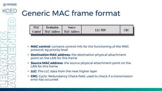
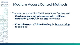
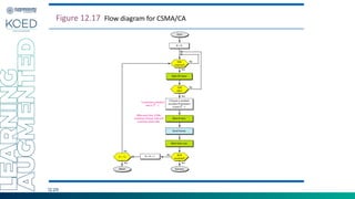
MAC
Ms. N. Jeba, AP/CSE
Department of Computer Science and
Engineering
Overview of this
Lecture
• MAC
• CSMA/CD
• CSMA/CA
Adapted from lecture slides by Behrouz A. Forouzan
12.3
Figure 12.1 Data link layer divided into two functionality-oriented sublayers
MEDIUM ACCESS CONTROL
• Assembly of data into frame with address and error
detection fields
• Disassembly of frame and performing of
• Address recognition
• Error detection
• Govern access to transmission medium
• Not found in traditional layer 2 data link control
• For the same LLC, several MAC options may be
available
Adapted from lecture slides by Behrouz A. Forouzan
MEDIUM ACCESS CONTROL
• All LANs and MANs consist of a collection of devices that must share the
network’s transmission capacity
• Some means of controlling access to the transmission medium is needed
for efficient use of that capacity. This is the function of a Medium Access
Control (MAC) Protocol.
• The key parameters in any MAC technique are where and how.
• Where, refers to whether control info is exercised in a centralized or distributed
fashion.
• Centralized: a controller has the authority to grant access to the network
• Distributed: the stations collectively perform a MAC function to determine
dynamically the order in which stations transmit
• How, is contrained by the topology and is a trade-off among competing
factors, such as cost, performance and complexity
Adapted from lecture slides by Behrouz A. Forouzan
6
Generic MAC frame format
• MAC control: contains control info for the functioning of the MAC
protocol, eg priority level
• Destination MAC address: the destination physical attachment
point on the LAN for this frame
• Source MAC address: the source physical attachment point on the
LAN for this frame
• LLC: The LLC data from the next higher layer
• CRC: Cyclic Redundancy Check field, used to check if a transmission
error has occurred
7
MAC techniques
• Synchronous
• A specific capacity is dedicated to a connection
• Same approach as in circuit-switching FDM or TDM, so not
optimal for LANs/MANs because the needs of the stations
are unpredictable
• Asynchronous
• Capacity is allocated in a dynamic fashion, in response to
demand
• Subdivided into three categories
• Round Robin
• Reservation
• Contention
8
Asynchronous MAC
techniques
• Round Robin
• Each station in turn is granted the right to transmit
• After each station finishes transmitting, it passes the right to transmit to the
next station in logical sequence
• Efficient technique when many stations have data to transmit over an
extended period of time
• Reservation
• For stream traffic (voice, bulk file transfer etc)
• Time on the medium is divided into slots, like synchronous TDM
• A station whishing to transmit reserves slots for an extended period
• Contention
• For bursty traffic (short, sporadic transmissions such as interactive terminal-
host traffic)
• No control is exercised to determine whose turn it is
• Simple to implement and efficient for light loads
I-Persistent Method
• After the station finds the line idle, it sends its frame
immediately (with probability I).
• This method has the highest chance of collision because two
or more stations may find the line idle and send their frames
immediately.
Adapted from lecture slides by Behrouz A. Forouzan
Non Persistent
• a station that has a frame to send senses the line. If the line is
idle, it sends immediately. If the line is not idle, it waits a
random amount of time and then senses the line again.
• The nonpersistent approach reduces the chance of collision
because it is unlikely that two or more stations will wait the
same amount of time and retry to send simultaneously.
• However, this method reduces the efficiency of the network
because the medium remains idle when there may be stations
with frames to send.
Adapted from lecture slides by Behrouz A. Forouzan
Persistent
• The p-persistent method is used if the channel has time slots
with a slot duration equal to or greater than the maximum
propagation time.
• The p-persistent approach combines the advantages of the
other two strategies.
• It reduces the chance of collision and improves efficiency.
Adapted from lecture slides by Behrouz A. Forouzan
Persistent
• In this method, after the station finds the line idle it
follows these steps:
1. With probability p, the station sends its frame.
2. With probability q = 1 - p, the station waits for the
beginning of the next time slot and checks the line
again.
a. If the line is idle, it goes to step 1.
b. If the line is busy, it acts as though a collision has
occurred and uses the backoff procedure.
Adapted from lecture slides by Behrouz A. Forouzan
12.13
Figure 12.11 Flow diagram for three persistence methods
12.14
Figure 12.2 Taxonomy of multiple-access protocols discussed in this chapter
12.15
12-1 RANDOM ACCESS
In random access or contention methods, no station is superior to another station and
none is assigned the control over another. No station permits, or does not permit,
another station to send. At each instance, a station that has data to send uses a
procedure defined by the protocol to make a decision on whether or not to send.
ALOHA
Carrier Sense Multiple Access
Carrier Sense Multiple Access with Collision Detection
Carrier Sense Multiple Access with Collision Avoidance
Topics discussed in this section:
16
Medium Access Control Methods
• The methods used for Medium Access Control are:
• Carrier-sense multiple-access with collision
detection (CSMA/CD) for bus topologies
• Control token or Token Passing for bus and ring
topologies
17
CSMA/CD
• CSMA/CD is used only in bus type networks, where a
number of nodes share a common communication
channel (wire) known as the bus.
• CSMA/CD is used in traditional Ethernet
• Ethernet will be covered in detail in future lectures
18
CSMA/CD
A B D
C
A B D
C
A B D
C
A B D
C
JAM JAM JAM JAM JAM JAM
Carrier sense multiple access collision detect (CSMA/CD)
Carrier
Sense
Multiple
Access
Collision
Collision
Detection
(Backoff
Algorithm)
Collision
19
CSMA/CD operation
• The basic operation of CSMA/CD is as follows:
1. To transmit data, the source station assembles a packet comprising of
the destination address, the data and control info
2.The source station listens to the cable to determine if the bus is
currently in use. If so, it waits until the bus is free, else it transmits the
packet. This operation is known as carrier sensing.
3.During transmission, the source station continues to listen to the cable
to detect if another station has also initiated a transmission thus
causing a collision. This process is known as collision detection.
4.If a collision is detected then, to ensure all stations are aware of the
collision, the source station transmits a random bit pattern known as
the jam sequence.
5.Stations involved in a collision then back off for a random period
before retrying for packet transmission.
20
CSMA/CD procedure
• Sense the channel
• If idle, transmit immediately
• If busy, wait until the channel becomes idle
• Collision detection
• Abort a transmission immediately if a collision is detected
• Try again later after waiting a random amount of time
21
Collision detection time
How long does it take to realize there has been a collision?
Worst case: 2 x end-to-end propagation delay
Station
A
Station
B
packet
tprop
12.22
Figure 12.12 Collision of the first bit in CSMA/CD
12.23
A network using CSMA/CD has a bandwidth of 10 Mbps. If the maximum propagation time
(including the delays in the devices and ignoring the time needed to send a jamming signal,
as we see later) is 25.6 μs, what is the minimum size of the frame?
Example 12.5
Solution
The frame transmission time is Tfr = 2 × Tp = 51.2 μs. This means, in the worst case, a station
needs to transmit for a period of 51.2 μs to detect the collision. The minimum size of the
frame is 10 Mbps × 51.2 μs = 512 bits or 64 bytes. This is actually the minimum size of the
frame for Standard Ethernet.
12.24
Figure 12.14 Flow diagram for the CSMA/CD
12.25
Figure 12.15 Energy level during transmission, idleness, or collision
12.26
Figure 12.16 Timing in CSMA/CA
12.27
In CSMA/CA, the IFS can also be used to
define the priority of a station or a frame.
Note
12.28
In CSMA/CA, if the station finds the
channel busy, it does not restart the timer of
the contention window;
it stops the timer and restarts it when the
channel becomes idle.
Note
12.29
Figure 12.17 Flow diagram for CSMA/CA
Summary
• MAC
• CSMA/CD
• CSMA/CA
Adapted from lecture slides by Behrouz A. Forouzan
References
• Behrouz A Forouzan, “Data Communications and
Networking”, Fifth edition, Tata McGraw–Hill, New
Delhi, 2013.
• Larry L. Peterson, Bruce S. Davie, “Computer
Networks: A Systems Approach”, Fifth edition,
Morgan Kaufmann Publishers Inc., 2011.
Adapted from lecture slides by Behrouz A. Forouzan
Medium access control. MAC Protocol.Data link layer

Medium access control. MAC Protocol.Data link layer

  • 1.
    MAC Ms. N. Jeba,AP/CSE Department of Computer Science and Engineering
  • 2.
    Overview of this Lecture •MAC • CSMA/CD • CSMA/CA Adapted from lecture slides by Behrouz A. Forouzan
  • 3.
    12.3 Figure 12.1 Datalink layer divided into two functionality-oriented sublayers
  • 4.
    MEDIUM ACCESS CONTROL •Assembly of data into frame with address and error detection fields • Disassembly of frame and performing of • Address recognition • Error detection • Govern access to transmission medium • Not found in traditional layer 2 data link control • For the same LLC, several MAC options may be available Adapted from lecture slides by Behrouz A. Forouzan
  • 5.
    MEDIUM ACCESS CONTROL •All LANs and MANs consist of a collection of devices that must share the network’s transmission capacity • Some means of controlling access to the transmission medium is needed for efficient use of that capacity. This is the function of a Medium Access Control (MAC) Protocol. • The key parameters in any MAC technique are where and how. • Where, refers to whether control info is exercised in a centralized or distributed fashion. • Centralized: a controller has the authority to grant access to the network • Distributed: the stations collectively perform a MAC function to determine dynamically the order in which stations transmit • How, is contrained by the topology and is a trade-off among competing factors, such as cost, performance and complexity Adapted from lecture slides by Behrouz A. Forouzan
  • 6.
    6 Generic MAC frameformat • MAC control: contains control info for the functioning of the MAC protocol, eg priority level • Destination MAC address: the destination physical attachment point on the LAN for this frame • Source MAC address: the source physical attachment point on the LAN for this frame • LLC: The LLC data from the next higher layer • CRC: Cyclic Redundancy Check field, used to check if a transmission error has occurred
  • 7.
    7 MAC techniques • Synchronous •A specific capacity is dedicated to a connection • Same approach as in circuit-switching FDM or TDM, so not optimal for LANs/MANs because the needs of the stations are unpredictable • Asynchronous • Capacity is allocated in a dynamic fashion, in response to demand • Subdivided into three categories • Round Robin • Reservation • Contention
  • 8.
    8 Asynchronous MAC techniques • RoundRobin • Each station in turn is granted the right to transmit • After each station finishes transmitting, it passes the right to transmit to the next station in logical sequence • Efficient technique when many stations have data to transmit over an extended period of time • Reservation • For stream traffic (voice, bulk file transfer etc) • Time on the medium is divided into slots, like synchronous TDM • A station whishing to transmit reserves slots for an extended period • Contention • For bursty traffic (short, sporadic transmissions such as interactive terminal- host traffic) • No control is exercised to determine whose turn it is • Simple to implement and efficient for light loads
  • 9.
    I-Persistent Method • Afterthe station finds the line idle, it sends its frame immediately (with probability I). • This method has the highest chance of collision because two or more stations may find the line idle and send their frames immediately. Adapted from lecture slides by Behrouz A. Forouzan
  • 10.
    Non Persistent • astation that has a frame to send senses the line. If the line is idle, it sends immediately. If the line is not idle, it waits a random amount of time and then senses the line again. • The nonpersistent approach reduces the chance of collision because it is unlikely that two or more stations will wait the same amount of time and retry to send simultaneously. • However, this method reduces the efficiency of the network because the medium remains idle when there may be stations with frames to send. Adapted from lecture slides by Behrouz A. Forouzan
  • 11.
    Persistent • The p-persistentmethod is used if the channel has time slots with a slot duration equal to or greater than the maximum propagation time. • The p-persistent approach combines the advantages of the other two strategies. • It reduces the chance of collision and improves efficiency. Adapted from lecture slides by Behrouz A. Forouzan
  • 12.
    Persistent • In thismethod, after the station finds the line idle it follows these steps: 1. With probability p, the station sends its frame. 2. With probability q = 1 - p, the station waits for the beginning of the next time slot and checks the line again. a. If the line is idle, it goes to step 1. b. If the line is busy, it acts as though a collision has occurred and uses the backoff procedure. Adapted from lecture slides by Behrouz A. Forouzan
  • 13.
    12.13 Figure 12.11 Flowdiagram for three persistence methods
  • 14.
    12.14 Figure 12.2 Taxonomyof multiple-access protocols discussed in this chapter
  • 15.
    12.15 12-1 RANDOM ACCESS Inrandom access or contention methods, no station is superior to another station and none is assigned the control over another. No station permits, or does not permit, another station to send. At each instance, a station that has data to send uses a procedure defined by the protocol to make a decision on whether or not to send. ALOHA Carrier Sense Multiple Access Carrier Sense Multiple Access with Collision Detection Carrier Sense Multiple Access with Collision Avoidance Topics discussed in this section:
  • 16.
    16 Medium Access ControlMethods • The methods used for Medium Access Control are: • Carrier-sense multiple-access with collision detection (CSMA/CD) for bus topologies • Control token or Token Passing for bus and ring topologies
  • 17.
    17 CSMA/CD • CSMA/CD isused only in bus type networks, where a number of nodes share a common communication channel (wire) known as the bus. • CSMA/CD is used in traditional Ethernet • Ethernet will be covered in detail in future lectures
  • 18.
    18 CSMA/CD A B D C AB D C A B D C A B D C JAM JAM JAM JAM JAM JAM Carrier sense multiple access collision detect (CSMA/CD) Carrier Sense Multiple Access Collision Collision Detection (Backoff Algorithm) Collision
  • 19.
    19 CSMA/CD operation • Thebasic operation of CSMA/CD is as follows: 1. To transmit data, the source station assembles a packet comprising of the destination address, the data and control info 2.The source station listens to the cable to determine if the bus is currently in use. If so, it waits until the bus is free, else it transmits the packet. This operation is known as carrier sensing. 3.During transmission, the source station continues to listen to the cable to detect if another station has also initiated a transmission thus causing a collision. This process is known as collision detection. 4.If a collision is detected then, to ensure all stations are aware of the collision, the source station transmits a random bit pattern known as the jam sequence. 5.Stations involved in a collision then back off for a random period before retrying for packet transmission.
  • 20.
    20 CSMA/CD procedure • Sensethe channel • If idle, transmit immediately • If busy, wait until the channel becomes idle • Collision detection • Abort a transmission immediately if a collision is detected • Try again later after waiting a random amount of time
  • 21.
    21 Collision detection time Howlong does it take to realize there has been a collision? Worst case: 2 x end-to-end propagation delay Station A Station B packet tprop
  • 22.
    12.22 Figure 12.12 Collisionof the first bit in CSMA/CD
  • 23.
    12.23 A network usingCSMA/CD has a bandwidth of 10 Mbps. If the maximum propagation time (including the delays in the devices and ignoring the time needed to send a jamming signal, as we see later) is 25.6 μs, what is the minimum size of the frame? Example 12.5 Solution The frame transmission time is Tfr = 2 × Tp = 51.2 μs. This means, in the worst case, a station needs to transmit for a period of 51.2 μs to detect the collision. The minimum size of the frame is 10 Mbps × 51.2 μs = 512 bits or 64 bytes. This is actually the minimum size of the frame for Standard Ethernet.
  • 24.
    12.24 Figure 12.14 Flowdiagram for the CSMA/CD
  • 25.
    12.25 Figure 12.15 Energylevel during transmission, idleness, or collision
  • 26.
  • 27.
    12.27 In CSMA/CA, theIFS can also be used to define the priority of a station or a frame. Note
  • 28.
    12.28 In CSMA/CA, ifthe station finds the channel busy, it does not restart the timer of the contention window; it stops the timer and restarts it when the channel becomes idle. Note
  • 29.
    12.29 Figure 12.17 Flowdiagram for CSMA/CA
  • 30.
    Summary • MAC • CSMA/CD •CSMA/CA Adapted from lecture slides by Behrouz A. Forouzan
  • 31.
    References • Behrouz AForouzan, “Data Communications and Networking”, Fifth edition, Tata McGraw–Hill, New Delhi, 2013. • Larry L. Peterson, Bruce S. Davie, “Computer Networks: A Systems Approach”, Fifth edition, Morgan Kaufmann Publishers Inc., 2011. Adapted from lecture slides by Behrouz A. Forouzan