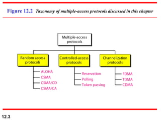
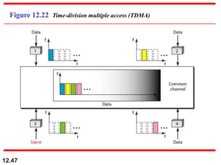
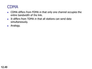
This document discusses multiple access protocols for sharing a communication channel between multiple stations. It covers both random access protocols like ALOHA and slotted ALOHA, and controlled access protocols like polling, token passing, and reservation. It also discusses channelization protocols for sharing bandwidth, including Frequency-Division Multiple Access (FDMA), Time-Division Multiple Access (TDMA), and Code-Division Multiple Access (CDMA). FDMA divides the channel into frequency bands, TDMA divides it into time slots, and CDMA allows all stations to transmit simultaneously using unique coding. The document provides detailed explanations, examples, diagrams and equations for each protocol.
![12.61
Find the chips for a network with
a. Two stations b. Four stations
Example 12.6
Solution
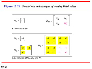
We can use the rows of W2 and W4 in Figure 12.29:
a. For a two-station network, we have
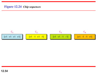
[+1 +1] and [+1 −1].
b. For a four-station network we have
[+1 +1 +1 +1], [+1 −1 +1 −1],
[+1 +1 −1 −1], and [+1 −1 −1 +1].](https://image.slidesharecdn.com/multipleaccess-240118144049-b266570e/85/Multiple-Access-ppt-in-Object-Oriented-Programming-61-320.jpg)