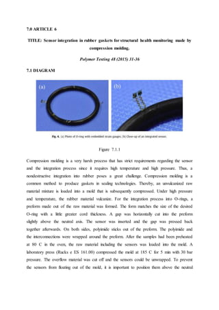
- Compression molding is used to integrate sensors into rubber gaskets for structural health monitoring.
- In compression molding, an unvulcanized raw material mixture is loaded into a mold and compressed under high pressure and temperature to vulcanize the rubber.
- For sensor integration, a preform was made matching the size of an O-ring with a cut gap for sensor insertion. The gap was pressed back together after inserting the sensor.
this ppt pdf beneficial for 1st year engineering student who studying workshop technology. in this pdf types of joining, gas welding, arc welding, spot welding, tig welding, mig welding, soldering brazing and different welding defect has been discussed.
Ekeeda Provides Online Engineering Subjects Video Lectures and Tutorials of Mumbai University (MU) Courses. Visit us: https://ekeeda.com/streamdetails/University/Mumbai-University
Fabrication of Plastics in polymer technology for B.Tech students in India specially for JNTU K,H&A in Andhra Pradesh Telangana and also for other Indian Universities.
By
Gurram.Achyuth Kumar
A
This is also called as moulding of plastics into articles. To give shapes to plastics, several methods of fabrication are used. They are
1. Compression moulding
2. Injection moulding
3. Transfer moulding
4. Extrusion moulding
Infomatica, as it stands today, is a manifestation of our values, toil, and dedication towards imparting knowledge to the pupils of the society. Visit us: http://www.infomaticaacademy.com/
Powder Metallurgy enables the processing of materials with very high melting points, including refractory metals such as tungsten, molybdenum, and tantalum. Such metals are very difficult to produce by melting and casting and are often very brittle in the cast state.
Advantages of Powder Metallurgy
It can be very economical for mass production (100,000 parts). Long term reliability through close control of dimensions and physical properties. Very good material utilization - loss of material very less. Minimization or elimination of Machining.
Explore the innovative world of trenchless pipe repair with our comprehensive guide, "The Benefits and Techniques of Trenchless Pipe Repair." This document delves into the modern methods of repairing underground pipes without the need for extensive excavation, highlighting the numerous advantages and the latest techniques used in the industry.
Learn about the cost savings, reduced environmental impact, and minimal disruption associated with trenchless technology. Discover detailed explanations of popular techniques such as pipe bursting, cured-in-place pipe (CIPP) lining, and directional drilling. Understand how these methods can be applied to various types of infrastructure, from residential plumbing to large-scale municipal systems.
Ideal for homeowners, contractors, engineers, and anyone interested in modern plumbing solutions, this guide provides valuable insights into why trenchless pipe repair is becoming the preferred choice for pipe rehabilitation. Stay informed about the latest advancements and best practices in the field.
Industrial Training at Shahjalal Fertilizer Company Limited (SFCL)MdTanvirMahtab2
This presentation is about the working procedure of Shahjalal Fertilizer Company Limited (SFCL). A Govt. owned Company of Bangladesh Chemical Industries Corporation under Ministry of Industries.
Water scarcity is the lack of fresh water resources to meet the standard water demand. There are two type of water scarcity. One is physical. The other is economic water scarcity.
Student information management system project report ii.pdfKamal Acharya
Our project explains about the student management. This project mainly explains the various actions related to student details. This project shows some ease in adding, editing and deleting the student details. It also provides a less time consuming process for viewing, adding, editing and deleting the marks of the students.
CFD Simulation of By-pass Flow in a HRSG module by R&R Consult.pptxR&R Consult
CFD analysis is incredibly effective at solving mysteries and improving the performance of complex systems!
Here's a great example: At a large natural gas-fired power plant, where they use waste heat to generate steam and energy, they were puzzled that their boiler wasn't producing as much steam as expected.
R&R and Tetra Engineering Group Inc. were asked to solve the issue with reduced steam production.
An inspection had shown that a significant amount of hot flue gas was bypassing the boiler tubes, where the heat was supposed to be transferred.
R&R Consult conducted a CFD analysis, which revealed that 6.3% of the flue gas was bypassing the boiler tubes without transferring heat. The analysis also showed that the flue gas was instead being directed along the sides of the boiler and between the modules that were supposed to capture the heat. This was the cause of the reduced performance.
Based on our results, Tetra Engineering installed covering plates to reduce the bypass flow. This improved the boiler's performance and increased electricity production.
It is always satisfying when we can help solve complex challenges like this. Do your systems also need a check-up or optimization? Give us a call!
Work done in cooperation with James Malloy and David Moelling from Tetra Engineering.
More examples of our work https://www.r-r-consult.dk/en/cases-en/
Overview of the fundamental roles in Hydropower generation and the components involved in wider Electrical Engineering.
This paper presents the design and construction of hydroelectric dams from the hydrologist’s survey of the valley before construction, all aspects and involved disciplines, fluid dynamics, structural engineering, generation and mains frequency regulation to the very transmission of power through the network in the United Kingdom.
Author: Robbie Edward Sayers
Collaborators and co editors: Charlie Sims and Connor Healey.
(C) 2024 Robbie E. Sayers
Cosmetic shop management system project report.pdfKamal Acharya
Buying new cosmetic products is difficult. It can even be scary for those who have sensitive skin and are prone to skin trouble. The information needed to alleviate this problem is on the back of each product, but it's thought to interpret those ingredient lists unless you have a background in chemistry.
Instead of buying and hoping for the best, we can use data science to help us predict which products may be good fits for us. It includes various function programs to do the above mentioned tasks.
Data file handling has been effectively used in the program.
The automated cosmetic shop management system should deal with the automation of general workflow and administration process of the shop. The main processes of the system focus on customer's request where the system is able to search the most appropriate products and deliver it to the customers. It should help the employees to quickly identify the list of cosmetic product that have reached the minimum quantity and also keep a track of expired date for each cosmetic product. It should help the employees to find the rack number in which the product is placed.It is also Faster and more efficient way.
3. 1.0 Introduction of Compression Molding
Compression molding is the process of molding a material in a confined shape by
applying pressure and usually heat or can use hydraulic ram. The material used usually for
thermosetting plastic. The process including two step which is first is Pre-heating and
secondly is pressurizing. Example of the product used this type of molding such as
manufacturing of high scale of buckles, large container, electronic devices cases and etc.
Some of advantage by using this process is cost efficient where this process required
less tool, suitable for high scale production including mass and batch production because of
this process can be in continuous lesser step and capable producing large components
because of the capability using a one big shot compounds.
Some disadvantage by using this process is curing time is large where it takes longer
time to cool down the resin so it can removed. There also creating uneven parting lines at the
surface of the product and required cleaning or finishing process. The most significant
disadvantages from is using a material of thermoset which cannot reproduced scrap back to
the polymer states and it cost lot of time to reproduce the same charges.
Figure 1.1 The components of Compression Molding
From this figure (fig.1.1), shows the components of compression molding. The upper
mold can called Female mold and this mold can be move up and down. The Lower mold can
called Male mold and cannot be moved or fixed. The charge is a molding compound usually
in granules form and placed into the bottom half a heated mold. The ejector pin is used to
remove the finished product.
4. Figure 1.2 The Process description of Compression Molding
This figure (fig. 1.2) shows the step by step process throughout the process of
compression molding. First step is molding compound or charges in forms of granules or
powder placed into the bottom half lower heated mold. Secondly, the mold ready to closed by
bringing the upper mold to lower mold together. Then, the pressure is exerted to squeeze the
resin so it can fills up the mold cavity. while under pressure by heat the mold is heated to
polymerize and cure the material into solidified part. Lastly, after curing time, the mold
valves was open and ready to remove the product from cavity by using the enjectors pin.
5. 2.0 ARTICLE 1
TITLE:
Carbohydrate Polymers: Active bilayer films of thermoplastic starch and
polycaprolactone obtained by compression molding.
Carbohydrate Polymers Volume 127, 20 August 2015, Pages 282-290.
2.1 DIAGRAM
Figure 2.1.1 DGTA curves of bilayer films showing peaks for starch degradation and PCL
degradation.
6. This graph (fig. 2.1 ) shows the thermogravimetric analysis or DGTA curves of
bilayers with S layer (A) and bilayers with S95 layer (B) by displaying the peaks of thermal
degradation that correlated with the different weight losses. With the help of this graph we
can studies the thermal stability effects of polymers by adding the compounds at the
interface. At the 50 celcius and 100 celcius represent the evaporation of bonded water.
Meanwhile, at the 283 celcius and 290 celcius represent the starch thermal degradation. At
374 celcius represent the part of PCL thermal degradation.
2.2 SUMMARY
DGTA shows the curves of each bilayers by showing the peaks correlated with the
different weight loss caused by thermal degradation. (Fig. 2.1)
GTA provided shows about the effect of compounds added at the interface on the
thermal stability of polymers due to the diffusion into the layers and potential
interactions with each macromolecule.
For Bilayers with S layer (A) showed the highest thermal stability, although it
promoted the thermal degradation of starch and PCL
For bilayers with S95 (B) layer provoked a significant increase by p > 0.05 in the
starch degradation temperature (onset and peak) while the onset temperature of PCL
phase also rose
This indicates that polymer interactions improved the thermal stability of both phases.
In bilayers, degradation temperatures of both starch and PCL increased (more in the
case of starch), except when PS was added. In these cases, the thermal degradation of
polymers in bilayers occurred at a lower temperature than in the corresponding
monolayer.
2.3 REFERENCE
Ortego, Morey, P. T & A. C. (20 August, 2015). Active bilayer films of thermoplastic starch
and polycaprolactone obtained by compression molding article. Active bilayer films of
thermoplastic starch and polycaprolactone obtained by compression molding article.
Retrieved March 19, 2018
7. 3.0 ARTICLE 2
TITLE:
Method of molding composite plastic sheet material to form a compression molded,
deep-drawn article, 14 July 2016.
3.1 DIAGRAM
Figure 3.1.1
The manufacturing of parts (fig. 3.1.1) with quite difficult shapes uses compression
molding compared to transfer molding or injection molding when it comes to thermoplastics
due to low cost and ability to limit the waste of material. In this method of deep drawing, the
material about to be molded is positioned in the mold cavity, between the male and female
die with the female die having an article-defining cavity that shapes the material into a
desired final product. A hydraulic ram closed the heated platens. Pressure and heat is applied
on the material and the material takes the shape of the article-defining cavity until curing
reaction takes place. The mold is then cooled and the part is removed from the mold. Since
deep drawing process consist of molding the material into a shape with a depth that exceeds
the drawn diameter, the process have to be repeated through a series of dies before the
desired dimension is achieved. Due to this, the flange region of the material is subject to
8. compressive stresses that cause wrinkling during the process. The wrinkles can be controlled
using a blank holder, and does not significantly stretch or tear the material from the pressure
of the male die due to the clamping technique of the mechanism.
3.2 SUMMARY
● A method of molding composite thermoplastic sheet that includes a heated material
placed on a die with article defining cavity in the inner surface.
● The inner or middle portion of the sheet is forced into the die to acquire the desired
shape of the article-defining cavity.
● The outer portion of the sheet is held to resist movement of the peripheral portion into
the die during the punching process.
● The holding mechanism consist of many outer parts of the sheets to be held, almost
covering the entire perimeter in order to control the wrinkling, tearing or ripping of
the material during the deep-drawing process.
● This holding step also increases at the material is punched into the die.
3.3 REFERENCE
Preisler, D. J., & Heikkila, C. A. (14 June, 2016). Method of molding composite plastic sheet
material to form a compression molded, deep-drawn article. Method of Molding Composite
Plastic Sheet Material to Form a Compression Molded, Deep-drawn Article. Retrieved
March 19, 2018.
9. 4.0 ARTICLE 3
TITLE:
Comparative Characterization Of Bovine And Fish Gelatin Film Fabricated By
Compression Molding And Solution Casting Method
Volume 26, March 2018, Pages 1239-1252
4.1 DIAGRAM
PREPARATION OF FILM BY THERMO-COMPRESSION MOLDING
Figure 4.1.1 Schematic Illustration of compression molding method.
Thermo-molding compression method were used to produce a films as shown in
Figure 1. The conditioned resins about 3 g were placed between two stainless steel plates
(10 × 10 inch2) covered with Mylar sheets. The set was inserted between heating platens of
the compression molder prior heated to 120 °C and the resin was then preheated at this
temperature for 10 min without pressure. The molten resin was subsequently pressed to form
a film in the compression molder at 120 °C. A pressure of 20 MPa was applied for 2 min,
followed by removal of the set from the compression molder and allowing to cool down to
room temperature within 3 min. The gelatin film could be easily removed from the plates and
was subjected to analyses.
10. 4.2 SUMMARY
● Gelatin films produced from solution casting method had better overall properties
such as mechanical, water–vapor barrier, optical and thermal properties, compared to
those made from thermo-compression molding method.
● Thermal degradation of gelatins upon compression-molded film preparation at high
temperature played a crucial role on lower properties of the resulting films
● Films that was fabricated by thermal technique at optimal processing conditions
would be cost-effective and most suitable technique for large-scale production.
● Thermo-compression molding require less processing time and space, which make
this technique still appropriate for further development of commercial biodegradable
protein-based films.
4.3 REFERENCES
Chuaynukul, Kajornsak, et al. “Comparative Characterization of Bovine and Fish Gelatin
Films Fabricated by Compression Molding and Solution Casting Methods.” Journal of
Polymers and the Environment, vol. 26, no. 3, 2017, pp. 1239–1252., doi:10.1007/s10924-
017-1030-5.
11. 5.0 ARTICLE 4
TITLE:
Investigation on Mechanical Behaviour of Twisted Natural Fiber Hybrid Composite
Fabricated by Vacuum Assisted Compression Molding Technique.
Fibre and Polymers 2016. Vol 7. No.1, 80-87
5.1 DIAGRAM
Figure 5.1.1
The main objective of this paper was to introduce a new concept of fibre twisting and
to investigate the effect of twisting and the fibre orientation on the mechanical properties of
bio degradable green composites. The composite is fabricated by vacuum assisted
compression molding technique in which the problems of hand lay process are eliminated.
Although there are many method available, Compression moulding assist by vacuum was
choose because it is highly reliable and more efficient than other method. In this process, the
draw backs of other method are overcome by using vacuum inside the mold to avoid air trap
formed inside the composite. The material was arranged differently into 3 type.
Type I Type II Type III
Glass fibre Glass fibre Glass fibre
Twisted neem fibre
(horizontal)
Twisted neem fibre
(horizontal)
Twisted neem fibre
(vertical)
Twisted kenaf fibre Twisted kenaf fibre Twisted kenaf fibre
12. (horizontal) (vertical) (inclined )
Twisted neem fibre
(horizontal)
Twisted neem fibre
(horizontal)
Twisted neem fibre
(vertical)
Glass fiber Glass fiber Glass fiber
Figure above show a process manufacturing fibre composites using compression
moulding assisted by vacuum. There are 3 stage for this process. First, based on figure (a),
vacuum shield is created inside the mold box. After that, all the fibre will placed in three
different orientations as shown in figure (b). Lastly, the figure (c) show the wood pattern with
the foam is used for compressing the fibre layer. After forming the required combination, the
mold is allowed to dry for 5 hours and then the fabricated composite laminate is ejected from
the mold for further processing.
5.2 SUMMARY
By using the composite fabricated by the vacuum, the composite was test by various
test such as tensile, flexural, double shear, impact and inter delamination test for
twisted fiber composite.
The twisted kenaf and neem fibre was arranged in 3 type of orientations using vacuum
assisted compression moulding.
From the experiment, properties type III in tensile, flexural, impact and double shear
properties is higher than types II and type I.
While in inter delamination test, type II exhibit better properties followed by type III
and type I.
It can be conclude that the composite twisted fiber and 45 degree fiber orientations
have better mechanical properties than the others.
5.3 REFERENCE
Ramnath, B. V., Rajesh, S., Elanchezhian, C., Shankar, A. S., Pandian, S. P., Vickneshwaran,
S., & Rajan, R. S. (2016). Investigation on mechanical behaviour of twisted natural
fiber hybrid composite fabricated by vacuum assisted compression molding
technique. Fibers and Polymers, 17(1), 80-87. Retrieved March 9, 2018
13. 6.0 ARTICLE 5
Title:
Development of a Combined Process of Organic Sheet forming and GMT Compression
Molding
Bernd-Arno Behrens, Sven Hübner, Christian Bonk, Florian Bohne, Moritz Micke-Camuz *
Procedia Engineering 207 (2017) 101–106
This research explained the latest development of one-step process which combined complex
organic sheet forming and GMT (Glass Mat Thermoplastics) compression molding by using
conventional stamping technology. Therefore, injection molding process does not required.
Compression molding allows adding a third dimension to the two-dimensional organic sheet.
The application of fiber-reinforced plastics (FRP) is in automotive lightweight design such as
interior or under body parts and front ends components. Moreover, it is necessary to develop
large-scale processes of FRP as there is increasing use of multi-material constructions in
lightweight application. FRP also has high demand in the automobile industry.
Process steps:
6.1 Diagram
Figure 6.1.1
Figure 6.1.2
14. The organic sheet and GMT material were heated in an external infra-red (IR) radiator to
260°C. The cycle time can be reduced by decoupling the heating from forming process.
However, there is higher chance of cooling process while transferring the material.
1. The GMT material is placed into the tunnel pocket of the lower die which is heated at
110°C.
2. The clamping frame is positioned above the stamp without tool contact.
3. Then, the tool closes with a velocity of 45 mm/s and the part is formed. Notes: The
clamping frame is used to restrain the material and induce fiber shear and yarn
straightening to prevent wrinkling of the organic sheet.
When the organic sheet comes into contact with the GMT material, the cavities are
already sealed at the end faces by the organic sheet. Furthermore, sealing occurs at the
5° steep flanks of the tunnel between the organic sheet and the lower tool.
4. At the end of the process, the two components have to be joined and both materials
have to be reconsolidated.
5. The part can be removed after a dwell time of 10s with a pressing force.
6.2 SUMMARY
• One process step – combination of two processes.
• Shorter life cycle, less than 20s.
• Can be applied for large-scale industry.
• Improving mechanical properties.
• Application: fiber-reinforced plastics in automotive lightweight design (eg: interior
components)
6.3 REFERENCE
Development of a Combined Process of Organic Sheet forming and GMT Compression
Molding. (2017, November 15). Retrieved March 19, 2018, from
https://www.sciencedirect.com/science/article/pii/S1877705817355200
15. 7.0 ARTICLE 6
TITLE: Sensor integration in rubber gaskets for structural health monitoring made by
compression molding.
Polymer Testing 48 (2015) 31-36
7.1 DIAGRAM
Figure 7.1.1
Compression molding is a very harsh process that has strict requirements regarding the sensor
and the integration process since it requires high temperature and high pressure. Thus, a
nondestructive integration into rubber poses a great challenge. Compression molding is a
common method to produce gaskets in sealing technologies. Thereby, an unvulcanized raw
material mixture is loaded into a mold that is subsequently compressed. Under high pressure
and temperature, the rubber material vulcanize. For the integration process into O-rings, a
preform made out of the raw material was formed. The form matches the size of the desired
O-ring with a little greater cord thickness. A gap was horizontally cut into the preform
slightly above the neutral axis. The sensor was inserted and the gap was pressed back
together afterwards. On both sides, polyimide sticks out of the preform. The polyimide and
the interconnections were wrapped around the preform. After the samples had been preheated
at 80 C in the oven, the raw material including the sensors was loaded into the mold. A
laboratory press (Rucks e ES 161.00) compressed the mold at 185 C for 5 min with 30 bar
pressure. The overflow material was cut off and the sensors could be unwrapped. To prevent
the sensors from floating out of the mold, it is important to position them above the neutral
16. axis. Otherwise, it was observed that the sensor either floats out together with the excessive
elastomer or is torn apart. An O-ring with embedded sensors is exhibited in Fig. 4.
During aging of the rubber material, the compression set increases over time. Simultaneously,
the restoring forces inside the elastomer diminish. The change of the compression set is
accelerated by applying high temperatures. This behavior is exploited in order to monitor and
evaluate the degradation behavior of rubber gaskets. In this work, the change in the strain
gauge signal in a compressed O-ring was analyzed over 72 h, while exposed to 70 C in an
oven.
7.2 SUMMARY
● The integration process of strain gauge sensors into rubber O-rings using compression
molding has been introduced.
● Strain gauges were non-destructively integrated into a vulcanized rubber. The sensor
functionality is proven.
● The contact force that is applied to the O-ring can be related to the change in
resistance of the embedded strain gauge. This allows a proper installation of the
gasket to be monitored.
● The change of the rubber properties during artificial aging of the O-ring can be
visualized by the sensor. The sensor signal greatly depends on the temperature. In
order to compensate the influence of the temperature, a second strain gauge can be
passively added. If this sensor is only exposed to the temperature and not the strain,
the temperature can be compensated by using a Wheatstone bridge to evaluate the
sensor signal that will be investigated in future development.
7.3 REFERENCE
W. Lang, F. Jakobs, E. Tolstosheeva, H. Sturm, A. Ibragimov, A. Kesel, D. Lehmhus, U.
DickeFrom embedded sensors to sensorial materials-The road to function scale integration
Sens. Actuat A-Phys, 171 (2011), pp. 3-11.