SlideShare a Scribd company logo
1 of 6
Surveying Principles Engineering
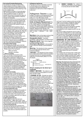
Surveying is the process of determining
relative positions of different objects on the
surface of the earth by measuring horizontal
distances betw een themand preparing a map
to any suitable scale.
Measurements are taken in horizontal plane
only. Surveying is the art of determining the
relative positions of points on, above or
beneath the surface of the earth by means of
direct or indirect measurements of distance,
direction and elevation.
Leveling is a branch of surveying the object of
w hich is to find the elevations of points w ith
respect to a given or assumed datum and to
establish points at a given elevation or at
different elevations with respectto a given or
assumed datum.
Survey is performed to prepare a map of
relative positions on surface of the earth. It
show sthe naturalfeature of a country such as
tow ns, villages, roads, railways, etc. They may
also include details of different engineering
w orks such as bridge, canal, dam etc.
Before commencement of any major
engineering project, survey is carried out to
determine the location of site and its
surrounding. To understand the topography of
the site and natural resource availability.
Survey is carried out to prepare the cadastral
map show ing propertyboundaries.
Principles of Surveying
The fundamental principle upon w hich the
various methods of plane surveying are based
can be stated under the follow ing two aspects.
. Primary types of Surveying are:
 Plane surveying
 Geodetic surveying
1. Plane surveying
Plane surveying is conducted by state
agencies as w ellas private agencies. As we
know earth is sphericalin shape but its
diameter is big enough to consider plane in
small dimensions. It is that type of surveying in
w hich the mean surface of the earth is
considered as a plane and the spheroidal
shape is neglected. All triangles formed by
survey lines are considered as plane triangles.
The level line is considered as straight and
plumb lines are considered parallel. Plane
surveying is done of the area of survey is less
than 250 km2
.
2. Geodetic surveying
Geodetic surveyis conducted by survey
department of the country. It is that type of
surveying in w hich the curved shape of the
earth is taken in to account. The object of
geodetic survey is to determine the precise
position on the surface of the earth, of a
systemof w idely distant points w hich form
controlstations in w hich surveysof less
precision may be referred. . Line joining tw o
points is considered as curved line and angles
are assumed as sphericalangles. It is carried
out if the area exceeds over 250 km2
a) Topographical Surveys
They are carried out determine the position of
natural features of a region such as rivers,
streams, hills etc. and artificialfeatures such
as roads and canals. The purpose of such
surveys is to prepare maps and such maps of
are called topo-sheets.
b) Hydrographic Survey
Hydro-graphic surveyis carried out to
determine M.S.L. (Mean Sea Level), w ater
spread area, depth of w ater bodies, velocityof
flow in streams, cross-section area of flow etc.
c) Astronomical Survey
The AstronomicalSurvey is carried out to
determine the absolute location of any point on
the surface of earth. The survey consistsof
making observations to heavenly bodies such
as stars.
d) Engineering Survey
This type of survey is undertaken w henever
sufficient data is to be collected for the
purpose of planning and designing
engineering w orks such as roads, bridges and
reservoirs.
Pythagorean Theorem In a right
triangle, the square of the hypotenuse is equal
to the sum of the squares of the other tw o
sides. C 2 = A2 + B2 w here: Cis the
hypotenuse (side opposite the right angle). A
and B are the remaining sides.
Units of Angular Measurement The
most common angular units being employed
in the United States is the Sexagesimal
System. This systemuses angular notation in
increments of 60 by dividing the circle into 360
degrees; degrees into 60 minutes; and
minutes into 60 seconds. Therefore; 1 circle =
360° = 21,600´ = 1,296,000˝ 1° = 60´ = 3600˝
1´ = 60
Meridian:A line on the mean surface of the
earth joining the north and south poles. •
Geographic North: True North
Sometimes called Geodedic True North-fixed •
Magnetic North: Taken froma magnetic
compasschanges with time
Grid North (Meridian): Lines parallel to
a grid reference meridian (centralmeridian)-
SPC
Bearing - The direction of a line as given by
the acute angle betw een the line and a
reference meridian.
Azimuth – The direction of a line as given
by an angle measurement clockw ise (usually)
fromthe north end of a reference meridian.
(NAD 83 is fromthe North) (NAD 27 is from
the South)
Direct ranging can be done by 2
methods:
DIRECT METHOD: This method is used
w hen two ends of surveystations or survey
lines are inter-visible.
1) RANGING BY EYE: Consider tw o pints X
and Y w hich are inter-visible to each other. In
this method ranging rod is fixed at station X
and Y. Suppose if w e w ant to locate a point Z
on ground w hich is in line w ith XY. The
surveyor standshalf a metre backside of
ranging rod at X in line w ith XY. Assistant then
moves another ranging rod under the
guidance of surveyor in such a w ay that
ranging rod hold by assistant is in the line XY
at point Z betw wen X ANDY. Similarly other
points can be located by similar w ay. Surveyor
has to guide assistant by using some hand
signals so that ranging rod comes in the line.
 INDIRECT RANGING: This method is
used w hen two ends of survey stations
or survey line are not inter-visible.
Let X and Y be the 2 stations w hich are not inter-
visible. So to proceed in straight line betw een X
and Y process of indirect ranging is applied.
Tw o intermediate points M1 and M2
are located in such a w ay that person standing
w ith ranging rod at M2 can see M1 and X
w hereasperson with ranging rod at M1 can see
M2 and Y.
Now person at M2 w illguide the person at M1 to
come in line w ith M2 and X on a new position M3.
Now the person at M3 w illguide the person at M2
to come to a new position M4 such that M3, M4
and Y are on same line. Ranging rod is fixed at
M3 & M4 and chaining is continued along the hill.
2)RANGING BY LINE RANGER:Line
ranger is a light and easy to use instrument w hich
can be used for ranging. It consists of 2 plane
mirrors or 2 right-angled isosceles prismplaces
one above the another. Diagonals of tw o prism
are silvered so as to reflect light. Low er prismis
fixed w hile the upper prism is moveable.
Instrument is provided w ith handle at bottom
w hich gives ease to the user for using the
instrument.
Tw o ranging rods are fixed at inter-visible points.
Then surveyor moves with the line ranger. The
point w here two images coincide in line ranger is
the point in line w ith two fixed ranging rods. At
this point a pebble is dropped from the handle of
line ranger and point is traced on ground.
2. Bearing • The bearing of a line is the horizontal
angle w hich it makes w ith a reference line
(meridian) depending upon the meridian, there
are four types of bearings. True Bearing The true
bearing of a line is the horizontal angle betw een
the true meridian and the survey line. The true
bearing is measured fromthe true north in the
clockw ise direction. Magnetic Bearing The
magnetic bearing of a line is the horizontalangle
w hich the line makes w ith the magnetic north.
3. 22. Bearing Grid Bearing The grid bearing of a
line is the horizontalangle w hich the line makes
w ith the grid meridian. Arbitrary Bearing The
arbitrary bearing of a line is the horizontal angle
w hich the line makes w ith the arbitrary meridian
4. 25. Designation of Bearings • The bearing are
designated in the follow ing two systems. • Whole
Circle Bearing System (W.C.B) • Quadrantal
Bearing System( Q.B.)
5. 26. Whole Circle Bearing System (W.C.B) • The
bearing of a line measured w ith respect to
magnetic meridian in clockw ise direction is called
magnetic bearing and its value varies betw een0
0 to 360 0. • The Quadrants start fromNorth and
Progress in a clockw ise direction as the first
quadrant is 0 0 to 90 0 in clockw ise direction, 2nd
90 0 to 180 0 , 3 rd 180 0 to 270 0 , and up to
360 0 is 4th one.
6. 28. Whole Circle Bearing System (W.C.B)
7. 29. Quadrant Bearing System (Q.B.) • In this
system, the bearing of survey lines are measured
w ith respect to north line or south line w hich ever
is the nearest to the given survey line and either
in clockw ise direction or in anticlockw ise
direction. • The bearing of lines w hich fallin Ist
and IV th Quadrant are measured w ith respect to
north line is nearer than south line, and bearing
of lines fallin II nd and IIIrd quadrants are
measured from south line as south is the nearer
line. The surveyor’s compassmeasures the
bearing of lines in the quadrant system.
1. 30. Reduced Bearing (RB) •
When the whole circle bearing of a line is
converted into quadrantal bearing itis
termed as ‘Reduced Bearing’.Thus,the
reduced bearing is similar to the
quadrantal bearing.It’s value lies
between 0 0 to 90 0, but the quadrants
should be mentioned for proper
designation.
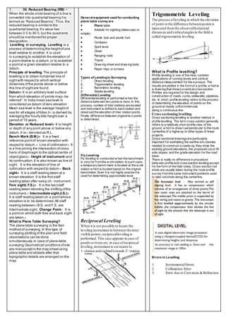
Levelling in surveying. Levelling is a
process ofdetermining the heightofone
level relative to another. It is used
in surveying to establish the elevation of
a pointrelative to a datum,or to establish
a pointat a given elevation relative to a
datum.
Principle of levelling The principle of
levelling is to obtain horizontal line of
sightwith respectto which vertical
distances ofthe points above or below
this line of sightare found.
Datum It is an arbitrary level surface
from which elevation of points may be
referred”. In India mean sea level is
considered as datum ofzero elevation
Mean sea level is the average heightof
sea for all stages oftides it is derived by
averaging the hourly tide heightover a
period of 19 years.
Elevation or Reduced level It is height
or depth of any point above or below any
datum.It is denoted as R.L.
Bench Mark (B.M.) It is a fixed
reference pointof known elevation with
respectto datum. Line of collimation It
is a line joining the intersection ofcross
hairs of diaphragm to the optical centre of
objectglass Height of instrumentand
its continuation.It is also known as line of
sight. It is the elevation of line of
collimation with respectto datum Back
sight It is a staff reading taken at a
known elevation. It is the firststaff
reading taken after setup of instrument.
Fore sight( F.S.) It is the laststaff
reading taken denoting the shifting ofthe
instrument. Intermediate sight.(I.S.)
It is staff reading taken on a pointwhose
elevation is to be determined.All staff
reading betweenB.S. and F.S. are
Intermediate sight. Change Point It is
a pointon which both fore and back sight
are taken.
What is Plane Table Surveying?
The plane table surveying is the fast
method of surveying. In this type of
surveying plotting of the plan and field
observations can be done
simultaneously.In case of plane table
surveying Geometrical conditions ofsite
are manuscriptin the map sheetusing
plane table and alidade after that
topographic details are arranged on the
map.
General equipment used for conducting
plane table survey are
 Plane table
 Alidade for sighting (telescopic or
simple)
 Plumb bob and plumb fork
 Compass
 Spirit level
 Chain
 Ranging rods
 Tripod
 Draw ing sheet and draw ing tools
 Paper clips or screws
Types of Levelingin Surveying
1. Direct leveling
2. Trigonometric leveling
3. Barometric leveling
4. Stadia leveling
Differential Leveling
Differentialleveling is performed w hen the
distance betw een two points is more. In this
process, number of inter stations are located
and instrument is shifted to each station and
observed the elevation of inter station points.
Finally difference between originaltw o points
is determined.
Fly Leveling
Fly leveling is conducted w hen the benchmark
is very far fromthe w orkstation. In such case,
a temporary bench mark is located at the w ork
station w hich is located based on the original
benchmark. Even it is not highly precise it is
used for determining approximate level.
Reciprocal Leveling
When it is not possible to locate the
leveling instrument in between theinter
visible points,reciprocalleveling is
performed.This case appears in case of
pondsorrivers etc.in case ofreciprocal
leveling,instrument is set nearerto
1st
station andsightedtowards 2nd
station.
Trigonometric Leveling
The process ofleveling in which the elevation
of point orthe difference betweenpointsis
measured fromthe observedhorizontal
distances andverticalanglesin the field is
called trigonometric leveling.
What is Profile levelling?
Profile leveling is one of the most common
applications of running levels and vertical
distance measurement for the surveyor. The
results are plotted in the formof a profile, w hich is
a draw ing that showsa verticalcrosssection.
Profiles are required for the design and
construction of roads, curbs, sidewalks, pipelines,
etc. In short, profile leveling refers to the process
of determining the elevation of points on the
ground at mostly uniformintervals
along a continuous line.
Cross sectioning levelling
Cross sectioning levelling is another method in
profile levelling. The term cross-section generally
refers to a relatively short profile view of the
ground, w hich is drawn perpendicular to the route
centerline of a highw ay or other types of linear
projects.
Cross-sectionaldrawingsare particularly
important for estimating the earthw orkvolumes
needed to construct a roadw ay; they show the
existing ground elevations, the proposed cut or fill
side slopes, and the grade elevation for the road
base.
There is really no difference in procedure
betw een profile and cross-section leveling except
for the form of the field notes. Cross-section rod
shots are usually taken during the route profile
survey fromthe same instrument positions used
to take rod shots along the centerline.
Errors in Levelling
1. InstrumentalErrors
2. Collimation Error
3. Error due to Curvature &Refraction
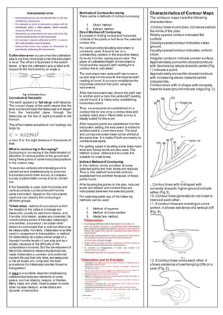
Collimationerror occurswhen the collimation
axis is not truly horizontalw hen the instrument
is level. The effect is illustrated in the sketch
below , w here the collimation axis is tilted w ith
respect to the horizontalby an angle a.
Curvature of the earth:
The earth appears to “fall away” with distance.
The curved shape of the earth means that the
level surface through the telescope w ill depart
from the horizontal plane through the
telescope as the line of sight proceeds to the
horizon.
This effect makes actuallevel rod readings too
large by:
w here D is the sight distance in thousands of
feet.
What is contouring in Surveying?
Contouring in surveying is the determination of
elevation of various points on the ground and
fixing these points of same horizontal positions
in the contour map.
To exercise verticalcontrolleveling w orkis
carried out and simultaneously to exercise
horizontalcontrolchain survey or compass
survey or plane table survey is to be carried
out.
If the theodolite is used, both horizontal and
verticalcontrols can be achieved fromthe
same instrument. Based on the instruments
used one can classify the contouring in
different groups.
Trilateration, method of surveying in w hich
the lengths of the sides of a triangle are
measured, usually by electronic means, and,
fromthis information, angles are computed. By
constructing a series of triangles adjacent to
one another, a surveyor can obtain other
distances and angles that w ould not otherw ise
be measurable. Formerly, trilateration w as little
used in comparison to triangulation, a method
for determining tw o sides and an angle of a
triangle fromthe length of one side and tw o
angles, because of the difficulty of the
computations involved. But the development of
electronic distance-measuring devices has
made trilateration a common and preferred
system. Except that only lines are measured,
w hile all angles are computed, the field
procedures for trilateration are like those for
triangulation.
A map is a symbolic depiction emphasizing
relationships betw een elements of some
space, such as objects, regions, or themes.
Many maps are static, fixed to paper or some
other durable medium, w hile others are
dynamic or interactive
Methods of Contour Surveying
There are tw o methods of contour surveying:
1. Direct method
2. Indirect method
Direct Methodof Contouring
It consists in finding verticaland horizontal
controls of the points w hich lie on the selected
contour line.
For verticalcontrollevelling instrument is
commonly used. A level is set on a
commanding position in the area after taking
fly levels fromthe nearby bench mark. The
plane of collimation/height of instrument is
found and the required staff reading for a
contour line is calculated.
The instrument man asks staff man to move
up and dow n in the area till the required staff
reading is found. A surveyor establishesthe
horizontalcontrolof that point using his
instruments.
After that instrument man directs the staff man
to another point w here the same staff reading
can be found. It is follow ed by establishing
horizontalcontrol.
Thus, severalpoints are established on a
contour line on one or tw o contour lines and
suitably noted dow n. Plane table survey is
ideally suited for this w ork.
After required points are established fromthe
instrument setting, the instrument is shifted to
another point to cover more area. The level
and survey instrument need not be shifted at
the same time. It is better if both are nearby to
communicate easily.
For getting speed in levelling some times hand
level and Abney levels are also used. This
method is slow , tedious but accurate. It is
suitable for small areas.
Indirect Methodof Contouring
In this method, levels are taken at some
selected points and their levels are reduced.
Thus in this method horizontalcontrolis
established first and then the levels of those
points found.
After locating the points on the plan, reduced
levels are marked and contour lines are
interpolated betw een the selected points.
For selecting points any of the follow ing
methods can be used:
1. Method of squares
2. Method of cross-section
3. Radial line method
Characteristics of Contour Maps
The contours maps have the following
characteristics:
1. Contour lines mustclose,notnecessarilyin
the limits ofthe plan.
2. Widely spaced contour indicates flat
surface.
3. Closelyspaced contour indicates steep
ground.
4. Equally spaced contour indicates uniform
slope.
5. Irregular contours indicate uneven surface.
6. Approximately concentric closed contours
with decreasing values towards centre (Fig.
1) indicate a pond.
7. Approximately concentric closed contours
with increasing values towards centre
indicate hills.
8. Contour lines with U-shape with convexity
towards lower ground indicate ridge (Fig.2).
Fig. 2
Fig. 3
9. Contour lines with V-shaped with
convexity towards higher ground indicate
valley (Fig.3).
10. Contour lines generallydo not meetor
intersecteach other.
11. If contour lines are meeting in some
portion,it shows existence ofa vertical cliff
(Fig. 4).
Fig. 4
12. If contour lines cross each other,it
shows existence ofoverhanging cliffs or a
cave (Fig. 5).
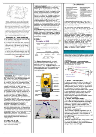
A GEOLOGICAL MAP is a map that is used to show
geological f eatures such as geologic strata and rock
units. The location of these f eatures underneath the
earth's surf ace are shown by sy mbols or colors.
Other f eatures such as f ault lines, f oliations, and f olds
are shown with strike and dip sy mbols which giv es
them a three-dimensional orientation. There are two
main ty pes of orientation measurements: orientation
of planes measured as “dip” and “strike” and
orientation of lines measured as “trend” and “plunge.”
Trend and plunge are sy mbolized by single arrows
and are used f or linear f eatures while strike and dip
are sy mbolized by a long strike line perpendicular to
the direction of the slope. In the US, geologic maps
are superimposed ov er topographic maps with
additional color masks with letters to represent a
geologic unit. In the UK, the term “geological map” is
used instead of “geologic map.
A CADASTER MAP is a map showing the real estate
of a country . It includes the location, area, ownership,
v alue, and tenure of an indiv idual parcel of land.
According to the International Federation of
Surv ey ors, a cadaster is an up-to-date land
inf ormation sy stem that contains records of interest of
lands such as restrictions, rights, and responsibilities.
It includes the geometric description of the land and
used alongside other records that describe the nature
of the interest, controls of such interest, and the v alue
of the parcel of land. Some maps also show
additional inf ormation such as parcel’s identif ication
number, surv ey district name, certificate of title
number, adjacent street names, and position of
existing structures.
DIFFRENTS TYPE OF EDM
MICRO WAVE INSTRUMENT
INFRA-RED WAVE INSTRUMENT
LIGHT WAVE INSTRUMENT
A TOPOGRAPHIC MAP is a ty pe of map that shows
large-scale detail and quantitativ e inf ormation of
relief by the use of contour lines and v arious other
methods. The map shows both human-made and
natural topographical f eatures. A topographical map
is based on a topographical surv ey that has been
perf ormed on large scale and shows v arieties of
elev ations and landf orms. Topographic maps hav e
v arious uses including geographical planning, civ il
engineering, large-scale architecture, and f or
recreation such as hiking. Features on the map are
usually represented by conv entional signs and
sy mbols. For instance, dif ferent colors can be used
to indicate the dif f erent classifications of roads. The
signs are usually explained just below the map or on
the margins. Apart f rom contour lines, topographic
maps also show f orest cov ers, water bodies, and
buildings.
A CITY MAP is a large-scale thematic map of
a city (or part of a city) created to enable the f astest
possible orientation in an urban space. The graphic
representation of objects on a city map is theref ore
usually greatly simplif ied, and reduced to generally
understood sy mbology .
M ODEL 3
The Distomat is a very small, compact
electronic distance measurement device,
particularly usefulin construction and
engineering w orks. The Distomat measures
distances smaller than 500 meters by simply
pointing the instrument to a reflector and
reading the result.
A satellite is an object in space that orbits or circles around a
bigger object. There are two kinds of satellites: natural (such as
the moon orbiting the Earth) or artificial (such as the International
Space Station orbiting the Earth).
Axis signal correction is the correction to be made to vertical
angle measured because of the difference between the height of
the instrument axis at the observer station and height of the
signal at the target station.
The sign of correction depends upon nature of vertical angle,
whether an angle of elevation or of depression
Refer the diagram given in Figure 1.2 of textbook (Volume 2)A is
the instrument stationB is the point at which staff is heldD is
the horizontal distance between themα is the observed angle
of inclinationS2 is the height of the staffS2 must be equal to
h1 i.e. the height of instrument, then the observed angle is the
true vertical angleIf not, then corrections have to be applied.
Let δ1 be the correction to be applied, thentan δ1 = (s2 –h1)
cos2α/DIf the vertical angle is very small, δ1 = (s2 –
h1)/Dsin1”If the observations are made from B towards A with β
as the observed vertical angle and δ2 then,tan δ1 = (s1 –h2)
cos2β /DThe axis signal correction is negative for an angle of
elevation and positive for an angle of depression.
Definition of reduction to center
The offset of a side auxiliary telescope requires a correction to observed
horizontal angles, and the offset of a top auxiliary telescope requires a
correction to observed vertical angles. The process of computing the
correct angle from the observed angle is called reduction to center.
THEODOLITE
W hich instrument is used in trigonometric levelling?
Explanation: Trigonometric levelling involves measurements
that are angular and hence requires an angle
measuring instrument, like theodolite
11. What is a Satellite station?
In order to have w ellconditioned triangles or for
better visibility, objects such as church spires,
flag poles, tow ers, etc. are some times selected
as triangulation stations. When the observations
are to be taken fromsuch a station, it is
impossible to set up an instrument over it. In such
a case, a subsidiary station, know n as satellite
station or eccentric station or false station is
selected as near to the main station and
observations are taken fromthe satellite station
and corrections applied.
12. What is reductionto center?
The angle measured fromsatellite stations has
to be corrected to w hat they would have been if
they w ere measured fromthe true station. The
operation of applying correction due to the
eccentricity of the station is generally know n as
reduction to center.
13. What is a bench mark?
Bench mark is a relatively permanent point of
reference whose elevation with respectto some
assumed datum is know n. It is used either as
starting point for leveling or as a point upon w hich
to close a check.
14. What is a Traveller?
A traveler is a specialtype of boning rod in w hich
the horizontalpieces can be moved along a
graduated verticalstaff, and can be conveniently
clamped at any desired height.
A microwave radiometer (MWR) is a radiometer
that measures energy emitted at millimetre-to-centimetre
wavelengths (frequencies of 1–1000 GHz) known
as microwaves. Microwave radiometers are very sensitive
receivers designed to measure thermal electromagnetic
radiation emitted by atmospheric gases.
Infrared W ave Instruments
Prism reflectors are used at the end of line to be measured.
These instruments are light and economical and can be
mounted on theodolite. With these instruments accuracy
achieved is ± 10 mm. The range of these instruments is up to
3 km.
The light wave instrument use visible or simply light
which means wave lengths that are visible to human eyes to
measure the distance. The measuring range of light wave
instruments is lesser that that of microwave instruments as
because of the less transmitting power of light wave
instruments. Here primary equipment is used as light wave
emitting instrument and corner cube prisms are used as
reflectors. When compare to the rest this method is more
cheap when compare the value of
instruments. Geodimeter falls under this type of instrument.
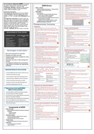
Photogrammetry- Surveying
Survey Principles Engineering Guide

More Related Content

What's hot

Compass surveying
Compass surveyingCompass surveying
Compass surveyingRAHUL SINHA
 
Compass survey part 1
Compass survey part 1Compass survey part 1
Compass survey part 1ArunRavi43
 
2.1 surveying, levelling and mapping
2.1 surveying, levelling and mapping2.1 surveying, levelling and mapping
2.1 surveying, levelling and mappingDigvijaysinh Gohil
 
types of bearing
types of bearingtypes of bearing
types of bearingankit5597
 
Compass surveying_Surveying, Civil Engineering
Compass surveying_Surveying, Civil EngineeringCompass surveying_Surveying, Civil Engineering
Compass surveying_Surveying, Civil EngineeringA Makwana
 
levelling and contouring
 levelling and  contouring levelling and  contouring
levelling and contouringAbdul Majid
 
Surveying and levelling
Surveying and levellingSurveying and levelling
Surveying and levellingParimal Jha
 
Fundamentals of surveying
Fundamentals of surveyingFundamentals of surveying
Fundamentals of surveyingSimonReuben2
 
Ce6304 surveying 1 contour (iv unit) lecture ppt notes
Ce6304 surveying 1   contour (iv unit) lecture ppt notesCe6304 surveying 1   contour (iv unit) lecture ppt notes
Ce6304 surveying 1 contour (iv unit) lecture ppt notesnandishsajjan
 
Civil engineering -jaja
Civil engineering -jajaCivil engineering -jaja
Civil engineering -jajajajaadolley
 
Compass surveying
Compass surveyingCompass surveying
Compass surveyingAhmed Eid
 
Contour lines - Survey & Levelling
Contour lines - Survey & LevellingContour lines - Survey & Levelling
Contour lines - Survey & LevellingAr. Avitesh
 
Theodolite surveying
Theodolite surveyingTheodolite surveying
Theodolite surveyingPhurba Tamang
 

What's hot (20)

Compass surveying
Compass surveyingCompass surveying
Compass surveying
 
Compass survey part 1
Compass survey part 1Compass survey part 1
Compass survey part 1
 
2.1 surveying, levelling and mapping
2.1 surveying, levelling and mapping2.1 surveying, levelling and mapping
2.1 surveying, levelling and mapping
 
Compass surveying
Compass surveyingCompass surveying
Compass surveying
 
types of bearing
types of bearingtypes of bearing
types of bearing
 
Compass surveying_Surveying, Civil Engineering
Compass surveying_Surveying, Civil EngineeringCompass surveying_Surveying, Civil Engineering
Compass surveying_Surveying, Civil Engineering
 
levelling and contouring
 levelling and  contouring levelling and  contouring
levelling and contouring
 
Plane Table Survey
Plane Table SurveyPlane Table Survey
Plane Table Survey
 
Surveying and levelling
Surveying and levellingSurveying and levelling
Surveying and levelling
 
Fundamentals of surveying
Fundamentals of surveyingFundamentals of surveying
Fundamentals of surveying
 
Compass Surveying
Compass SurveyingCompass Surveying
Compass Surveying
 
BEARING AND ITS TYPES
BEARING AND ITS TYPESBEARING AND ITS TYPES
BEARING AND ITS TYPES
 
Ce6304 surveying 1 contour (iv unit) lecture ppt notes
Ce6304 surveying 1   contour (iv unit) lecture ppt notesCe6304 surveying 1   contour (iv unit) lecture ppt notes
Ce6304 surveying 1 contour (iv unit) lecture ppt notes
 
Countering for surveying
Countering for surveyingCountering for surveying
Countering for surveying
 
Civil engineering -jaja
Civil engineering -jajaCivil engineering -jaja
Civil engineering -jaja
 
Compass surveying
Compass surveyingCompass surveying
Compass surveying
 
Contour lines - Survey & Levelling
Contour lines - Survey & LevellingContour lines - Survey & Levelling
Contour lines - Survey & Levelling
 
Theodolite surveying
Theodolite surveyingTheodolite surveying
Theodolite surveying
 
Contouring
ContouringContouring
Contouring
 
surveying contouring
surveying contouring surveying contouring
surveying contouring
 

Similar to Survey Principles Engineering Guide

1392741020 traverse survey
1392741020 traverse survey1392741020 traverse survey
1392741020 traverse surveyanjali adabala
 
traversing survey principles.docx
traversing survey principles.docxtraversing survey principles.docx
traversing survey principles.docxalexandermwaura
 
surveying-as.pptx
surveying-as.pptxsurveying-as.pptx
surveying-as.pptxAnshulSud1
 
fundamentals_of_surveying (2).pdf
fundamentals_of_surveying (2).pdffundamentals_of_surveying (2).pdf
fundamentals_of_surveying (2).pdfsandipanpaul16
 
Surveying & prismatic compass survey
Surveying & prismatic compass surveySurveying & prismatic compass survey
Surveying & prismatic compass surveySuman Das
 
1 fundamentals
1  fundamentals1  fundamentals
1 fundamentalsWaqas Khan
 
survey 12.pdf
survey 12.pdfsurvey 12.pdf
survey 12.pdfDarSafwan
 
Introduction to surveying, ranging and chaining
Introduction to surveying, ranging and chainingIntroduction to surveying, ranging and chaining
Introduction to surveying, ranging and chainingShital Navghare
 
coordinate systems map Projections and Atoms ppt - - Copy.pptx
coordinate systems map Projections  and Atoms ppt -  - Copy.pptxcoordinate systems map Projections  and Atoms ppt -  - Copy.pptx
coordinate systems map Projections and Atoms ppt - - Copy.pptxBakhtAli10
 
contouring.pptx
contouring.pptxcontouring.pptx
contouring.pptxSaiSrija7
 
overview and clasification of surveying ppt.pptx
overview and clasification of surveying ppt.pptxoverview and clasification of surveying ppt.pptx
overview and clasification of surveying ppt.pptxAshishJadhav655553
 
Theodolite seting up.pdf
Theodolite seting up.pdfTheodolite seting up.pdf
Theodolite seting up.pdfAlwandBarzani
 
PROJECTIONS & COORDINATE SYSTEMS-1.pptx
PROJECTIONS & COORDINATE SYSTEMS-1.pptxPROJECTIONS & COORDINATE SYSTEMS-1.pptx
PROJECTIONS & COORDINATE SYSTEMS-1.pptxSaitarunKuna
 
Aerial NAVIGATION and FLIGHT PLANNING.pptx
Aerial NAVIGATION and FLIGHT PLANNING.pptxAerial NAVIGATION and FLIGHT PLANNING.pptx
Aerial NAVIGATION and FLIGHT PLANNING.pptxEhtasham Amir
 

Similar to Survey Principles Engineering Guide (20)

1392741020 traverse survey
1392741020 traverse survey1392741020 traverse survey
1392741020 traverse survey
 
Fundamental Of Geodesy
Fundamental Of GeodesyFundamental Of Geodesy
Fundamental Of Geodesy
 
traversing survey principles.docx
traversing survey principles.docxtraversing survey principles.docx
traversing survey principles.docx
 
surveying-as.pptx
surveying-as.pptxsurveying-as.pptx
surveying-as.pptx
 
Introduction of Surveying
Introduction of Surveying Introduction of Surveying
Introduction of Surveying
 
Map reading
Map readingMap reading
Map reading
 
Field Astronomy
Field AstronomyField Astronomy
Field Astronomy
 
fundamentals_of_surveying (2).pdf
fundamentals_of_surveying (2).pdffundamentals_of_surveying (2).pdf
fundamentals_of_surveying (2).pdf
 
Surveying & prismatic compass survey
Surveying & prismatic compass surveySurveying & prismatic compass survey
Surveying & prismatic compass survey
 
1 fundamentals
1  fundamentals1  fundamentals
1 fundamentals
 
survey 12.pdf
survey 12.pdfsurvey 12.pdf
survey 12.pdf
 
navigation
navigationnavigation
navigation
 
Introduction to surveying, ranging and chaining
Introduction to surveying, ranging and chainingIntroduction to surveying, ranging and chaining
Introduction to surveying, ranging and chaining
 
coordinate systems map Projections and Atoms ppt - - Copy.pptx
coordinate systems map Projections  and Atoms ppt -  - Copy.pptxcoordinate systems map Projections  and Atoms ppt -  - Copy.pptx
coordinate systems map Projections and Atoms ppt - - Copy.pptx
 
Introduction to survey
Introduction to surveyIntroduction to survey
Introduction to survey
 
contouring.pptx
contouring.pptxcontouring.pptx
contouring.pptx
 
overview and clasification of surveying ppt.pptx
overview and clasification of surveying ppt.pptxoverview and clasification of surveying ppt.pptx
overview and clasification of surveying ppt.pptx
 
Theodolite seting up.pdf
Theodolite seting up.pdfTheodolite seting up.pdf
Theodolite seting up.pdf
 
PROJECTIONS & COORDINATE SYSTEMS-1.pptx
PROJECTIONS & COORDINATE SYSTEMS-1.pptxPROJECTIONS & COORDINATE SYSTEMS-1.pptx
PROJECTIONS & COORDINATE SYSTEMS-1.pptx
 
Aerial NAVIGATION and FLIGHT PLANNING.pptx
Aerial NAVIGATION and FLIGHT PLANNING.pptxAerial NAVIGATION and FLIGHT PLANNING.pptx
Aerial NAVIGATION and FLIGHT PLANNING.pptx
 

More from BIKIMALLIK1

Final plan with estimate sheet a1
Final plan with estimate sheet a1Final plan with estimate sheet a1
Final plan with estimate sheet a1BIKIMALLIK1
 
MAA SARASWATI PREPARED BY BIKI MALLIK
MAA SARASWATI PREPARED BY BIKI MALLIKMAA SARASWATI PREPARED BY BIKI MALLIK
MAA SARASWATI PREPARED BY BIKI MALLIKBIKIMALLIK1
 
PLAN DESIGN BY BIKI MALLIK
PLAN DESIGN BY BIKI MALLIKPLAN DESIGN BY BIKI MALLIK
PLAN DESIGN BY BIKI MALLIKBIKIMALLIK1
 
FIELD COMPACTION CE(PC)504
FIELD COMPACTION CE(PC)504FIELD COMPACTION CE(PC)504
FIELD COMPACTION CE(PC)504BIKIMALLIK1
 
Thiessen mean method
Thiessen mean methodThiessen mean method
Thiessen mean methodBIKIMALLIK1
 
Determination of alkalinity
Determination of alkalinityDetermination of alkalinity
Determination of alkalinityBIKIMALLIK1
 
Solid waste management
Solid waste managementSolid waste management
Solid waste managementBIKIMALLIK1
 
Assignment water demand
Assignment water demand Assignment water demand
Assignment water demand BIKIMALLIK1
 
Socal & global model 4
Socal & global model 4Socal & global model 4
Socal & global model 4BIKIMALLIK1
 
Ce(hs)401 model 2 & 3 all
Ce(hs)401  model 2 & 3 allCe(hs)401  model 2 & 3 all
Ce(hs)401 model 2 & 3 allBIKIMALLIK1
 
Nshm faculty of engineering & technology
Nshm faculty of engineering & technologyNshm faculty of engineering & technology
Nshm faculty of engineering & technologyBIKIMALLIK1
 
Management – I (Organizational Behaviour) Ce(mc)401 m3
Management – I (Organizational Behaviour) Ce(mc)401 m3Management – I (Organizational Behaviour) Ce(mc)401 m3
Management – I (Organizational Behaviour) Ce(mc)401 m3BIKIMALLIK1
 
Management – I (Organizational Behaviour) Ce(mc)401 m1
Management – I (Organizational Behaviour) Ce(mc)401 m1Management – I (Organizational Behaviour) Ce(mc)401 m1
Management – I (Organizational Behaviour) Ce(mc)401 m1BIKIMALLIK1
 

More from BIKIMALLIK1 (15)

Final plan with estimate sheet a1
Final plan with estimate sheet a1Final plan with estimate sheet a1
Final plan with estimate sheet a1
 
Cv
CvCv
Cv
 
MAA SARASWATI PREPARED BY BIKI MALLIK
MAA SARASWATI PREPARED BY BIKI MALLIKMAA SARASWATI PREPARED BY BIKI MALLIK
MAA SARASWATI PREPARED BY BIKI MALLIK
 
PLAN DESIGN BY BIKI MALLIK
PLAN DESIGN BY BIKI MALLIKPLAN DESIGN BY BIKI MALLIK
PLAN DESIGN BY BIKI MALLIK
 
FIELD COMPACTION CE(PC)504
FIELD COMPACTION CE(PC)504FIELD COMPACTION CE(PC)504
FIELD COMPACTION CE(PC)504
 
Thiessen mean method
Thiessen mean methodThiessen mean method
Thiessen mean method
 
Determination of alkalinity
Determination of alkalinityDetermination of alkalinity
Determination of alkalinity
 
EDM & GPS
EDM & GPSEDM & GPS
EDM & GPS
 
Solid waste management
Solid waste managementSolid waste management
Solid waste management
 
Assignment water demand
Assignment water demand Assignment water demand
Assignment water demand
 
Socal & global model 4
Socal & global model 4Socal & global model 4
Socal & global model 4
 
Ce(hs)401 model 2 & 3 all
Ce(hs)401  model 2 & 3 allCe(hs)401  model 2 & 3 all
Ce(hs)401 model 2 & 3 all
 
Nshm faculty of engineering & technology
Nshm faculty of engineering & technologyNshm faculty of engineering & technology
Nshm faculty of engineering & technology
 
Management – I (Organizational Behaviour) Ce(mc)401 m3
Management – I (Organizational Behaviour) Ce(mc)401 m3Management – I (Organizational Behaviour) Ce(mc)401 m3
Management – I (Organizational Behaviour) Ce(mc)401 m3
 
Management – I (Organizational Behaviour) Ce(mc)401 m1
Management – I (Organizational Behaviour) Ce(mc)401 m1Management – I (Organizational Behaviour) Ce(mc)401 m1
Management – I (Organizational Behaviour) Ce(mc)401 m1
 

Recently uploaded

Science 7 - LAND and SEA BREEZE and its Characteristics
Science 7 - LAND and SEA BREEZE and its CharacteristicsScience 7 - LAND and SEA BREEZE and its Characteristics
Science 7 - LAND and SEA BREEZE and its CharacteristicsKarinaGenton
 
“Oh GOSH! Reflecting on Hackteria's Collaborative Practices in a Global Do-It...
“Oh GOSH! Reflecting on Hackteria's Collaborative Practices in a Global Do-It...“Oh GOSH! Reflecting on Hackteria's Collaborative Practices in a Global Do-It...
“Oh GOSH! Reflecting on Hackteria's Collaborative Practices in a Global Do-It...Marc Dusseiller Dusjagr
 
Hybridoma Technology ( Production , Purification , and Application )
Hybridoma Technology  ( Production , Purification , and Application  ) Hybridoma Technology  ( Production , Purification , and Application  )
Hybridoma Technology ( Production , Purification , and Application ) Sakshi Ghasle
 
microwave assisted reaction. General introduction
microwave assisted reaction. General introductionmicrowave assisted reaction. General introduction
microwave assisted reaction. General introductionMaksud Ahmed
 
Introduction to AI in Higher Education_draft.pptx
Introduction to AI in Higher Education_draft.pptxIntroduction to AI in Higher Education_draft.pptx
Introduction to AI in Higher Education_draft.pptxpboyjonauth
 
Enzyme, Pharmaceutical Aids, Miscellaneous Last Part of Chapter no 5th.pdf
Enzyme, Pharmaceutical Aids, Miscellaneous Last Part of Chapter no 5th.pdfEnzyme, Pharmaceutical Aids, Miscellaneous Last Part of Chapter no 5th.pdf
Enzyme, Pharmaceutical Aids, Miscellaneous Last Part of Chapter no 5th.pdfSumit Tiwari
 
Kisan Call Centre - To harness potential of ICT in Agriculture by answer farm...
Kisan Call Centre - To harness potential of ICT in Agriculture by answer farm...Kisan Call Centre - To harness potential of ICT in Agriculture by answer farm...
Kisan Call Centre - To harness potential of ICT in Agriculture by answer farm...Krashi Coaching
 
KSHARA STURA .pptx---KSHARA KARMA THERAPY (CAUSTIC THERAPY)————IMP.OF KSHARA ...
KSHARA STURA .pptx---KSHARA KARMA THERAPY (CAUSTIC THERAPY)————IMP.OF KSHARA ...KSHARA STURA .pptx---KSHARA KARMA THERAPY (CAUSTIC THERAPY)————IMP.OF KSHARA ...
KSHARA STURA .pptx---KSHARA KARMA THERAPY (CAUSTIC THERAPY)————IMP.OF KSHARA ...M56BOOKSTORE PRODUCT/SERVICE
 
Incoming and Outgoing Shipments in 1 STEP Using Odoo 17
Incoming and Outgoing Shipments in 1 STEP Using Odoo 17Incoming and Outgoing Shipments in 1 STEP Using Odoo 17
Incoming and Outgoing Shipments in 1 STEP Using Odoo 17Celine George
 
Paris 2024 Olympic Geographies - an activity
Paris 2024 Olympic Geographies - an activityParis 2024 Olympic Geographies - an activity
Paris 2024 Olympic Geographies - an activityGeoBlogs
 
Presiding Officer Training module 2024 lok sabha elections
Presiding Officer Training module 2024 lok sabha electionsPresiding Officer Training module 2024 lok sabha elections
Presiding Officer Training module 2024 lok sabha electionsanshu789521
 
Introduction to ArtificiaI Intelligence in Higher Education
Introduction to ArtificiaI Intelligence in Higher EducationIntroduction to ArtificiaI Intelligence in Higher Education
Introduction to ArtificiaI Intelligence in Higher Educationpboyjonauth
 
ECONOMIC CONTEXT - LONG FORM TV DRAMA - PPT
ECONOMIC CONTEXT - LONG FORM TV DRAMA - PPTECONOMIC CONTEXT - LONG FORM TV DRAMA - PPT
ECONOMIC CONTEXT - LONG FORM TV DRAMA - PPTiammrhaywood
 
URLs and Routing in the Odoo 17 Website App
URLs and Routing in the Odoo 17 Website AppURLs and Routing in the Odoo 17 Website App
URLs and Routing in the Odoo 17 Website AppCeline George
 
Separation of Lanthanides/ Lanthanides and Actinides
Separation of Lanthanides/ Lanthanides and ActinidesSeparation of Lanthanides/ Lanthanides and Actinides
Separation of Lanthanides/ Lanthanides and ActinidesFatimaKhan178732
 
How to Make a Pirate ship Primary Education.pptx
How to Make a Pirate ship Primary Education.pptxHow to Make a Pirate ship Primary Education.pptx
How to Make a Pirate ship Primary Education.pptxmanuelaromero2013
 
Crayon Activity Handout For the Crayon A
Crayon Activity Handout For the Crayon ACrayon Activity Handout For the Crayon A
Crayon Activity Handout For the Crayon AUnboundStockton
 
Employee wellbeing at the workplace.pptx
Employee wellbeing at the workplace.pptxEmployee wellbeing at the workplace.pptx
Employee wellbeing at the workplace.pptxNirmalaLoungPoorunde1
 
Interactive Powerpoint_How to Master effective communication
Interactive Powerpoint_How to Master effective communicationInteractive Powerpoint_How to Master effective communication
Interactive Powerpoint_How to Master effective communicationnomboosow
 

Recently uploaded (20)

Science 7 - LAND and SEA BREEZE and its Characteristics
Science 7 - LAND and SEA BREEZE and its CharacteristicsScience 7 - LAND and SEA BREEZE and its Characteristics
Science 7 - LAND and SEA BREEZE and its Characteristics
 
“Oh GOSH! Reflecting on Hackteria's Collaborative Practices in a Global Do-It...
“Oh GOSH! Reflecting on Hackteria's Collaborative Practices in a Global Do-It...“Oh GOSH! Reflecting on Hackteria's Collaborative Practices in a Global Do-It...
“Oh GOSH! Reflecting on Hackteria's Collaborative Practices in a Global Do-It...
 
Hybridoma Technology ( Production , Purification , and Application )
Hybridoma Technology  ( Production , Purification , and Application  ) Hybridoma Technology  ( Production , Purification , and Application  )
Hybridoma Technology ( Production , Purification , and Application )
 
microwave assisted reaction. General introduction
microwave assisted reaction. General introductionmicrowave assisted reaction. General introduction
microwave assisted reaction. General introduction
 
Introduction to AI in Higher Education_draft.pptx
Introduction to AI in Higher Education_draft.pptxIntroduction to AI in Higher Education_draft.pptx
Introduction to AI in Higher Education_draft.pptx
 
Enzyme, Pharmaceutical Aids, Miscellaneous Last Part of Chapter no 5th.pdf
Enzyme, Pharmaceutical Aids, Miscellaneous Last Part of Chapter no 5th.pdfEnzyme, Pharmaceutical Aids, Miscellaneous Last Part of Chapter no 5th.pdf
Enzyme, Pharmaceutical Aids, Miscellaneous Last Part of Chapter no 5th.pdf
 
Kisan Call Centre - To harness potential of ICT in Agriculture by answer farm...
Kisan Call Centre - To harness potential of ICT in Agriculture by answer farm...Kisan Call Centre - To harness potential of ICT in Agriculture by answer farm...
Kisan Call Centre - To harness potential of ICT in Agriculture by answer farm...
 
TataKelola dan KamSiber Kecerdasan Buatan v022.pdf
TataKelola dan KamSiber Kecerdasan Buatan v022.pdfTataKelola dan KamSiber Kecerdasan Buatan v022.pdf
TataKelola dan KamSiber Kecerdasan Buatan v022.pdf
 
KSHARA STURA .pptx---KSHARA KARMA THERAPY (CAUSTIC THERAPY)————IMP.OF KSHARA ...
KSHARA STURA .pptx---KSHARA KARMA THERAPY (CAUSTIC THERAPY)————IMP.OF KSHARA ...KSHARA STURA .pptx---KSHARA KARMA THERAPY (CAUSTIC THERAPY)————IMP.OF KSHARA ...
KSHARA STURA .pptx---KSHARA KARMA THERAPY (CAUSTIC THERAPY)————IMP.OF KSHARA ...
 
Incoming and Outgoing Shipments in 1 STEP Using Odoo 17
Incoming and Outgoing Shipments in 1 STEP Using Odoo 17Incoming and Outgoing Shipments in 1 STEP Using Odoo 17
Incoming and Outgoing Shipments in 1 STEP Using Odoo 17
 
Paris 2024 Olympic Geographies - an activity
Paris 2024 Olympic Geographies - an activityParis 2024 Olympic Geographies - an activity
Paris 2024 Olympic Geographies - an activity
 
Presiding Officer Training module 2024 lok sabha elections
Presiding Officer Training module 2024 lok sabha electionsPresiding Officer Training module 2024 lok sabha elections
Presiding Officer Training module 2024 lok sabha elections
 
Introduction to ArtificiaI Intelligence in Higher Education
Introduction to ArtificiaI Intelligence in Higher EducationIntroduction to ArtificiaI Intelligence in Higher Education
Introduction to ArtificiaI Intelligence in Higher Education
 
ECONOMIC CONTEXT - LONG FORM TV DRAMA - PPT
ECONOMIC CONTEXT - LONG FORM TV DRAMA - PPTECONOMIC CONTEXT - LONG FORM TV DRAMA - PPT
ECONOMIC CONTEXT - LONG FORM TV DRAMA - PPT
 
URLs and Routing in the Odoo 17 Website App
URLs and Routing in the Odoo 17 Website AppURLs and Routing in the Odoo 17 Website App
URLs and Routing in the Odoo 17 Website App
 
Separation of Lanthanides/ Lanthanides and Actinides
Separation of Lanthanides/ Lanthanides and ActinidesSeparation of Lanthanides/ Lanthanides and Actinides
Separation of Lanthanides/ Lanthanides and Actinides
 
How to Make a Pirate ship Primary Education.pptx
How to Make a Pirate ship Primary Education.pptxHow to Make a Pirate ship Primary Education.pptx
How to Make a Pirate ship Primary Education.pptx
 
Crayon Activity Handout For the Crayon A
Crayon Activity Handout For the Crayon ACrayon Activity Handout For the Crayon A
Crayon Activity Handout For the Crayon A
 
Employee wellbeing at the workplace.pptx
Employee wellbeing at the workplace.pptxEmployee wellbeing at the workplace.pptx
Employee wellbeing at the workplace.pptx
 
Interactive Powerpoint_How to Master effective communication
Interactive Powerpoint_How to Master effective communicationInteractive Powerpoint_How to Master effective communication
Interactive Powerpoint_How to Master effective communication
 

Survey Principles Engineering Guide

  • 1. Surveying Principles Engineering Surveying is the process of determining relative positions of different objects on the surface of the earth by measuring horizontal distances betw een themand preparing a map to any suitable scale. Measurements are taken in horizontal plane only. Surveying is the art of determining the relative positions of points on, above or beneath the surface of the earth by means of direct or indirect measurements of distance, direction and elevation. Leveling is a branch of surveying the object of w hich is to find the elevations of points w ith respect to a given or assumed datum and to establish points at a given elevation or at different elevations with respectto a given or assumed datum. Survey is performed to prepare a map of relative positions on surface of the earth. It show sthe naturalfeature of a country such as tow ns, villages, roads, railways, etc. They may also include details of different engineering w orks such as bridge, canal, dam etc. Before commencement of any major engineering project, survey is carried out to determine the location of site and its surrounding. To understand the topography of the site and natural resource availability. Survey is carried out to prepare the cadastral map show ing propertyboundaries. Principles of Surveying The fundamental principle upon w hich the various methods of plane surveying are based can be stated under the follow ing two aspects. . Primary types of Surveying are:  Plane surveying  Geodetic surveying 1. Plane surveying Plane surveying is conducted by state agencies as w ellas private agencies. As we know earth is sphericalin shape but its diameter is big enough to consider plane in small dimensions. It is that type of surveying in w hich the mean surface of the earth is considered as a plane and the spheroidal shape is neglected. All triangles formed by survey lines are considered as plane triangles. The level line is considered as straight and plumb lines are considered parallel. Plane surveying is done of the area of survey is less than 250 km2 . 2. Geodetic surveying Geodetic surveyis conducted by survey department of the country. It is that type of surveying in w hich the curved shape of the earth is taken in to account. The object of geodetic survey is to determine the precise position on the surface of the earth, of a systemof w idely distant points w hich form controlstations in w hich surveysof less precision may be referred. . Line joining tw o points is considered as curved line and angles are assumed as sphericalangles. It is carried out if the area exceeds over 250 km2 a) Topographical Surveys They are carried out determine the position of natural features of a region such as rivers, streams, hills etc. and artificialfeatures such as roads and canals. The purpose of such surveys is to prepare maps and such maps of are called topo-sheets. b) Hydrographic Survey Hydro-graphic surveyis carried out to determine M.S.L. (Mean Sea Level), w ater spread area, depth of w ater bodies, velocityof flow in streams, cross-section area of flow etc. c) Astronomical Survey The AstronomicalSurvey is carried out to determine the absolute location of any point on the surface of earth. The survey consistsof making observations to heavenly bodies such as stars. d) Engineering Survey This type of survey is undertaken w henever sufficient data is to be collected for the purpose of planning and designing engineering w orks such as roads, bridges and reservoirs. Pythagorean Theorem In a right triangle, the square of the hypotenuse is equal to the sum of the squares of the other tw o sides. C 2 = A2 + B2 w here: Cis the hypotenuse (side opposite the right angle). A and B are the remaining sides. Units of Angular Measurement The most common angular units being employed in the United States is the Sexagesimal System. This systemuses angular notation in increments of 60 by dividing the circle into 360 degrees; degrees into 60 minutes; and minutes into 60 seconds. Therefore; 1 circle = 360° = 21,600´ = 1,296,000˝ 1° = 60´ = 3600˝ 1´ = 60 Meridian:A line on the mean surface of the earth joining the north and south poles. • Geographic North: True North Sometimes called Geodedic True North-fixed • Magnetic North: Taken froma magnetic compasschanges with time Grid North (Meridian): Lines parallel to a grid reference meridian (centralmeridian)- SPC Bearing - The direction of a line as given by the acute angle betw een the line and a reference meridian. Azimuth – The direction of a line as given by an angle measurement clockw ise (usually) fromthe north end of a reference meridian. (NAD 83 is fromthe North) (NAD 27 is from the South) Direct ranging can be done by 2 methods: DIRECT METHOD: This method is used w hen two ends of surveystations or survey lines are inter-visible. 1) RANGING BY EYE: Consider tw o pints X and Y w hich are inter-visible to each other. In this method ranging rod is fixed at station X and Y. Suppose if w e w ant to locate a point Z on ground w hich is in line w ith XY. The surveyor standshalf a metre backside of ranging rod at X in line w ith XY. Assistant then moves another ranging rod under the guidance of surveyor in such a w ay that ranging rod hold by assistant is in the line XY at point Z betw wen X ANDY. Similarly other points can be located by similar w ay. Surveyor has to guide assistant by using some hand signals so that ranging rod comes in the line.  INDIRECT RANGING: This method is used w hen two ends of survey stations or survey line are not inter-visible. Let X and Y be the 2 stations w hich are not inter- visible. So to proceed in straight line betw een X and Y process of indirect ranging is applied. Tw o intermediate points M1 and M2 are located in such a w ay that person standing w ith ranging rod at M2 can see M1 and X w hereasperson with ranging rod at M1 can see M2 and Y. Now person at M2 w illguide the person at M1 to come in line w ith M2 and X on a new position M3. Now the person at M3 w illguide the person at M2 to come to a new position M4 such that M3, M4 and Y are on same line. Ranging rod is fixed at M3 & M4 and chaining is continued along the hill. 2)RANGING BY LINE RANGER:Line ranger is a light and easy to use instrument w hich can be used for ranging. It consists of 2 plane mirrors or 2 right-angled isosceles prismplaces one above the another. Diagonals of tw o prism are silvered so as to reflect light. Low er prismis fixed w hile the upper prism is moveable. Instrument is provided w ith handle at bottom w hich gives ease to the user for using the instrument. Tw o ranging rods are fixed at inter-visible points. Then surveyor moves with the line ranger. The point w here two images coincide in line ranger is the point in line w ith two fixed ranging rods. At this point a pebble is dropped from the handle of line ranger and point is traced on ground. 2. Bearing • The bearing of a line is the horizontal angle w hich it makes w ith a reference line (meridian) depending upon the meridian, there are four types of bearings. True Bearing The true bearing of a line is the horizontal angle betw een the true meridian and the survey line. The true bearing is measured fromthe true north in the clockw ise direction. Magnetic Bearing The magnetic bearing of a line is the horizontalangle w hich the line makes w ith the magnetic north. 3. 22. Bearing Grid Bearing The grid bearing of a line is the horizontalangle w hich the line makes w ith the grid meridian. Arbitrary Bearing The arbitrary bearing of a line is the horizontal angle w hich the line makes w ith the arbitrary meridian 4. 25. Designation of Bearings • The bearing are designated in the follow ing two systems. • Whole Circle Bearing System (W.C.B) • Quadrantal Bearing System( Q.B.) 5. 26. Whole Circle Bearing System (W.C.B) • The bearing of a line measured w ith respect to magnetic meridian in clockw ise direction is called magnetic bearing and its value varies betw een0 0 to 360 0. • The Quadrants start fromNorth and Progress in a clockw ise direction as the first quadrant is 0 0 to 90 0 in clockw ise direction, 2nd 90 0 to 180 0 , 3 rd 180 0 to 270 0 , and up to 360 0 is 4th one. 6. 28. Whole Circle Bearing System (W.C.B) 7. 29. Quadrant Bearing System (Q.B.) • In this system, the bearing of survey lines are measured w ith respect to north line or south line w hich ever is the nearest to the given survey line and either in clockw ise direction or in anticlockw ise direction. • The bearing of lines w hich fallin Ist and IV th Quadrant are measured w ith respect to north line is nearer than south line, and bearing of lines fallin II nd and IIIrd quadrants are measured from south line as south is the nearer line. The surveyor’s compassmeasures the bearing of lines in the quadrant system.
  • 2. 1. 30. Reduced Bearing (RB) • When the whole circle bearing of a line is converted into quadrantal bearing itis termed as ‘Reduced Bearing’.Thus,the reduced bearing is similar to the quadrantal bearing.It’s value lies between 0 0 to 90 0, but the quadrants should be mentioned for proper designation. Levelling in surveying. Levelling is a process ofdetermining the heightofone level relative to another. It is used in surveying to establish the elevation of a pointrelative to a datum,or to establish a pointat a given elevation relative to a datum. Principle of levelling The principle of levelling is to obtain horizontal line of sightwith respectto which vertical distances ofthe points above or below this line of sightare found. Datum It is an arbitrary level surface from which elevation of points may be referred”. In India mean sea level is considered as datum ofzero elevation Mean sea level is the average heightof sea for all stages oftides it is derived by averaging the hourly tide heightover a period of 19 years. Elevation or Reduced level It is height or depth of any point above or below any datum.It is denoted as R.L. Bench Mark (B.M.) It is a fixed reference pointof known elevation with respectto datum. Line of collimation It is a line joining the intersection ofcross hairs of diaphragm to the optical centre of objectglass Height of instrumentand its continuation.It is also known as line of sight. It is the elevation of line of collimation with respectto datum Back sight It is a staff reading taken at a known elevation. It is the firststaff reading taken after setup of instrument. Fore sight( F.S.) It is the laststaff reading taken denoting the shifting ofthe instrument. Intermediate sight.(I.S.) It is staff reading taken on a pointwhose elevation is to be determined.All staff reading betweenB.S. and F.S. are Intermediate sight. Change Point It is a pointon which both fore and back sight are taken. What is Plane Table Surveying? The plane table surveying is the fast method of surveying. In this type of surveying plotting of the plan and field observations can be done simultaneously.In case of plane table surveying Geometrical conditions ofsite are manuscriptin the map sheetusing plane table and alidade after that topographic details are arranged on the map. General equipment used for conducting plane table survey are  Plane table  Alidade for sighting (telescopic or simple)  Plumb bob and plumb fork  Compass  Spirit level  Chain  Ranging rods  Tripod  Draw ing sheet and draw ing tools  Paper clips or screws Types of Levelingin Surveying 1. Direct leveling 2. Trigonometric leveling 3. Barometric leveling 4. Stadia leveling Differential Leveling Differentialleveling is performed w hen the distance betw een two points is more. In this process, number of inter stations are located and instrument is shifted to each station and observed the elevation of inter station points. Finally difference between originaltw o points is determined. Fly Leveling Fly leveling is conducted w hen the benchmark is very far fromthe w orkstation. In such case, a temporary bench mark is located at the w ork station w hich is located based on the original benchmark. Even it is not highly precise it is used for determining approximate level. Reciprocal Leveling When it is not possible to locate the leveling instrument in between theinter visible points,reciprocalleveling is performed.This case appears in case of pondsorrivers etc.in case ofreciprocal leveling,instrument is set nearerto 1st station andsightedtowards 2nd station. Trigonometric Leveling The process ofleveling in which the elevation of point orthe difference betweenpointsis measured fromthe observedhorizontal distances andverticalanglesin the field is called trigonometric leveling. What is Profile levelling? Profile leveling is one of the most common applications of running levels and vertical distance measurement for the surveyor. The results are plotted in the formof a profile, w hich is a draw ing that showsa verticalcrosssection. Profiles are required for the design and construction of roads, curbs, sidewalks, pipelines, etc. In short, profile leveling refers to the process of determining the elevation of points on the ground at mostly uniformintervals along a continuous line. Cross sectioning levelling Cross sectioning levelling is another method in profile levelling. The term cross-section generally refers to a relatively short profile view of the ground, w hich is drawn perpendicular to the route centerline of a highw ay or other types of linear projects. Cross-sectionaldrawingsare particularly important for estimating the earthw orkvolumes needed to construct a roadw ay; they show the existing ground elevations, the proposed cut or fill side slopes, and the grade elevation for the road base. There is really no difference in procedure betw een profile and cross-section leveling except for the form of the field notes. Cross-section rod shots are usually taken during the route profile survey fromthe same instrument positions used to take rod shots along the centerline. Errors in Levelling 1. InstrumentalErrors 2. Collimation Error 3. Error due to Curvature &Refraction
  • 3. Collimationerror occurswhen the collimation axis is not truly horizontalw hen the instrument is level. The effect is illustrated in the sketch below , w here the collimation axis is tilted w ith respect to the horizontalby an angle a. Curvature of the earth: The earth appears to “fall away” with distance. The curved shape of the earth means that the level surface through the telescope w ill depart from the horizontal plane through the telescope as the line of sight proceeds to the horizon. This effect makes actuallevel rod readings too large by: w here D is the sight distance in thousands of feet. What is contouring in Surveying? Contouring in surveying is the determination of elevation of various points on the ground and fixing these points of same horizontal positions in the contour map. To exercise verticalcontrolleveling w orkis carried out and simultaneously to exercise horizontalcontrolchain survey or compass survey or plane table survey is to be carried out. If the theodolite is used, both horizontal and verticalcontrols can be achieved fromthe same instrument. Based on the instruments used one can classify the contouring in different groups. Trilateration, method of surveying in w hich the lengths of the sides of a triangle are measured, usually by electronic means, and, fromthis information, angles are computed. By constructing a series of triangles adjacent to one another, a surveyor can obtain other distances and angles that w ould not otherw ise be measurable. Formerly, trilateration w as little used in comparison to triangulation, a method for determining tw o sides and an angle of a triangle fromthe length of one side and tw o angles, because of the difficulty of the computations involved. But the development of electronic distance-measuring devices has made trilateration a common and preferred system. Except that only lines are measured, w hile all angles are computed, the field procedures for trilateration are like those for triangulation. A map is a symbolic depiction emphasizing relationships betw een elements of some space, such as objects, regions, or themes. Many maps are static, fixed to paper or some other durable medium, w hile others are dynamic or interactive Methods of Contour Surveying There are tw o methods of contour surveying: 1. Direct method 2. Indirect method Direct Methodof Contouring It consists in finding verticaland horizontal controls of the points w hich lie on the selected contour line. For verticalcontrollevelling instrument is commonly used. A level is set on a commanding position in the area after taking fly levels fromthe nearby bench mark. The plane of collimation/height of instrument is found and the required staff reading for a contour line is calculated. The instrument man asks staff man to move up and dow n in the area till the required staff reading is found. A surveyor establishesthe horizontalcontrolof that point using his instruments. After that instrument man directs the staff man to another point w here the same staff reading can be found. It is follow ed by establishing horizontalcontrol. Thus, severalpoints are established on a contour line on one or tw o contour lines and suitably noted dow n. Plane table survey is ideally suited for this w ork. After required points are established fromthe instrument setting, the instrument is shifted to another point to cover more area. The level and survey instrument need not be shifted at the same time. It is better if both are nearby to communicate easily. For getting speed in levelling some times hand level and Abney levels are also used. This method is slow , tedious but accurate. It is suitable for small areas. Indirect Methodof Contouring In this method, levels are taken at some selected points and their levels are reduced. Thus in this method horizontalcontrolis established first and then the levels of those points found. After locating the points on the plan, reduced levels are marked and contour lines are interpolated betw een the selected points. For selecting points any of the follow ing methods can be used: 1. Method of squares 2. Method of cross-section 3. Radial line method Characteristics of Contour Maps The contours maps have the following characteristics: 1. Contour lines mustclose,notnecessarilyin the limits ofthe plan. 2. Widely spaced contour indicates flat surface. 3. Closelyspaced contour indicates steep ground. 4. Equally spaced contour indicates uniform slope. 5. Irregular contours indicate uneven surface. 6. Approximately concentric closed contours with decreasing values towards centre (Fig. 1) indicate a pond. 7. Approximately concentric closed contours with increasing values towards centre indicate hills. 8. Contour lines with U-shape with convexity towards lower ground indicate ridge (Fig.2). Fig. 2 Fig. 3 9. Contour lines with V-shaped with convexity towards higher ground indicate valley (Fig.3). 10. Contour lines generallydo not meetor intersecteach other. 11. If contour lines are meeting in some portion,it shows existence ofa vertical cliff (Fig. 4). Fig. 4 12. If contour lines cross each other,it shows existence ofoverhanging cliffs or a cave (Fig. 5).
  • 4. A GEOLOGICAL MAP is a map that is used to show geological f eatures such as geologic strata and rock units. The location of these f eatures underneath the earth's surf ace are shown by sy mbols or colors. Other f eatures such as f ault lines, f oliations, and f olds are shown with strike and dip sy mbols which giv es them a three-dimensional orientation. There are two main ty pes of orientation measurements: orientation of planes measured as “dip” and “strike” and orientation of lines measured as “trend” and “plunge.” Trend and plunge are sy mbolized by single arrows and are used f or linear f eatures while strike and dip are sy mbolized by a long strike line perpendicular to the direction of the slope. In the US, geologic maps are superimposed ov er topographic maps with additional color masks with letters to represent a geologic unit. In the UK, the term “geological map” is used instead of “geologic map. A CADASTER MAP is a map showing the real estate of a country . It includes the location, area, ownership, v alue, and tenure of an indiv idual parcel of land. According to the International Federation of Surv ey ors, a cadaster is an up-to-date land inf ormation sy stem that contains records of interest of lands such as restrictions, rights, and responsibilities. It includes the geometric description of the land and used alongside other records that describe the nature of the interest, controls of such interest, and the v alue of the parcel of land. Some maps also show additional inf ormation such as parcel’s identif ication number, surv ey district name, certificate of title number, adjacent street names, and position of existing structures. DIFFRENTS TYPE OF EDM MICRO WAVE INSTRUMENT INFRA-RED WAVE INSTRUMENT LIGHT WAVE INSTRUMENT A TOPOGRAPHIC MAP is a ty pe of map that shows large-scale detail and quantitativ e inf ormation of relief by the use of contour lines and v arious other methods. The map shows both human-made and natural topographical f eatures. A topographical map is based on a topographical surv ey that has been perf ormed on large scale and shows v arieties of elev ations and landf orms. Topographic maps hav e v arious uses including geographical planning, civ il engineering, large-scale architecture, and f or recreation such as hiking. Features on the map are usually represented by conv entional signs and sy mbols. For instance, dif ferent colors can be used to indicate the dif f erent classifications of roads. The signs are usually explained just below the map or on the margins. Apart f rom contour lines, topographic maps also show f orest cov ers, water bodies, and buildings. A CITY MAP is a large-scale thematic map of a city (or part of a city) created to enable the f astest possible orientation in an urban space. The graphic representation of objects on a city map is theref ore usually greatly simplif ied, and reduced to generally understood sy mbology . M ODEL 3 The Distomat is a very small, compact electronic distance measurement device, particularly usefulin construction and engineering w orks. The Distomat measures distances smaller than 500 meters by simply pointing the instrument to a reflector and reading the result. A satellite is an object in space that orbits or circles around a bigger object. There are two kinds of satellites: natural (such as the moon orbiting the Earth) or artificial (such as the International Space Station orbiting the Earth). Axis signal correction is the correction to be made to vertical angle measured because of the difference between the height of the instrument axis at the observer station and height of the signal at the target station. The sign of correction depends upon nature of vertical angle, whether an angle of elevation or of depression Refer the diagram given in Figure 1.2 of textbook (Volume 2)A is the instrument stationB is the point at which staff is heldD is the horizontal distance between themα is the observed angle of inclinationS2 is the height of the staffS2 must be equal to h1 i.e. the height of instrument, then the observed angle is the true vertical angleIf not, then corrections have to be applied. Let δ1 be the correction to be applied, thentan δ1 = (s2 –h1) cos2α/DIf the vertical angle is very small, δ1 = (s2 – h1)/Dsin1”If the observations are made from B towards A with β as the observed vertical angle and δ2 then,tan δ1 = (s1 –h2) cos2β /DThe axis signal correction is negative for an angle of elevation and positive for an angle of depression. Definition of reduction to center The offset of a side auxiliary telescope requires a correction to observed horizontal angles, and the offset of a top auxiliary telescope requires a correction to observed vertical angles. The process of computing the correct angle from the observed angle is called reduction to center. THEODOLITE W hich instrument is used in trigonometric levelling? Explanation: Trigonometric levelling involves measurements that are angular and hence requires an angle measuring instrument, like theodolite 11. What is a Satellite station? In order to have w ellconditioned triangles or for better visibility, objects such as church spires, flag poles, tow ers, etc. are some times selected as triangulation stations. When the observations are to be taken fromsuch a station, it is impossible to set up an instrument over it. In such a case, a subsidiary station, know n as satellite station or eccentric station or false station is selected as near to the main station and observations are taken fromthe satellite station and corrections applied. 12. What is reductionto center? The angle measured fromsatellite stations has to be corrected to w hat they would have been if they w ere measured fromthe true station. The operation of applying correction due to the eccentricity of the station is generally know n as reduction to center. 13. What is a bench mark? Bench mark is a relatively permanent point of reference whose elevation with respectto some assumed datum is know n. It is used either as starting point for leveling or as a point upon w hich to close a check. 14. What is a Traveller? A traveler is a specialtype of boning rod in w hich the horizontalpieces can be moved along a graduated verticalstaff, and can be conveniently clamped at any desired height.
  • 5. A microwave radiometer (MWR) is a radiometer that measures energy emitted at millimetre-to-centimetre wavelengths (frequencies of 1–1000 GHz) known as microwaves. Microwave radiometers are very sensitive receivers designed to measure thermal electromagnetic radiation emitted by atmospheric gases. Infrared W ave Instruments Prism reflectors are used at the end of line to be measured. These instruments are light and economical and can be mounted on theodolite. With these instruments accuracy achieved is ± 10 mm. The range of these instruments is up to 3 km. The light wave instrument use visible or simply light which means wave lengths that are visible to human eyes to measure the distance. The measuring range of light wave instruments is lesser that that of microwave instruments as because of the less transmitting power of light wave instruments. Here primary equipment is used as light wave emitting instrument and corner cube prisms are used as reflectors. When compare to the rest this method is more cheap when compare the value of instruments. Geodimeter falls under this type of instrument. Photogrammetry- Surveying