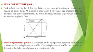
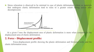
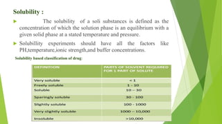
The document discusses various techniques to enhance the solubility and dissolution rate of poorly soluble drugs, including physical and chemical modifications. Some key points:
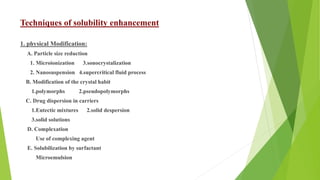
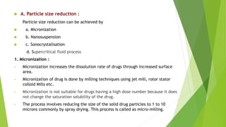
1. Physical modifications like particle size reduction through micronization, nanosuspensions, and sonocrystallization can increase surface area and solubility. Other methods are polymorphism, solid dispersions, and complexation.
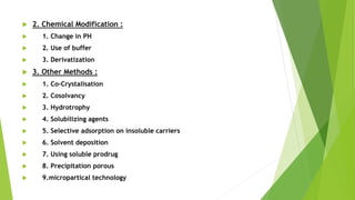
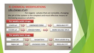
2. Chemical modifications involve changing pH, adding buffers, or derivatizing drugs.
3. Other solubility enhancement methods discussed are co-crystallization, cosolvency, hydrotrophy, solubilizing agents, and using soluble prodrugs. Compaction analysis and different compaction profiles are also summarized.


![Physics_of_Tablet_Compression_MP_PPT[1].pptx](https://cdn.slidesharecdn.com/ss_thumbnails/physicsoftabletcompressionmpppt1-250617142628-a6154203-thumbnail.jpg?width=640&height=640&fit=bounds)


