This document discusses collision detection and reaction strategies for robots. It covers:
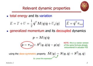
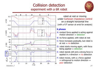
1. Methods for detecting collisions using proprioceptive sensors like measuring variations in control torques, joint accelerations, or monitoring total robot energy.
2. Strategies for isolating where collisions occur on the robot's links using momentum-based residuals.
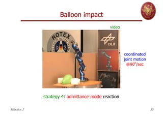
3. Different reaction strategies robots can employ after detecting collisions, like stopping motion, using reflexive or admittance control, preserving tasks using redundancy, or combining multiple strategies.
4. Experiments demonstrating these methods on robots with rigid and elastic joints like the DLR LWR-III, detecting impacts from objects like a dummy head or balloons and comparing reaction strategies.


![HRI/HRC in closed control architectures
KUKA KR5 Sixx R650 robot
Robotics 2 44
§ low-level control laws are not known nor accessible by
the user: no current or torque commands can be used
§ user programs, based also on other exteroceptive
sensors (vision, Kinect, F/T sensor) can be implemented
on an external PC via the RSI (RobotSensorInterface),
communicating with the KUKA controller every 12 ms
§ robot measures available to the user: joint positions (by
encoders) and [absolute value of] motor currents
§ controller reference is given as a velocity or a position
in joint space (also Cartesian commands are accepted)
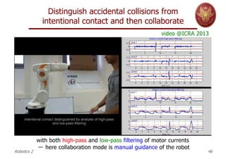
motor currents measured
on first three joints](https://image.slidesharecdn.com/collisiondetectionreaction-230104163859-fd1fa3f6/85/CollisionDetectionReaction-pdf-44-320.jpg)