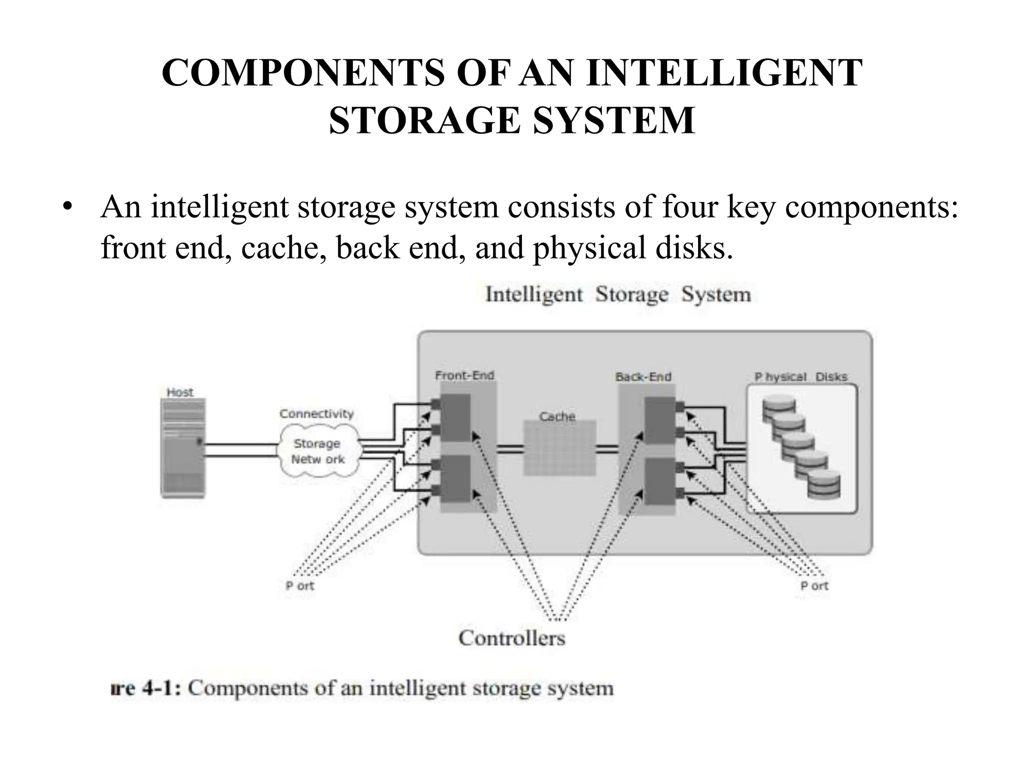
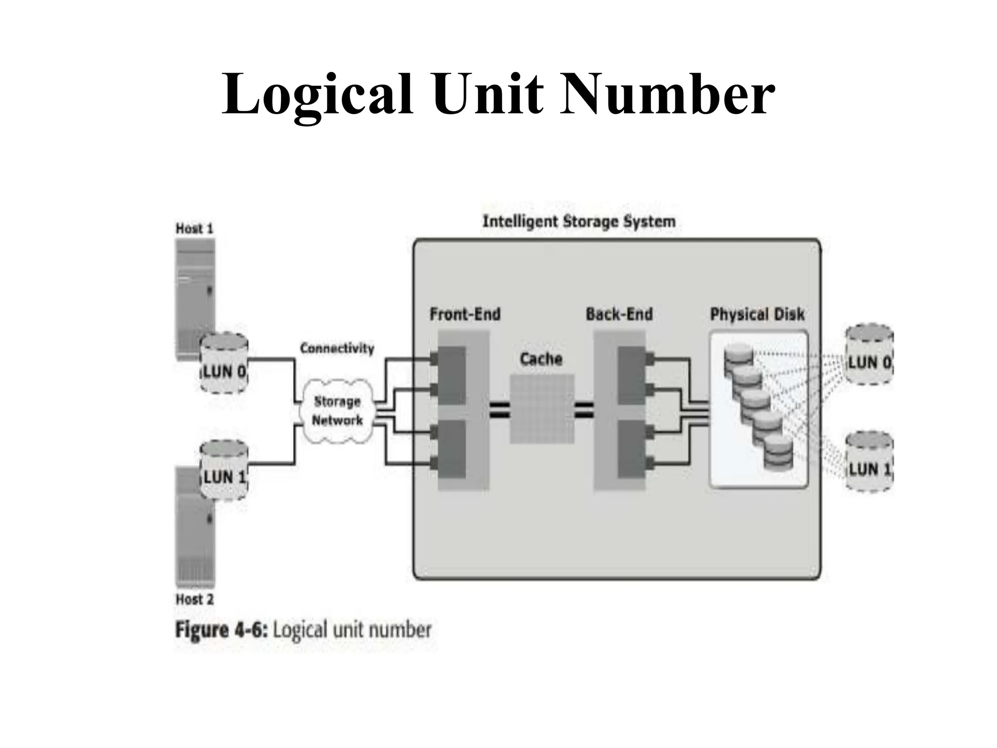
The document discusses intelligent storage systems, emphasizing their key components: front end, cache, back end, and physical disks, which together enhance performance, availability, and reliability in storage solutions. It delves into the mechanics of command queuing, cache operations, and the importance of efficient cache management to optimize I/O performance. Additionally, it covers RAID technologies, logical unit numbers, and the architecture of physical disk drives.
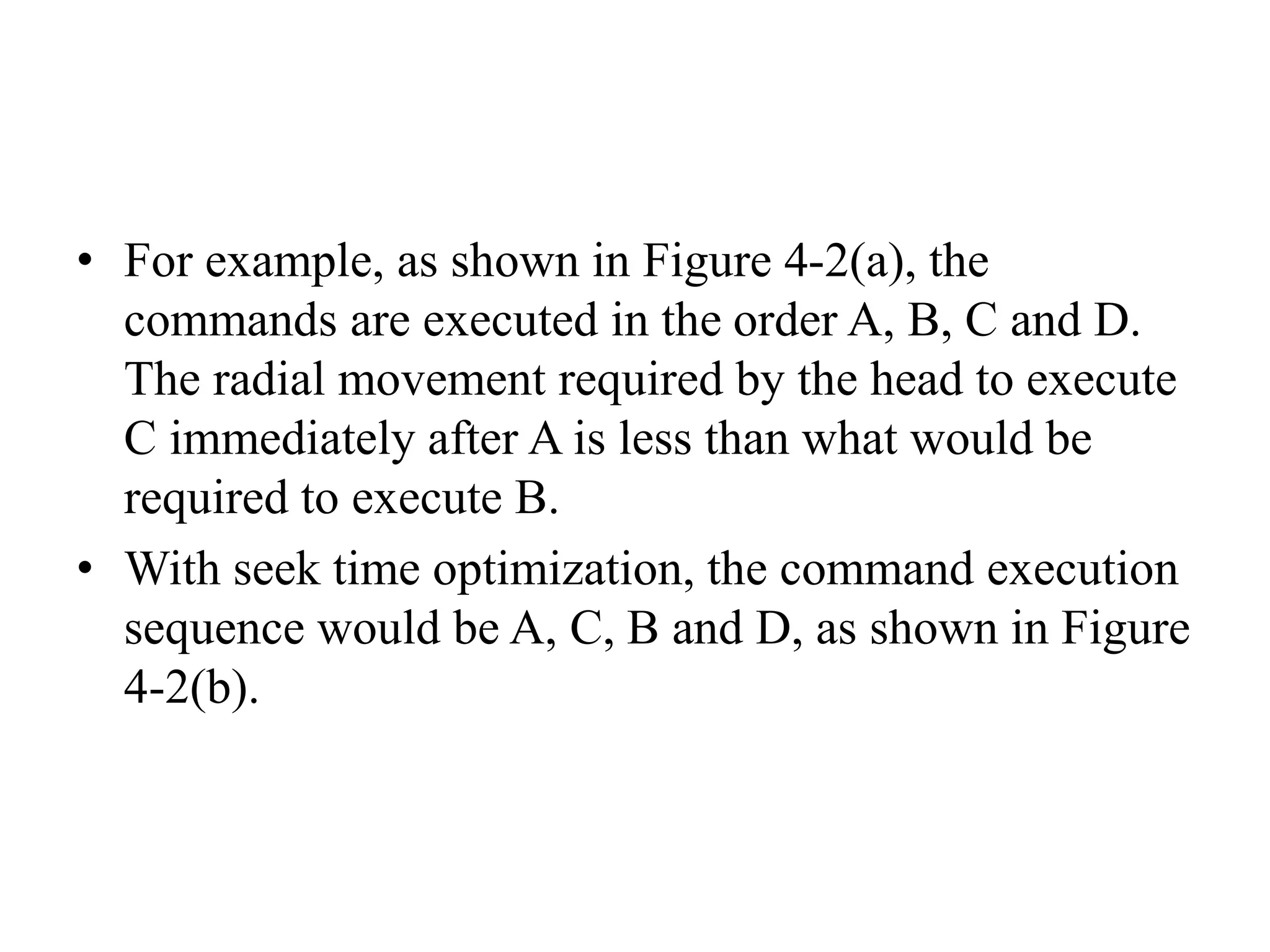
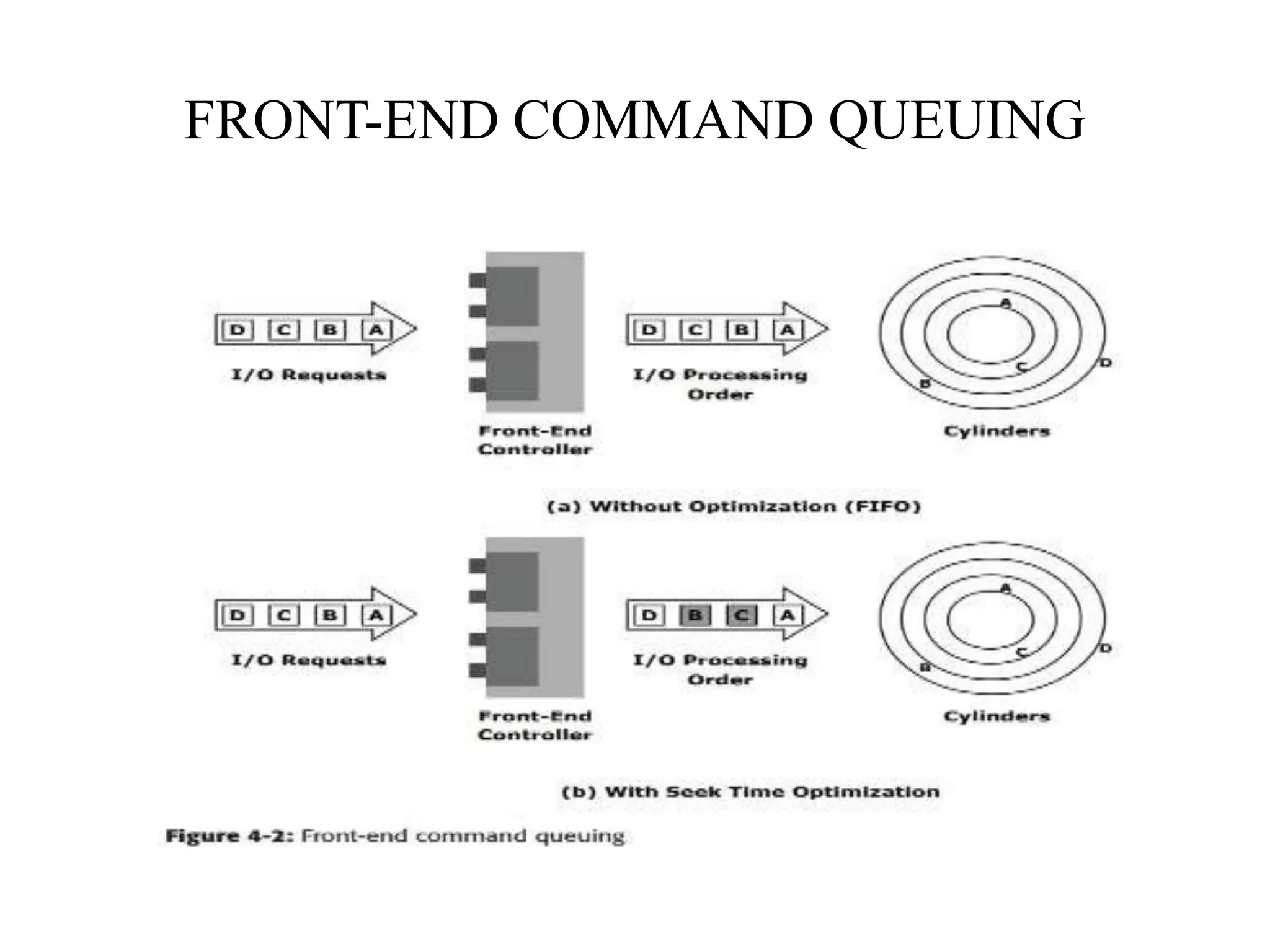
![command queuing algorithms
• First In First Out (FIFO): This is the default
algorithm where commands are executed in the order in
which they are received (Figure 4-2 [a]). There is no
reordering of requests for optimization; therefore, it is
inefficient in terms of performance.
• Seek Time Optimization: Commands are executed
based on optimizing read/write head movements, which
may result in reordering of commands. Without seek
time optimization, the commands are executed in the
order they are received.](https://image.slidesharecdn.com/unitiiintelligentstoragesystemsandraid-240703092023-1b4e782c/75/UNIT-II-INTELLIGENT-STORAGE-SYSTEMS-AND-RAID-pptx-9-2048.jpg)
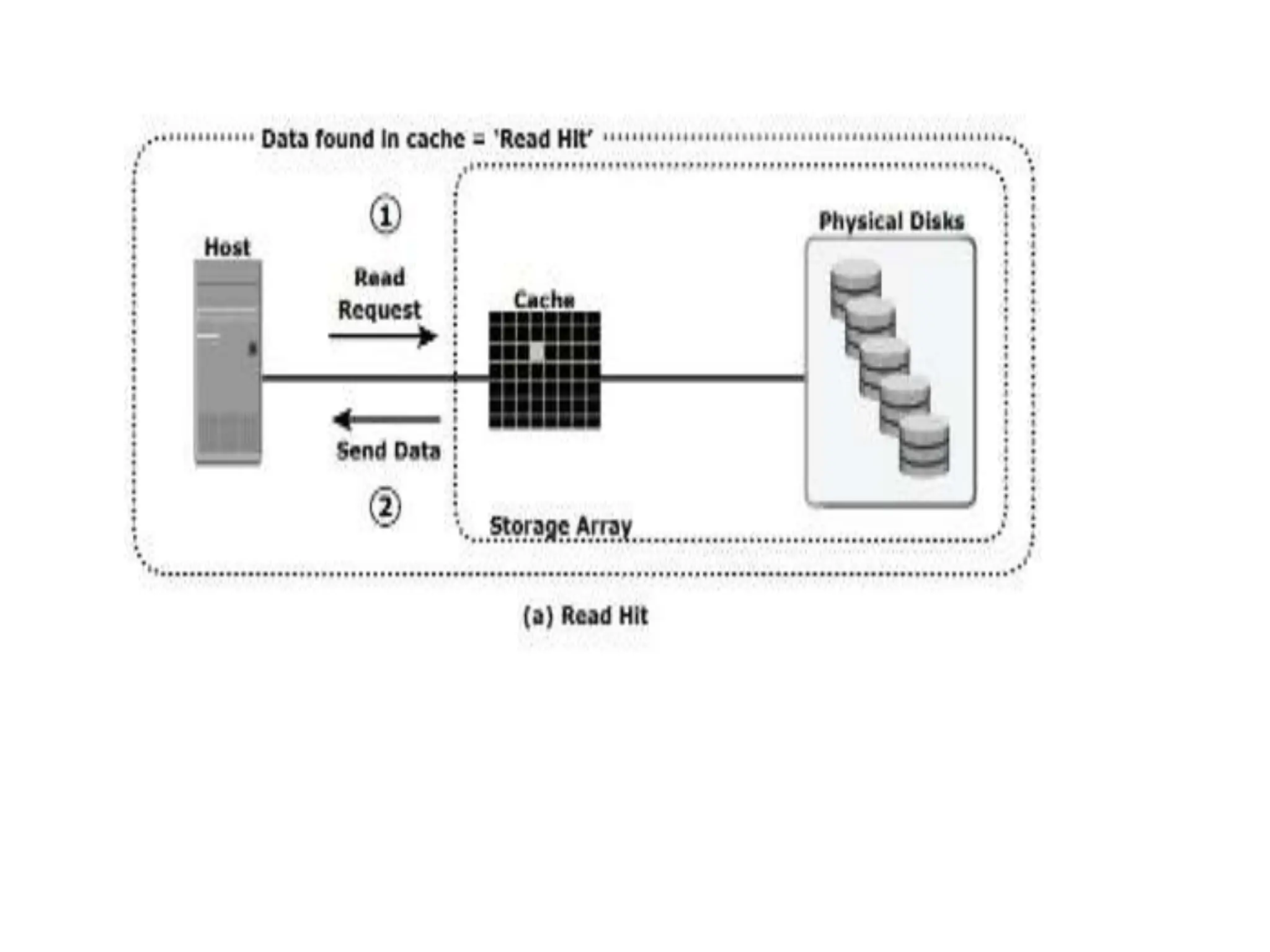
![READ OPERATION WITH CACHE
• When a host issues a read request, the front-
end controller accesses the tag RAM to
determine whether the required data is available
in cache.
• If the requested data is found in the cache, it is
called a read cache hit or read hit and data is sent
directly to the host, without any disk operation
(see Figure 4-4[a]).This provides a fast response
time to the host (about a millisecond).](https://image.slidesharecdn.com/unitiiintelligentstoragesystemsandraid-240703092023-1b4e782c/75/UNIT-II-INTELLIGENT-STORAGE-SYSTEMS-AND-RAID-pptx-18-2048.jpg)
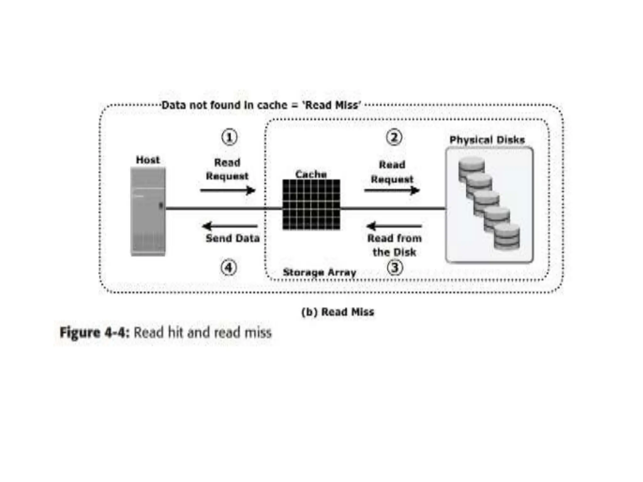
![ If the requested data is not found in cache, it is called a cache
miss and the data must be read from the disk (see Figure 4-
4[b]).
The back-end controller accesses the appropriate disk and
retrieves the requested data. Data is then placed in cache and is
finally sent to the host through the frontend controller.
Cache misses increase I/O response time.
A pre-fetch, or read-ahead, algorithm is used when read
requests are sequential. In a sequential read request, a
contiguous set of associated blocks is retrieved.
Several other blocks that have not yet been requested by the
host can be read from the disk and placed into cache in
advance.](https://image.slidesharecdn.com/unitiiintelligentstoragesystemsandraid-240703092023-1b4e782c/75/UNIT-II-INTELLIGENT-STORAGE-SYSTEMS-AND-RAID-pptx-20-2048.jpg)
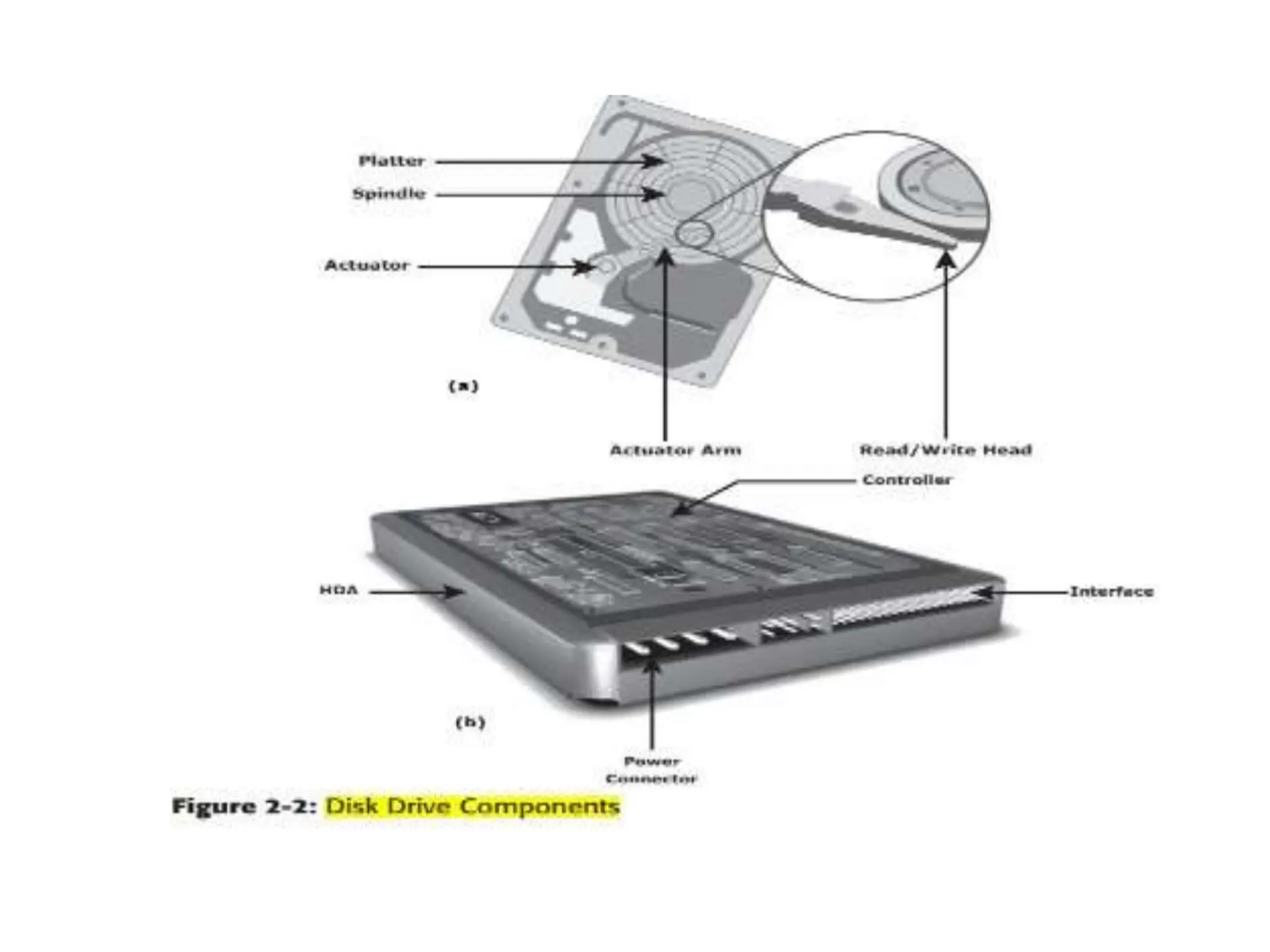
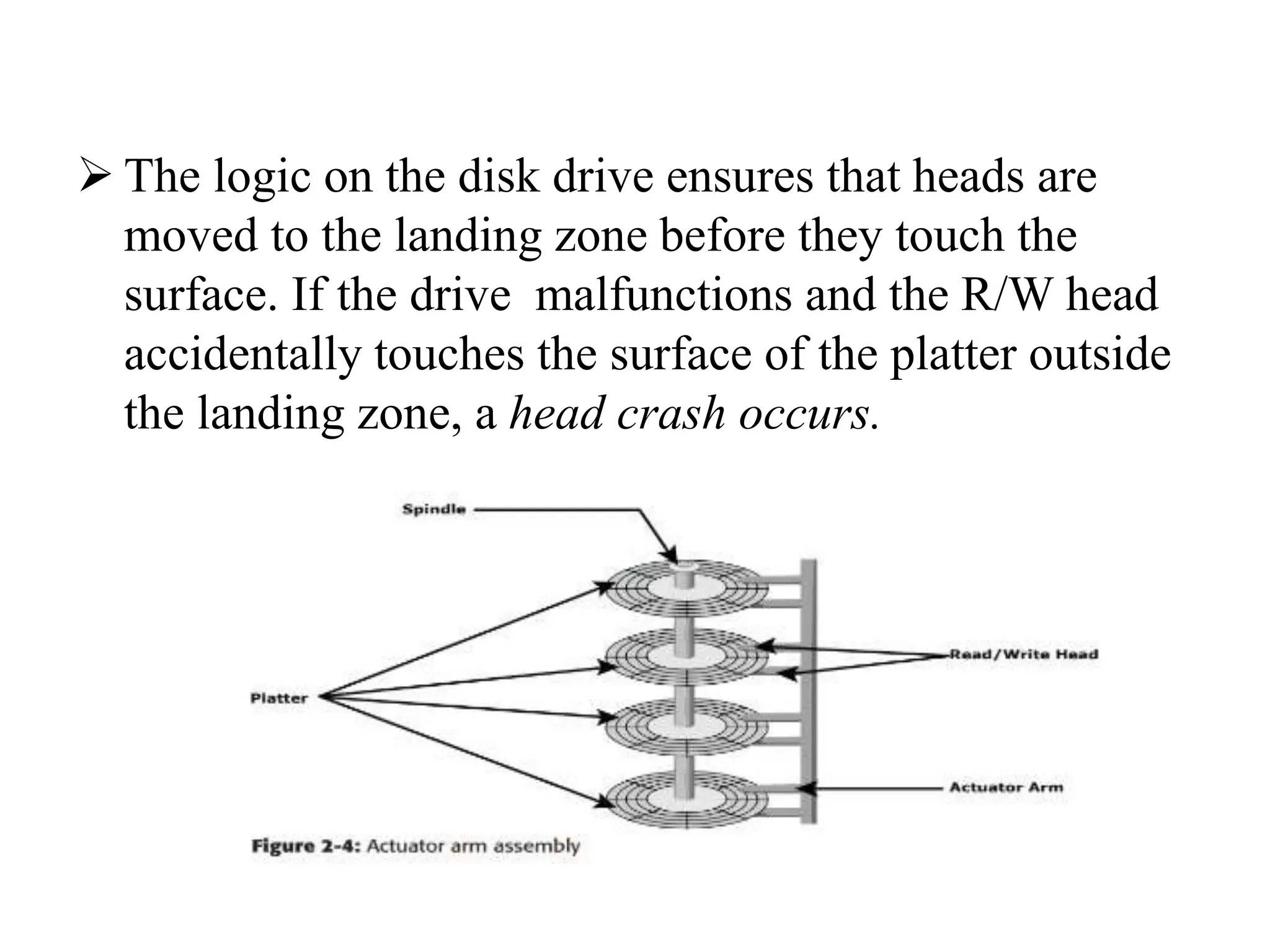
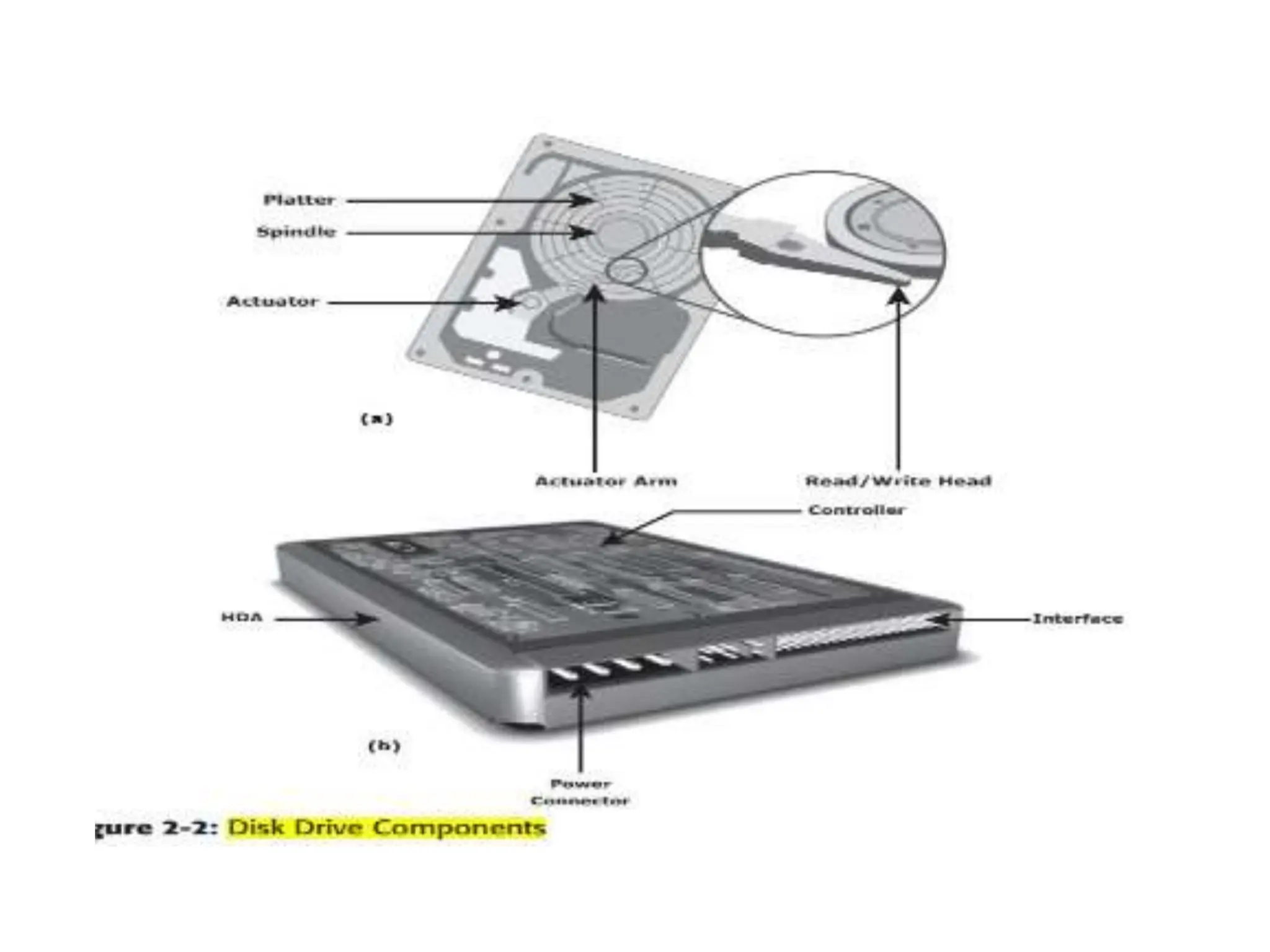
![ACTIVATOR ARM ASSEMBLY
The R/W heads are mounted on the actuator
arm assembly (refer to Figure 2-2 [a]),which
positions the R/W head at the location on the
platter where the data needs to be written or
read. The R/W heads for all platters on a drive
are attached to one actuator arm assembly
and move across the platters simultaneously.](https://image.slidesharecdn.com/unitiiintelligentstoragesystemsandraid-240703092023-1b4e782c/75/UNIT-II-INTELLIGENT-STORAGE-SYSTEMS-AND-RAID-pptx-47-2048.jpg)
![CONTROLLER
• The controller (see Figure 2-2 [b]) is a printed circuit
board, mounted at the bot- tom of a disk drive. It
consists of a microprocessor, internal memory,circuitry,
and firmware.
• The firmware controls power to the spindle motor
and the speed of the motor. It also manages
communication between the drive and the host.
• In addition, it controls the R/W operations by moving
the actuator arm and switching between different R/W
heads, and performs the optimization of data access.](https://image.slidesharecdn.com/unitiiintelligentstoragesystemsandraid-240703092023-1b4e782c/75/UNIT-II-INTELLIGENT-STORAGE-SYSTEMS-AND-RAID-pptx-48-2048.jpg)