Downloaded 200 times

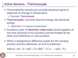
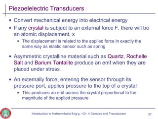
![Resistive Sensors – Temperature Dependent Resistors
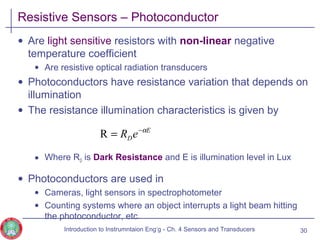
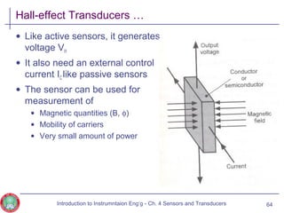
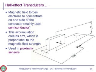
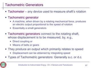
• Two classes of thermal resistors are
• Metallic element
• Semiconductor
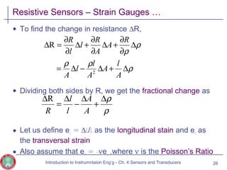
• For most metals, the resistance increases with increase in
temperature
• Where α is the temperature coefficient of resistance and given as
• Example: Platinum
• Has a linear temperature-resistance characteristics
• Reproducible over a wide range of temperature
• Platinum Thermometers are used for temperature measurement
22
]1[...]1[)(R 0
2
210 TRTTRT ααα +≈+++=
0
1
R
R
T
∆
∆
=α
Introduction to Instrumntaion Eng‘g - Ch. 4 Sensors and Transducers](https://image.slidesharecdn.com/cn3-sensorsandtransducers-1-141227124235-conversion-gate01/85/Cn3-sensors-and-transducers-1-22-320.jpg)


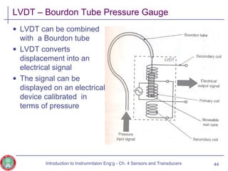
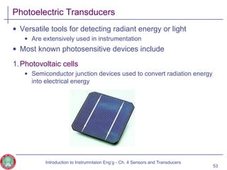


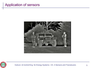
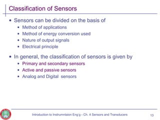
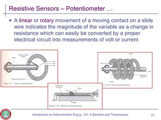
This document discusses different types of sensors and transducers. It begins with an introduction to sensors, defining them as devices that convert non-electrical quantities into electrical signals. It then covers various classifications of sensors including primary/secondary, active/passive, and analog/digital. Specific types of sensors are described in more detail, including resistive sensors such as potentiometers, temperature dependent resistors, and strain gauges. Capacitive and inductive sensors are also briefly mentioned. The document provides examples and equations to explain the functioning and properties of different sensors.