SlideShare a Scribd company logo
1 of 33
Download to read offline
UNIT-III
Clutches ,Brakes and Dynamometer
Friction Clutches
A friction clutch has its principal application in the transmission of power of
shafts and machines which must be started and stopped frequently. Its application is also
found in cases in which power is to be delivered to machines partially or fully loaded.
The force of friction is used to start the driven shaft from rest and gradually brings it up
to the proper speed without excessive slipping of the friction surfaces. In automobiles,
friction clutch is used to connect the engine to the driven shaft. In operating such a clutch,
care should be taken so that the friction surfaces engage easily and gradually brings the
driven shaft up to proper speed. The proper alignment of the bearing must be maintained
and it should be located as close to the clutch as possible. It may be noted that
1. The contact surfaces should develop a frictional force that may pick up and hold the
load with reasonably low pressure between the contact surfaces.
2. The heat of friction should be rapidly dissipated and tendency to grab should be at a
minimum.
3. The surfaces should be backed by a material stiff enough to ensure a reasonably
uniform distribution of pressure.
The friction clutches of the following types are important from the subject point of view :
1. Disc or plate clutches (single disc or multiple disc clutch),
2. Cone clutches, and
3. Centrifugal clutches.
We shall now discuss, these clutches, in detail, in the following pages. It may be noted
that the disc and cone clutches are based on the same theory as the pivot and collar
bearings.
Single Disc or Plate Clutch:
A single disc or plate clutch, as shown in Fig., consists of a clutch plate whose
both sides are faced with a friction material (usually of Ferrodo). It is mounted on the hub
which is free to move axially along the splines of the driven shaft. The pressure plate is
mounted inside the clutch body which is bolted to the flywheel. Both the pressure plate
and the flywheel rotate with the engine crankshaft or the driving shaft. The pressure plate
pushes the clutch plate towards the flywheel by a set of strong springs which are arranged
radially inside the body. The three levers (also known as release levers or fingers) are
carried on pivots suspended from the case of the body. These are arranged in such a
manner so that the pressure plate moves away from the flywheel by the inward movement
of a thrust bearing. The bearing is mounted upon a forked shaft and moves forward when
the clutch pedal is pressed. When the clutch pedal is pressed down, its linkage forces the
thrust release bearing to move in towards the flywheel and pressing the longer ends of
the levers inward. The levers are forced to turn on their suspended pivot and the pressure
plate moves away from the flywheel by the knife edges, thereby compressing the clutch
springs. This action removes the pressure from the clutch plate and thus moves back from
the flywheel and the driven shaft becomes stationary. On the other hand, when the foot is
taken off from the clutch pedal, the thrust bearing moves back by the levers. This allows
the springs to extend and thus the pressure plate pushes the clutch plate back towards the
flywheel.
The axial pressure exerted by the spring provides a frictional force in the circumferential
direction when the relative motion between the driving and driven members tends to take
place. If the torque due to this frictional force exceeds the torque to be transmitted, then
no slipping takes place and the power is transmitted from the driving shaft to the driven
shaft.
Now consider two friction surfaces, maintained in contact by an axial thrust W, as shown
in Fig. (a).
Let
T = Torque transmitted by the clutch,
p = Intensity of axial pressure with which the contact surfaces are held together,
r1 and r2 = External and internal radii of friction faces, and
µ = Coefficient of friction.
Consider an elementary ring of radius r and thickness dr as shown in Fig. (b).
We know that area of contact surface or friction surface, = 2 π r.dr
Normal or axial force on the ring,
δW = Pressure × Area = p × 2 π r.dr
and the frictional force on the ring acting tangentially at radius r,
Fr = µ.δW = µ.p × 2 π r.dr
Frictional torque acting on the ring,
Tr = Fr × r = µ.p × 2 π r.dr × r = 2 π × µ .p.r2
dr
We shall now consider the following two cases :
1. When there is a uniform pressure, and
2. When there is a uniform wear.
1. Considering uniform pressure:
When the pressure is uniformly distributed over the entire area of the friction face, then
the intensity of pressure,
The frictional torque on the elementary ring of radius r and thickness dr is
Tr = 2 π µ.p.r2
dr
2. Considering uniform wear:
let p be the normal intensity of pressure at a distance r from the axis of the clutch. Since
the intensity of pressure varies inversely with the distance, therefore
Multiple Disc Clutch:
A multiple disc clutch, as shown in Fig, may be used when a large torque is to be
transmitted. The inside discs (usually of steel) are fastened to the driven shaft to permit
axial motion (except for the last disc). The outside discs (usually of bronze) are held by
bolts and are fastened to the housing which is keyed to the driving shaft. The multiple
disc clutches are extensively used in motor cars, machine tools etc.
Let
n1 = Number of discs on the driving shaft, and
n2 = Number of discs on the driven shaft.
Number of pairs of contact surfaces n = n1 + n2 – 1
and total frictional torque acting on the friction surfaces or on the clutch,
T = n.µ.W.R
Where R = Mean radius of the friction surfaces
Cone Clutch:
A cone clutch, as shown in Fig., was extensively used in automobiles but now-a-days it
has been replaced completely by the disc clutch.
It consists of one pair of friction surface only. In a cone clutch, the driver is keyed to the
driving shaft by a sunk key and has an inside conical surface or face which exactly fits
into the outside conical surface of the driven. The driven member resting on the feather
key in the driven shaft, may be shifted along the shaft by a forked lever provided at B, in
order to engage the clutch by bringing the two conical surfaces in contact. Due to the
frictional resistance set up at this contact surface, the torque is transmitted from one shaft
to another. In some cases, a spring is placed around the driven shaft in contact with the
hub of the driven. This spring holds the clutch faces in contact and maintains the pressure
between them, and the forked lever is used only for disengagement of the clutch. The
contact surfaces of the clutch may be metal to metal contact, but more often the driven
member is lined with some material like wood, leather, cork or asbestos etc. The material
of the clutch faces (i.e. contact surfaces) depends upon the allowable normal pressure and
the coefficient of friction.
Consider a pair of friction surface as shown in Fig. (a). Since the area of contact of a
pair of friction surface is a frustrum of a cone, therefore the torque transmitted by the
cone clutch may be determined in the similar manner as discussed for conical pivot
bearings .
Let
pn = Intensity of pressure with which the conical friction surfaces are held
together (i.e. normal pressure between contact surfaces),
r1 and r2 = Outer and inner radius of friction surfaces respectively.
α = Semi angle of the cone (also called face angle of the cone) or the angle of the friction
surface with the axis of the clutch,
µ = Coefficient of friction between contact surfaces, and
b = Width of the contact surfaces (also known as face width or clutch face).
Consider a small ring of radius r and thickness dr, as shown in Fig. (b).
Let
dl is length of ring of the friction surface, such that
dl = dr.cosec α
Area of the ring, A = 2π r.dl = 2πr.dr cosec α
We shall consider the following two cases :
1. When there is a uniform pressure, and
2. When there is a uniform wear.
1. Considering uniform pressure:
We know that normal load acting on the ring,
2. Considering uniform wear:
We know that, in case of uniform wear, the intensity of pressure varies inversely with the
distance.
Centrifugal Clutch:
The centrifugal clutches are usually incorporated into the motor pulleys. It consists of a
number of shoes on the inside of a rim of the pulley, as shown in Fig. 10.28. The outer
surface of the shoes are covered with a friction material. These shoes, which can move
radially in guides, are held against the boss (or spider) on the driving shaft by means of
springs. The springs exert a radially inward force which is assumed constant. The mass of
the shoe, when revolving, causes it to exert a radially outward force (i.e. centrifugal
force). The magnitude of this centrifugal force depends upon the speed at which the shoe
is revolving. A little consideration will show that when the centrifugal force is less than
the spring force, the shoe remains in the same position as when the driving shaft was
stationary, but when the centrifugal force is equal to the spring force, the shoe is just
floating. When the centrifugal force exceeds the spring force, the shoe moves outward
and comes into contact with the driven member and presses against it. The force with
which the shoe presses against the driven member is the difference of the centrifugal
force and the spring force. The increase of speed causes the shoe to press harder and
enables more torque to be transmitted. In order to determine the mass and size of the
shoes, the following procedure is adopted :
1. Mass of the shoes:
Consider one shoe of a centrifugal clutch as shown in Fig.
Let
m = Mass of each shoe,
n = Number of shoes,
r = Distance of centre of gravity of the shoe from the centre of the spider,
R = Inside radius of the pulley rim,
N = Running speed of the pulley in r.p.m.,
ω = Angular running speed of the pulley in rad/s = 2πN/60 rad/s,
ω1 = Angular speed at which the engagement begins to take place, and
µ = Coefficient of friction between the shoe and rim.
We know that the centrifugal force acting on each shoe at the running speed,
Pc = m.ω2.r
and the inward force on each shoe exerted by the spring at the speed at which
engagement begins to take place,
Ps = m (ω1)2
r
The net outward radial force (i.e. centrifugal force) with which the shoe presses against
the rim at the running speed = Pc – Ps
and the frictional force acting tangentially on each shoe, F = µ (Pc – Ps)
Frictional torque acting on each shoe, = F × R = µ (Pc – Ps) R
and total frictional torque transmitted, T = µ (Pc – Ps) R × n = n.F.R
From this expression, the mass of the shoes (m) may be evaluated.
2. Size of the shoes
Let
l = Contact length of the shoes,
b = Width of the shoes,
R = Contact radius of the shoes. It is same as the inside radius of the rim of the pulley.
θ = Angle subtended by the shoes at the centre of the spider in radians.
p = Intensity of pressure exerted on the shoe. In order to ensure reasonable life, the
intensity of pressure may be taken as 0.1 N/mm2
.
We know that θ = l/R rad or l = θ.R
Area of contact of the shoe, A = l.b
and the force with which the shoe presses against the rim = A × p = l.b.p
Since the force with which the shoe presses against the rim at the running speed
is (Pc – Ps),
therefore
l.b.p = Pc – Ps
From this expression, the width of shoe (b) may be obtained.
BRAKES
Introduction:
A brake is a device by means of which artificial frictional resistance is applied to
a moving machine member, in order to retard or stop the motion of a machine. In the
process of performing this function, the brake absorbs either kinetic energy of the moving
member or potential energy given up by objects being lowered by hoists, elevators etc.
The energy absorbed by brakes is dissipated in the form of heat. This heat is dissipated in
the surrounding air (or water which is circulated through the passages in the brake drum)
so that excessive heating of the brake lining does not take place. The capacity of a brake
depends upon the following factors :
• The unit pressure between the braking surfaces,
• The coefficient of friction between the braking surfaces,
• The peripheral velocity of the brake drum,
• The projected area of the friction surfaces, and
• The ability of the brake to dissipate heat equivalent to the energy being
absorbed.
The major functional difference between a clutch and a brake is that a clutch is used to
keep the driving and driven member moving together, whereas brakes are used to stop a
moving member or to control its speed.
Materials for Brake Lining:
The material used for the brake lining should have the following characteristics:
• It should have high coefficient of friction with minimum fading. In other
words, the coefficient of friction should remain constant with change in
temperature.
• It should have low wear rate.
• It should have high heat resistance.
• It should have high heat dissipation capacity.
• It should have adequate mechanical strength.
• It should not be affected by moisture and oil.
Types of Brakes
The brakes, according to the means used for transforming the energy by the
braking elements, are classified as :
• Hydraulic brakes e.g. pumps or hydrodynamic brake and fluid agitator,
• Electric brakes e.g. generators and eddy current brakes, and
• Mechanical brakes.
The hydraulic and electric brakes cannot bring the member to rest and are mostly
used where large amounts of energy are to be transformed while the brake is retarding the
load such as in laboratory dynamometers, high way trucks and electric locomotives.
These brakes are also used for retarding or controlling the speed of a vehicle for down-
hill travel. The mechanical brakes, according to the direction of acting force, may be
divided into the following two groups :
(a) Radial brakes. In these brakes, the force acting on the brake drum is in radial
direction. The radial brakes may be sub-divided into external brakes and internal brakes.
According to the shape of the friction elements, these brakes may be block or shoe brakes
and band brakes.
(b) Axial brakes. In these brakes, the force acting on the brake drum is in axial direction.
The axial brakes may be disc brakes and cone brakes. The analysis of these brakes is
similar to clutches.
Single Block or Shoe Brake:
A single block or shoe brake is shown in Fig. 1It consists of a block or shoe
which is pressed against the rim of a revolving brake wheel drum. The block is made of a
softer material than the rim of the wheel. This type of a brake is commonly used on
railway trains and tram cars. The friction between the block and the wheel causes a
tangential braking force to act on the wheel, which retard the rotation of the wheel. The
block is pressed against the wheel by a force applied to one end of a lever to which the
block is rigidly fixed as shown in Fig. The other end of the lever is pivoted on a fixed
fulcrum O.
Let P = Force applied at the end of the lever,
RN= Normal force pressing the brake block on the wheel,
r = Radius of the wheel,
2θ= Angle of contact surface of the block,
µ = Coefficient of friction, and
Ft = Tangential braking force or the frictional force acting at the contact surface
of the block and the wheel.
If the angle of contact is less than 60°, then it may be assumed that the normal pressure
between the block and the wheel is uniform.
In such cases,
tangential braking force on the wheel,
Ft = µ.R N ...(i)
and the braking torque, TB = Ft.r = µ.RN.r ... (ii)
Let us now consider the following three cases :
Case 1. When the line of action of tangential braking force (Ft ) passes through the
fulcrum O of the lever, and the brake wheel rotates clockwise as shown in Fig (a), then
for equilibrium, taking moments about the fulcrum O, we have
Case 2. When the line of action of the tangential braking force (Ft ) passes through a
distance ‘a’ below the fulcrum O, and the brake wheel rotates clockwise as shown in Fig.
(a), then for equilibrium, taking moments about the fulcrum O,
Case 3. When the line of action of the tangential braking force (Ft ) passes through a
distance ‘a’ above the fulcrum O, and the brake wheel rotates clockwise as shown in Fig.
(a), then for equilibrium, taking moments about
the fulcrum O, we have
• We see that the moment of frictional force (µ.RN.a) adds to the moment of force
(P.l). In other words, the frictional force helps to apply the brake. Such type of
brakes are said to be self energizing brakes. When the frictional force is great
enough to apply the brake with no external force, then the brake is said to be self-
locking brake.
From the above expressions,
We see that
• If x≤ µ.a, then P will be negative or equal to zero. This means no external force is
needed to apply the brake and hence the brake is self locking. Therefore the
condition for the brake to be self locking is
x≤ µ.a
• The self locking brake is used only in back-stop applications.
• The brake should be self energizing and not the self locking.
• In order to avoid self locking and to prevent the brake from grabbing, x is kept
greater than µ . a.
• If Ab is the projected bearing area of the block or shoe, then the bearing pressure
on the shoe,
pb = RN / Ab
We know that
Ab = Width of shoe × Projected length of shoe = w (2rsinθ)
• When a single block or shoe brake is applied to a rolling wheel, an additional
load is thrown on the shaft bearings due to heavy normal force (RN) and
produces bending of the shaft.
Pivoted Block or Shoe Brake:
We have discussed in the previous article that when the angle of contact is less
than 60°, then it may be assumed that the normal pressure between the block and the
wheel is uniform. But when the angle of contact is greater than 60°, then the unit pressure
normal to the surface of contact is less at the ends than at the centre. In such cases, the
block or shoe is pivoted to the lever, as shown in Fig instead of being rigidly attached to
the lever. This gives uniform wear of the brake lining in the direction of the applied force.
The braking torque for a pivoted block or shoe brake (i.e.
when 2 θ> 60°) is given by
µ = Actual coefficient of friction.
These brakes have more life and may provide a higher braking torque.
Double Block or Shoe Brake:
When a single block brake is applied to a
rolling wheel, an additional load is thrown on the shaft
bearings due to the normal force (RN). This produces
bending of the shaft. In order to overcome this drawback,
a double block or shoe brake, as shown in Fig. is used. It
consists of two brake blocks applied at the opposite ends
of a diameter of the wheel which eliminate or reduces the
unbalanced force on the shaft. The brake is set by a
spring which pulls the upper ends of the brake arms
together. When a force P is applied to the bell crank
lever, the spring is compressed and the brake is released.
This type of brake is often used on electric cranes and the force P is produced by an
electromagnet or solenoid. When the current is switched off, there is no force on the bell
crank lever and the brake is engaged automatically due to the spring force and thus there
will be no downward movement of the load.
In a double block brake, the braking action is doubled by the use of two blocks
and these blocks may be operated practically by the same force which will operate one. In
case of double block or shoe brake, the braking torque is given by
TB = (Ft1 + Ft2) r
Where Ft1 and Ft2 are the braking forces on the two blocks.
Simple Band Brake
A band brake consists of a flexible band of leather, one or more ropes, or steel
lined with friction material, which embraces a part of the circumference of the drum. A
band brake, as shown in Fig. is called a simple band brake in which one end of the band
is attached to a fixed pin or fulcrum of the lever while the other end is attached to the
lever at a distance b from the fulcrum.
When a force P is applied to the lever at C, the lever turns about the fulcrum pin O and
tightens the band on the drum and hence the brakes are applied. The friction between the
band and the drum provides the braking force. The force P on the lever at C may be
determined as discussed below:
Let T1 = Tension in the tight side of the band,
T2 = Tension in the slack side of the band,
θ = Angle of lap (or embrace) of the band on the drum,
µ = Coefficient of friction between the band and the drum,
r = Radius of the drum,
t = Thickness of the band, and
re = Effective radius of the drum =r+t/2
We know that limiting ratio of the tensions is given by the relation,
and braking force on the drum = T1 – T2
∴Braking torque on the drum,
TB = (T1 – T2) r . . . (Neglecting thickness of band)
= (T1 – T2) re . . . (Considering thickness of band)
Now considering the equilibrium of the lever OBC. It may be noted that when the
drum rotates in the clockwise direction, as shown in Fig.(a), the end of the band attached
to the fulcrum O will be slack with tension T2 and end of the band attached to B will be
tight with tension T1.
On the other hand, when the drum rotates in the anticlockwise direction, as shown
in Fig.(b) the tensions in the band will reverse, i.e. the end of the band attached to the
fulcrum O will be tight with tension T1 and the end of the band attached to B will be slack
with tension T2.
Now taking moments about the fulcrum O, we have
P.l = T1.b . . . (For clockwise rotation of the drum)
and P.l = T2.b . . . (For anticlockwise rotation of the drum)
Where l = Length of the lever from the fulcrum (OC), and
b = Perpendicular distance from O to the line of action of T1 or T2.
1. when the brake band is attached to the lever, as shown in Fig.(a) and (b), then
the force (P) must act in the upward direction in order to tighten the band on the
drum.
2. If the permissible tensile stress ( ρ ) for the material of the band is known, then
maximum tension in the band is given by
T1 = ρ w.t
Where w = Width of the band, and t = thickness of the band.
Differential Band Brake:
In a differential band brake, as shown in Fig. the ends of the band are joined at A
and B to a lever AOC pivoted on a fixed pin or fulcrum O. It may be noted that for the
band to tighten, the length OA must be greater than the length OB.
The braking torque on the drum may be obtained in the similar way as discussed
in simple band brake. Now considering the equilibrium of the lever AOC. It may be noted
that when the drum rotates in the clockwise direction, as shown in Fig (a), the end of the
band attached to A will be slack with tension T2 and end of the band attached to B will be
tight with tension T1. On the other hand, when the drum rotates in the anticlockwise
direction, as shown in Fig. (b), the end of the band attached to A will be tight with tension
T1 and end of the band attached to B will be slack with tension T2. Now taking moments
about the fulcrum O, we have
P.l + T1.b = T2.a
... (For clockwise rotation of the drum)
or P.l = T2.a – T1.b ... (i)
and P.l + T2.b = T1.a
... (For anticlockwise rotation of the drum)
or P.l = T1.a – T2.b ... (ii)
We have discussed in block brakes, that when the frictional force helps to apply
the brake, it is said to be self energizing brake. In case of differential band brake, we see
from equations (i) and (ii) that the moment T1.b and T2.b helps in applying the brake
(because it adds to the moment P.l ) for the clockwise and anticlockwise rotation of the
drum respectively. We have also discussed that when the force P is negative or zero, then
brake is self locking. Thus for differential band brake and for clockwise rotation of the
drum, the condition for self locking is
T2.a≤T1.b or T2/T1≤b/a
and for anticlockwise rotation of the drum, the condition for self locking is
T1.a≤T2.b or T1/T2 ≤b/a
1. The condition for self locking may also be written as follows:
For clockwise rotation of the drum,
T1.b≥T2.a or T1/T2≥a/b
and for anticlockwise rotation of the drum,
T2.b≥T1.a or T1/T2≥a/b
2. When in Fig. (a) and (b), the length OB is greater than OA, then the force P
must act in the upward direction in order to apply the brake. The tensions in the
band, i.e. T1 and T2 will remain unchanged.
Band and Block Brake:
The band brake may be lined with blocks of wood or other material, as shown in
Fig. (a). The friction between the blocks and the drum provides braking action. Let there
are ‘n’ number of blocks, each subtending an angle 2θ at the centre and the drum rotates
in anticlockwise direction.
Let T1 = Tension in the tight side,
T2 = Tension in the slack side,
µ = Coefficient of friction between the blocks and drum,
T1′ = Tension in the band between the first and second block,
T2′,T3′ etc.= Tensions in the band between the second and third block, between the
third and fourth block etc.
Consider one of the blocks (say first block) as shown in Fig.(b). This is in equilibrium
under the action of the following forces:
1. Tension in the tight side (T1),
2. Tension in the slack side ( T1′ ) or tension in the band between the first
and second block,
3. Normal reaction of the drum on the block (RN), and
4. The force of friction ( µ.RN ).
Resolving the forces radially, we have
--------------- (i)
Resolving the forces tangentially, we have
--------------- (ii)
Dividing equation (ii) by (i), we have
Similarly, it can be proved for each of the blocks that
----- (iii)
Braking torque on the drum of effective radius re ,
[Neglecting thickness of band]
Internal Expanding Brake:
An internal expanding brake consists of two shoes S1 and S2 as shown in Fig. The
outer surface of the shoes are lined with some friction material (usually with Ferodo) to
increase the coefficient of friction and to prevent wearing away of the metal. Each shoe is
pivoted at one end about a fixed fulcrum O1 and O2 and made to contact a cam at the
other end. When the cam rotates, the shoes are pushed outwards against the rim of the
drum. The friction between the shoes and the drum produces the braking torque and
hence reduces the speed of the drum. The shoes are normally held in off position by a
spring as shown in Fig. The drum encloses the entire mechanism to keep out
dust and moisture. This type of brake is commonly used in motor cars and light trucks.
All dimensions in mm
Braking of a Vehicle:
In a four wheeled moving vehicle, the brakes may be applied to
1. the rear wheels only,
2. the front wheels only, and
3. all the four wheels.
In all the above mentioned three types of braking, it is required to determine the
retardation of the vehicle when brakes are applied. Since the vehicle retards, therefore it
is a problem of dynamics. But it may be reduced to an equivalent problem of statics by
including the inertia force in the system of forces actually applied to the vehicle. The
inertia force is equal and opposite to the braking force causing retardation. Now, consider
a vehicle moving up an inclined plane, as shown in Fig
Let α = Angle of inclination of the plane to the horizontal,
m = Mass of the vehicle in kg (such that its weight is m.g newtons),
h = Height of the C.G. of the vehicle above the road surface in metres,
x = Perpendicular distance of C.G. from the rear axle in metres,
L = Distance between the centres of the rear and front wheels (also called wheel
base) of the vehicle in metres,
RA = Total normal reaction between the ground and the front wheels in newtons,
RB = Total normal reaction between the ground and the rear wheels in newtons,
µ = Coefficient of friction between the tyres and road surface, and
a = Retardation of the vehicle in m/s2.
1. When the brakes are applied to the rear wheels only
It is a common way of braking the vehicle in which the braking force acts at the
rear wheels only.
Let FB = Total braking force (in newtons) acting at the rear wheels due to the application
of the brakes. Its maximum value is µ.RB.
The various forces acting on the vehicle are shown in Fig. For the equilibrium of the
vehicle, the forces acting on the vehicle must be in equilibrium.
Resolving the forces parallel to the plane,
Dynamometer:
A dynamometer is a brake but in addition it has a device to measure the frictional
resistance. Knowing the frictional resistance, we may obtain the torque transmitted and
hence the power of the engine.
Types of Dynamometers:
Following are the two types of dynamometers, used for measuring the brake
power of an engine.
1. Absorption dynamometers, and
2. Transmission dynamometers.
In the absorption dynamometers, the entire energy or power produced by the
engine is absorbed by the friction resistances of the brake and is transformed into heat,
during the process of measurement. But in the transmission dynamometers, the energy is
not wasted in friction but is used for doing work. The energy or power produced by the
engine is transmitted through the dynamometer to some other machines where the power
developed is suitably measured.
Classification of Absorption Dynamometers:
The following two types of absorption dynamometers are important from the subject
point of view :
1. Prony brake dynamometer, and
2. Rope brake dynamometer.
These dynamometers are discussed, in detail, in the following pages.
Prony Brake Dynamometer:
A simplest form of an absorption type dynamometer is a prony brake dynamometer, as
shown in Fig.. It consists of two wooden blocks placed around a pulley fixed to the shaft
of an engine whose power is required to be measured. The blocks are clamped by means
of two bolts and nuts, as shown in Fig.. A helical spring is provided between the nut and
the upper block to adjust the pressure on the pulley to control its speed. The upper block
has a long lever attached to it and carries a weight W at its outer end. A counter weight is
placed at the other end of the lever which balances the brake when unloaded. Two stops
S, S are provided to limit the motion of the lever.
When the brake is to be put in operation, the long end of the lever is loaded with
suitable
weights W and the nuts are tightened until the engine shaft runs at a constant speed and
the lever is in horizontal position. Under these conditions, the moment due to the weight
W must balance the moment of the frictional resistance between the blocks and the
pulley.
Dynamometers measure the power of the engines
.
Let W = Weight at the outer end of the lever in newtons,
L = Horizontal distance of the weight W from the centre of the pulley in metres,
F = Frictional resistance between the blocks and the pulley in newtons,
R = Radius of the pulley in metres, and
N = Speed of the shaft in r.p.m.
We know that the moment of the frictional resistance or torque on the shaft,
T = W.L = F.R N-m
Work done in one revolution = Torque × Angle turned in radians= T×2πN-m
Work done per minute = T×2πNN-m
We know that brake power of the engine,
Rope Brake Dynamometer:
It is another form of absorption type dynamometer which is most commonly used
for measuring the brake power of the engine. It consists of one, two or more ropes wound
around the flywheel or rim of a pulley fixed rigidly to the shaft of an engine. The upper
end of the ropes is attached to a spring balance while the lower end of the ropes is kept in
position by applying a dead weight as shown in Fig. In order to prevent the slipping of
the rope over the flywheel, wooden blocks are placed at intervals around the
circumference of the flywheel. In the operation of the brake, the engine is made to run at
a constant speed. The frictional torque, due to the rope, must be equal to the torque being
transmitted by the engine.
Let W = Dead load in newtons,
S = Spring balance reading in newtons,
D = Diameter of the wheel in metres,
d = diameter of rope in metres, and
N = Speed of the engine shaft in r.p.m.
Net load on the brake = (W – S) N
We know that distance moved in one revolution = π(D+d)m
Classification of Transmission Dynamometers:
The following types of transmission dynamometers are important from the subject
point of view :
1. Epicyclic-train dynamometer,
2. Belt transmission dynamometer, and
3. Torsion dynamometer.
Epicyclic-train Dynamometer:
An epicyclic-train dynamometer, as shown in Fig. 19.33, consists of a simple
epicyclic train of gears, i.e. a spur gear, an annular gear (a gear having internal teeth) and
a pinion. The spur gear is keyed to the engine shaft (i.e. driving shaft) and rotates in
anticlockwise direction. The annular gear is also keyed to the driving shaft and rotates in
clockwise direction. The pinion or the intermediate gear meshes with both the spur and
annular gears. The pinion revolves freely on a lever which is pivoted to the common axis
of the driving and driven shafts. A weight w is placed at the smaller end of the lever in
order to keep it in position. A little consideration will show that if the friction of the pin
on which the pinion rotates is neglected, then the tangential effort P exerted by the spur
gear on the
pinion and the tangential reaction of the annular gear on the pinion are equal. Since these
efforts act in the upward direction as shown, therefore total upward force on the lever
acting through the axis of the pinion is 2P. This force tends to rotate the lever about its
fulcrum and it is balanced by a dead weight W at the end of the lever. The stops S, S are
provided to control the movement of the lever.
Belt Transmission Dynamometer (Froude or Thorneycroft Transmission
Dynamometer):
When the belt is transmitting power from one pulley to another, the tangential
effort on the driven pulley is equal to the difference between the tensions in the tight and
slack sides of the belt. A belt dynamometer is introduced to measure directly the
difference between the tensions of the belt, while it is running.
A belt transmission dynamometer, as shown in Fig., is called a Froude or
Throneycroft transmission dynamometer. It consists of a pulley A (called driving pulley)
which is rigidly fixed to the shaft of an engine whose power is required to be measured.
There is another pulley B (called driven pulley) mounted on another shaft to which the
power from pulley A is transmitted. The pulleys A and B are connected by means of a
continuous belt passing round the two loose pulleys C and D which are mounted on a T-
shaped frame. The frame is pivoted at E and its movement is controlled by two stops S,S.
Since the tension in the tight side of the belt (T1) is greater than the tension in the slack
side of the belt (T2), therefore the total force acting on the pulley C (i.e. 2T1) is greater
than the total force acting on the pulley D (i.e. 2T2). It is thus obvious that the frame
causes movement about E in the anticlockwise direction. In order to balance it, a weight
W is applied at a distance L from E on the frame as shown in Fig..
Now taking moments about the pivot E, neglecting friction,
Torsion Dynamometer:
A torsion dynamometer is used for measuring large powers particularly the power
transmitted along the propeller shaft of a turbine or motor vessel. A little consideration
will show that when the power is being transmitted, then the driving end of the shaft
twists through a small angle relative to the driven end of the shaft. The amount of twist
depends upon many factors such as torque acting on the shaft (T), length of the shaft (l),
diameter of the shaft (D) and modulus of rigidity (C) of the material of the shaft.
We know that the torsion equation is
Where θ = Angle of twist in radians, and
J = Polar moment of inertia of the shaft.
For a solid shaft of diameter D, the polar moment of inertia
where k = C.J/l is a constant for a particular shaft.
Thus, the torque acting on the shaft is proportional to the angle of twist. This means that
if the angle of twist is measured by some means, then the torque and hence the power
transmitted may be determined.
We know that the power transmitted

More Related Content

What's hot (20)

Module 4 gear trains
Module 4 gear trainsModule 4 gear trains
Module 4 gear trains
 
Dynamics of Machinery Unit III
Dynamics of Machinery Unit IIIDynamics of Machinery Unit III
Dynamics of Machinery Unit III
 
DYNAMIC FORCE ANALYSIS BEST PPT
DYNAMIC FORCE ANALYSIS BEST PPT DYNAMIC FORCE ANALYSIS BEST PPT
DYNAMIC FORCE ANALYSIS BEST PPT
 
Gear drive SYSTEM
Gear drive SYSTEMGear drive SYSTEM
Gear drive SYSTEM
 
Gears
GearsGears
Gears
 
Unit 1 Introduction and Force Analysis
Unit 1 Introduction and Force AnalysisUnit 1 Introduction and Force Analysis
Unit 1 Introduction and Force Analysis
 
Brake & clutch ppt
Brake & clutch pptBrake & clutch ppt
Brake & clutch ppt
 
Spur gears
Spur gearsSpur gears
Spur gears
 
Gear trains
Gear trainsGear trains
Gear trains
 
Gears and Gear Trains
Gears and Gear TrainsGears and Gear Trains
Gears and Gear Trains
 
gear trains ppt
gear trains pptgear trains ppt
gear trains ppt
 
Friction Drives
Friction DrivesFriction Drives
Friction Drives
 
Hooke's joint
Hooke's jointHooke's joint
Hooke's joint
 
GEAR BOX PPT by -vadiyaR
GEAR BOX PPT by -vadiyaRGEAR BOX PPT by -vadiyaR
GEAR BOX PPT by -vadiyaR
 
Pantograph,geneva,swinging mechanisms
Pantograph,geneva,swinging mechanismsPantograph,geneva,swinging mechanisms
Pantograph,geneva,swinging mechanisms
 
4.1 CLASSIICATION OF CAM AND FOLLOWER
4.1 CLASSIICATION OF CAM AND FOLLOWER4.1 CLASSIICATION OF CAM AND FOLLOWER
4.1 CLASSIICATION OF CAM AND FOLLOWER
 
Unit 1 Introduction & Basics of mechanism
Unit 1 Introduction & Basics of mechanismUnit 1 Introduction & Basics of mechanism
Unit 1 Introduction & Basics of mechanism
 
mechanisms of machines.ppt
mechanisms of machines.pptmechanisms of machines.ppt
mechanisms of machines.ppt
 
Design of Transmission System- GEAR BOX
Design of Transmission System- GEAR BOXDesign of Transmission System- GEAR BOX
Design of Transmission System- GEAR BOX
 
Balancing of reciprocating masses
Balancing of reciprocating masses Balancing of reciprocating masses
Balancing of reciprocating masses
 

Similar to Clutches ,Brakes and Dynamometer

Similar to Clutches ,Brakes and Dynamometer (20)

CLUTCH.pptx, type of clutch and design clutch
CLUTCH.pptx, type of clutch and design clutchCLUTCH.pptx, type of clutch and design clutch
CLUTCH.pptx, type of clutch and design clutch
 
CHAPTER THREE.pptx
CHAPTER THREE.pptxCHAPTER THREE.pptx
CHAPTER THREE.pptx
 
Chapter 2-CLUTCHES-Lecture pptx.pptx
Chapter 2-CLUTCHES-Lecture pptx.pptxChapter 2-CLUTCHES-Lecture pptx.pptx
Chapter 2-CLUTCHES-Lecture pptx.pptx
 
Clutches
ClutchesClutches
Clutches
 
Friction clutches brakes and dynamo-meters
Friction clutches brakes and dynamo-metersFriction clutches brakes and dynamo-meters
Friction clutches brakes and dynamo-meters
 
Friction in Clutch
Friction in ClutchFriction in Clutch
Friction in Clutch
 
Unit 1.pdf
Unit 1.pdfUnit 1.pdf
Unit 1.pdf
 
clutch.ppt
clutch.pptclutch.ppt
clutch.ppt
 
clutch.ppt
clutch.pptclutch.ppt
clutch.ppt
 
clutch.ppt
clutch.pptclutch.ppt
clutch.ppt
 
clutch.ppt
clutch.pptclutch.ppt
clutch.ppt
 
clutch.ppt
clutch.pptclutch.ppt
clutch.ppt
 
Clutch1.ppt
Clutch1.pptClutch1.ppt
Clutch1.ppt
 
Clutches
ClutchesClutches
Clutches
 
clutch.ppt
clutch.pptclutch.ppt
clutch.ppt
 
Assignment on 'Clutch'
Assignment on 'Clutch'Assignment on 'Clutch'
Assignment on 'Clutch'
 
Basic of Clutches, kopling tidak tetap
Basic of Clutches, kopling tidak tetapBasic of Clutches, kopling tidak tetap
Basic of Clutches, kopling tidak tetap
 
Unit 3 machines
Unit 3 machines Unit 3 machines
Unit 3 machines
 
PPT UNIT III.pptx
PPT UNIT III.pptxPPT UNIT III.pptx
PPT UNIT III.pptx
 
Clutches (1).pptx
Clutches (1).pptxClutches (1).pptx
Clutches (1).pptx
 

More from nmahi96

Matlab lab manual
Matlab lab manualMatlab lab manual
Matlab lab manualnmahi96
 
Heat transfer(HT) lab manual
Heat transfer(HT) lab manualHeat transfer(HT) lab manual
Heat transfer(HT) lab manualnmahi96
 
Personal Survival Techniques(PST)
Personal Survival Techniques(PST)Personal Survival Techniques(PST)
Personal Survival Techniques(PST)nmahi96
 
Personal Survival and Social Responsibilities(PSSR)
Personal Survival and Social Responsibilities(PSSR)Personal Survival and Social Responsibilities(PSSR)
Personal Survival and Social Responsibilities(PSSR)nmahi96
 
Fire prevention and Fire Fighting(FPFF)
Fire prevention and Fire Fighting(FPFF)Fire prevention and Fire Fighting(FPFF)
Fire prevention and Fire Fighting(FPFF)nmahi96
 
Elementary First Aid(EFA)
Elementary First Aid(EFA)Elementary First Aid(EFA)
Elementary First Aid(EFA)nmahi96
 
INERT GAS SYSTEM(IG)
INERT GAS SYSTEM(IG)INERT GAS SYSTEM(IG)
INERT GAS SYSTEM(IG)nmahi96
 
Practical Marine Electrical Knowledge 2ed 1999
Practical Marine Electrical Knowledge 2ed 1999Practical Marine Electrical Knowledge 2ed 1999
Practical Marine Electrical Knowledge 2ed 1999nmahi96
 
Graduate marine engineering(GME)important questions
Graduate marine engineering(GME)important questionsGraduate marine engineering(GME)important questions
Graduate marine engineering(GME)important questionsnmahi96
 
FEA intro patran_nastran
FEA intro patran_nastranFEA intro patran_nastran
FEA intro patran_nastrannmahi96
 
Ansys beam problem
Ansys beam problemAnsys beam problem
Ansys beam problemnmahi96
 
Screw thread measurement
Screw thread measurementScrew thread measurement
Screw thread measurementnmahi96
 
Optical measuring instruments
Optical measuring instrumentsOptical measuring instruments
Optical measuring instrumentsnmahi96
 
Tolerance and Fits
Tolerance and FitsTolerance and Fits
Tolerance and Fitsnmahi96
 
Ignition system
Ignition systemIgnition system
Ignition systemnmahi96
 
Clutch system
Clutch systemClutch system
Clutch systemnmahi96
 
Braking system
Braking systemBraking system
Braking systemnmahi96
 

More from nmahi96 (20)

Matlab lab manual
Matlab lab manualMatlab lab manual
Matlab lab manual
 
Heat transfer(HT) lab manual
Heat transfer(HT) lab manualHeat transfer(HT) lab manual
Heat transfer(HT) lab manual
 
STSDSD
STSDSDSTSDSD
STSDSD
 
Personal Survival Techniques(PST)
Personal Survival Techniques(PST)Personal Survival Techniques(PST)
Personal Survival Techniques(PST)
 
Personal Survival and Social Responsibilities(PSSR)
Personal Survival and Social Responsibilities(PSSR)Personal Survival and Social Responsibilities(PSSR)
Personal Survival and Social Responsibilities(PSSR)
 
Fire prevention and Fire Fighting(FPFF)
Fire prevention and Fire Fighting(FPFF)Fire prevention and Fire Fighting(FPFF)
Fire prevention and Fire Fighting(FPFF)
 
Elementary First Aid(EFA)
Elementary First Aid(EFA)Elementary First Aid(EFA)
Elementary First Aid(EFA)
 
INERT GAS SYSTEM(IG)
INERT GAS SYSTEM(IG)INERT GAS SYSTEM(IG)
INERT GAS SYSTEM(IG)
 
Practical Marine Electrical Knowledge 2ed 1999
Practical Marine Electrical Knowledge 2ed 1999Practical Marine Electrical Knowledge 2ed 1999
Practical Marine Electrical Knowledge 2ed 1999
 
Sensors
SensorsSensors
Sensors
 
Graduate marine engineering(GME)important questions
Graduate marine engineering(GME)important questionsGraduate marine engineering(GME)important questions
Graduate marine engineering(GME)important questions
 
FEA intro patran_nastran
FEA intro patran_nastranFEA intro patran_nastran
FEA intro patran_nastran
 
Ansys beam problem
Ansys beam problemAnsys beam problem
Ansys beam problem
 
Ansys
Ansys Ansys
Ansys
 
Screw thread measurement
Screw thread measurementScrew thread measurement
Screw thread measurement
 
Optical measuring instruments
Optical measuring instrumentsOptical measuring instruments
Optical measuring instruments
 
Tolerance and Fits
Tolerance and FitsTolerance and Fits
Tolerance and Fits
 
Ignition system
Ignition systemIgnition system
Ignition system
 
Clutch system
Clutch systemClutch system
Clutch system
 
Braking system
Braking systemBraking system
Braking system
 

Recently uploaded

Introduction and different types of Ethernet.pptx
Introduction and different types of Ethernet.pptxIntroduction and different types of Ethernet.pptx
Introduction and different types of Ethernet.pptxupamatechverse
 
Introduction to IEEE STANDARDS and its different types.pptx
Introduction to IEEE STANDARDS and its different types.pptxIntroduction to IEEE STANDARDS and its different types.pptx
Introduction to IEEE STANDARDS and its different types.pptxupamatechverse
 
HARMONY IN THE NATURE AND EXISTENCE - Unit-IV
HARMONY IN THE NATURE AND EXISTENCE - Unit-IVHARMONY IN THE NATURE AND EXISTENCE - Unit-IV
HARMONY IN THE NATURE AND EXISTENCE - Unit-IVRajaP95
 
HARDNESS, FRACTURE TOUGHNESS AND STRENGTH OF CERAMICS
HARDNESS, FRACTURE TOUGHNESS AND STRENGTH OF CERAMICSHARDNESS, FRACTURE TOUGHNESS AND STRENGTH OF CERAMICS
HARDNESS, FRACTURE TOUGHNESS AND STRENGTH OF CERAMICSRajkumarAkumalla
 
(MEERA) Dapodi Call Girls Just Call 7001035870 [ Cash on Delivery ] Pune Escorts
(MEERA) Dapodi Call Girls Just Call 7001035870 [ Cash on Delivery ] Pune Escorts(MEERA) Dapodi Call Girls Just Call 7001035870 [ Cash on Delivery ] Pune Escorts
(MEERA) Dapodi Call Girls Just Call 7001035870 [ Cash on Delivery ] Pune Escortsranjana rawat
 
SPICE PARK APR2024 ( 6,793 SPICE Models )
SPICE PARK APR2024 ( 6,793 SPICE Models )SPICE PARK APR2024 ( 6,793 SPICE Models )
SPICE PARK APR2024 ( 6,793 SPICE Models )Tsuyoshi Horigome
 
High Profile Call Girls Nagpur Meera Call 7001035870 Meet With Nagpur Escorts
High Profile Call Girls Nagpur Meera Call 7001035870 Meet With Nagpur EscortsHigh Profile Call Girls Nagpur Meera Call 7001035870 Meet With Nagpur Escorts
High Profile Call Girls Nagpur Meera Call 7001035870 Meet With Nagpur EscortsCall Girls in Nagpur High Profile
 
Microscopic Analysis of Ceramic Materials.pptx
Microscopic Analysis of Ceramic Materials.pptxMicroscopic Analysis of Ceramic Materials.pptx
Microscopic Analysis of Ceramic Materials.pptxpurnimasatapathy1234
 
Architect Hassan Khalil Portfolio for 2024
Architect Hassan Khalil Portfolio for 2024Architect Hassan Khalil Portfolio for 2024
Architect Hassan Khalil Portfolio for 2024hassan khalil
 
Gfe Mayur Vihar Call Girls Service WhatsApp -> 9999965857 Available 24x7 ^ De...
Gfe Mayur Vihar Call Girls Service WhatsApp -> 9999965857 Available 24x7 ^ De...Gfe Mayur Vihar Call Girls Service WhatsApp -> 9999965857 Available 24x7 ^ De...
Gfe Mayur Vihar Call Girls Service WhatsApp -> 9999965857 Available 24x7 ^ De...srsj9000
 
Call Girls Service Nagpur Tanvi Call 7001035870 Meet With Nagpur Escorts
Call Girls Service Nagpur Tanvi Call 7001035870 Meet With Nagpur EscortsCall Girls Service Nagpur Tanvi Call 7001035870 Meet With Nagpur Escorts
Call Girls Service Nagpur Tanvi Call 7001035870 Meet With Nagpur EscortsCall Girls in Nagpur High Profile
 
Call Girls Delhi {Jodhpur} 9711199012 high profile service
Call Girls Delhi {Jodhpur} 9711199012 high profile serviceCall Girls Delhi {Jodhpur} 9711199012 high profile service
Call Girls Delhi {Jodhpur} 9711199012 high profile servicerehmti665
 
(PRIYA) Rajgurunagar Call Girls Just Call 7001035870 [ Cash on Delivery ] Pun...
(PRIYA) Rajgurunagar Call Girls Just Call 7001035870 [ Cash on Delivery ] Pun...(PRIYA) Rajgurunagar Call Girls Just Call 7001035870 [ Cash on Delivery ] Pun...
(PRIYA) Rajgurunagar Call Girls Just Call 7001035870 [ Cash on Delivery ] Pun...ranjana rawat
 
Extrusion Processes and Their Limitations
Extrusion Processes and Their LimitationsExtrusion Processes and Their Limitations
Extrusion Processes and Their Limitations120cr0395
 
Porous Ceramics seminar and technical writing
Porous Ceramics seminar and technical writingPorous Ceramics seminar and technical writing
Porous Ceramics seminar and technical writingrakeshbaidya232001
 
The Most Attractive Pune Call Girls Budhwar Peth 8250192130 Will You Miss Thi...
The Most Attractive Pune Call Girls Budhwar Peth 8250192130 Will You Miss Thi...The Most Attractive Pune Call Girls Budhwar Peth 8250192130 Will You Miss Thi...
The Most Attractive Pune Call Girls Budhwar Peth 8250192130 Will You Miss Thi...ranjana rawat
 
Coefficient of Thermal Expansion and their Importance.pptx
Coefficient of Thermal Expansion and their Importance.pptxCoefficient of Thermal Expansion and their Importance.pptx
Coefficient of Thermal Expansion and their Importance.pptxAsutosh Ranjan
 

Recently uploaded (20)

Introduction and different types of Ethernet.pptx
Introduction and different types of Ethernet.pptxIntroduction and different types of Ethernet.pptx
Introduction and different types of Ethernet.pptx
 
Call Us -/9953056974- Call Girls In Vikaspuri-/- Delhi NCR
Call Us -/9953056974- Call Girls In Vikaspuri-/- Delhi NCRCall Us -/9953056974- Call Girls In Vikaspuri-/- Delhi NCR
Call Us -/9953056974- Call Girls In Vikaspuri-/- Delhi NCR
 
Introduction to IEEE STANDARDS and its different types.pptx
Introduction to IEEE STANDARDS and its different types.pptxIntroduction to IEEE STANDARDS and its different types.pptx
Introduction to IEEE STANDARDS and its different types.pptx
 
HARMONY IN THE NATURE AND EXISTENCE - Unit-IV
HARMONY IN THE NATURE AND EXISTENCE - Unit-IVHARMONY IN THE NATURE AND EXISTENCE - Unit-IV
HARMONY IN THE NATURE AND EXISTENCE - Unit-IV
 
HARDNESS, FRACTURE TOUGHNESS AND STRENGTH OF CERAMICS
HARDNESS, FRACTURE TOUGHNESS AND STRENGTH OF CERAMICSHARDNESS, FRACTURE TOUGHNESS AND STRENGTH OF CERAMICS
HARDNESS, FRACTURE TOUGHNESS AND STRENGTH OF CERAMICS
 
(MEERA) Dapodi Call Girls Just Call 7001035870 [ Cash on Delivery ] Pune Escorts
(MEERA) Dapodi Call Girls Just Call 7001035870 [ Cash on Delivery ] Pune Escorts(MEERA) Dapodi Call Girls Just Call 7001035870 [ Cash on Delivery ] Pune Escorts
(MEERA) Dapodi Call Girls Just Call 7001035870 [ Cash on Delivery ] Pune Escorts
 
SPICE PARK APR2024 ( 6,793 SPICE Models )
SPICE PARK APR2024 ( 6,793 SPICE Models )SPICE PARK APR2024 ( 6,793 SPICE Models )
SPICE PARK APR2024 ( 6,793 SPICE Models )
 
High Profile Call Girls Nagpur Meera Call 7001035870 Meet With Nagpur Escorts
High Profile Call Girls Nagpur Meera Call 7001035870 Meet With Nagpur EscortsHigh Profile Call Girls Nagpur Meera Call 7001035870 Meet With Nagpur Escorts
High Profile Call Girls Nagpur Meera Call 7001035870 Meet With Nagpur Escorts
 
Microscopic Analysis of Ceramic Materials.pptx
Microscopic Analysis of Ceramic Materials.pptxMicroscopic Analysis of Ceramic Materials.pptx
Microscopic Analysis of Ceramic Materials.pptx
 
Architect Hassan Khalil Portfolio for 2024
Architect Hassan Khalil Portfolio for 2024Architect Hassan Khalil Portfolio for 2024
Architect Hassan Khalil Portfolio for 2024
 
Gfe Mayur Vihar Call Girls Service WhatsApp -> 9999965857 Available 24x7 ^ De...
Gfe Mayur Vihar Call Girls Service WhatsApp -> 9999965857 Available 24x7 ^ De...Gfe Mayur Vihar Call Girls Service WhatsApp -> 9999965857 Available 24x7 ^ De...
Gfe Mayur Vihar Call Girls Service WhatsApp -> 9999965857 Available 24x7 ^ De...
 
Call Girls Service Nagpur Tanvi Call 7001035870 Meet With Nagpur Escorts
Call Girls Service Nagpur Tanvi Call 7001035870 Meet With Nagpur EscortsCall Girls Service Nagpur Tanvi Call 7001035870 Meet With Nagpur Escorts
Call Girls Service Nagpur Tanvi Call 7001035870 Meet With Nagpur Escorts
 
Call Girls Delhi {Jodhpur} 9711199012 high profile service
Call Girls Delhi {Jodhpur} 9711199012 high profile serviceCall Girls Delhi {Jodhpur} 9711199012 high profile service
Call Girls Delhi {Jodhpur} 9711199012 high profile service
 
★ CALL US 9953330565 ( HOT Young Call Girls In Badarpur delhi NCR
★ CALL US 9953330565 ( HOT Young Call Girls In Badarpur delhi NCR★ CALL US 9953330565 ( HOT Young Call Girls In Badarpur delhi NCR
★ CALL US 9953330565 ( HOT Young Call Girls In Badarpur delhi NCR
 
(PRIYA) Rajgurunagar Call Girls Just Call 7001035870 [ Cash on Delivery ] Pun...
(PRIYA) Rajgurunagar Call Girls Just Call 7001035870 [ Cash on Delivery ] Pun...(PRIYA) Rajgurunagar Call Girls Just Call 7001035870 [ Cash on Delivery ] Pun...
(PRIYA) Rajgurunagar Call Girls Just Call 7001035870 [ Cash on Delivery ] Pun...
 
Extrusion Processes and Their Limitations
Extrusion Processes and Their LimitationsExtrusion Processes and Their Limitations
Extrusion Processes and Their Limitations
 
Porous Ceramics seminar and technical writing
Porous Ceramics seminar and technical writingPorous Ceramics seminar and technical writing
Porous Ceramics seminar and technical writing
 
The Most Attractive Pune Call Girls Budhwar Peth 8250192130 Will You Miss Thi...
The Most Attractive Pune Call Girls Budhwar Peth 8250192130 Will You Miss Thi...The Most Attractive Pune Call Girls Budhwar Peth 8250192130 Will You Miss Thi...
The Most Attractive Pune Call Girls Budhwar Peth 8250192130 Will You Miss Thi...
 
Roadmap to Membership of RICS - Pathways and Routes
Roadmap to Membership of RICS - Pathways and RoutesRoadmap to Membership of RICS - Pathways and Routes
Roadmap to Membership of RICS - Pathways and Routes
 
Coefficient of Thermal Expansion and their Importance.pptx
Coefficient of Thermal Expansion and their Importance.pptxCoefficient of Thermal Expansion and their Importance.pptx
Coefficient of Thermal Expansion and their Importance.pptx
 

Clutches ,Brakes and Dynamometer

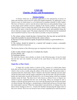
  • 1. UNIT-III Clutches ,Brakes and Dynamometer Friction Clutches A friction clutch has its principal application in the transmission of power of shafts and machines which must be started and stopped frequently. Its application is also found in cases in which power is to be delivered to machines partially or fully loaded. The force of friction is used to start the driven shaft from rest and gradually brings it up to the proper speed without excessive slipping of the friction surfaces. In automobiles, friction clutch is used to connect the engine to the driven shaft. In operating such a clutch, care should be taken so that the friction surfaces engage easily and gradually brings the driven shaft up to proper speed. The proper alignment of the bearing must be maintained and it should be located as close to the clutch as possible. It may be noted that 1. The contact surfaces should develop a frictional force that may pick up and hold the load with reasonably low pressure between the contact surfaces. 2. The heat of friction should be rapidly dissipated and tendency to grab should be at a minimum. 3. The surfaces should be backed by a material stiff enough to ensure a reasonably uniform distribution of pressure. The friction clutches of the following types are important from the subject point of view : 1. Disc or plate clutches (single disc or multiple disc clutch), 2. Cone clutches, and 3. Centrifugal clutches. We shall now discuss, these clutches, in detail, in the following pages. It may be noted that the disc and cone clutches are based on the same theory as the pivot and collar bearings. Single Disc or Plate Clutch: A single disc or plate clutch, as shown in Fig., consists of a clutch plate whose both sides are faced with a friction material (usually of Ferrodo). It is mounted on the hub which is free to move axially along the splines of the driven shaft. The pressure plate is mounted inside the clutch body which is bolted to the flywheel. Both the pressure plate and the flywheel rotate with the engine crankshaft or the driving shaft. The pressure plate pushes the clutch plate towards the flywheel by a set of strong springs which are arranged radially inside the body. The three levers (also known as release levers or fingers) are carried on pivots suspended from the case of the body. These are arranged in such a manner so that the pressure plate moves away from the flywheel by the inward movement of a thrust bearing. The bearing is mounted upon a forked shaft and moves forward when the clutch pedal is pressed. When the clutch pedal is pressed down, its linkage forces the thrust release bearing to move in towards the flywheel and pressing the longer ends of the levers inward. The levers are forced to turn on their suspended pivot and the pressure
  • 2. plate moves away from the flywheel by the knife edges, thereby compressing the clutch springs. This action removes the pressure from the clutch plate and thus moves back from the flywheel and the driven shaft becomes stationary. On the other hand, when the foot is taken off from the clutch pedal, the thrust bearing moves back by the levers. This allows the springs to extend and thus the pressure plate pushes the clutch plate back towards the flywheel. The axial pressure exerted by the spring provides a frictional force in the circumferential direction when the relative motion between the driving and driven members tends to take place. If the torque due to this frictional force exceeds the torque to be transmitted, then no slipping takes place and the power is transmitted from the driving shaft to the driven shaft. Now consider two friction surfaces, maintained in contact by an axial thrust W, as shown in Fig. (a).
  • 3. Let T = Torque transmitted by the clutch, p = Intensity of axial pressure with which the contact surfaces are held together, r1 and r2 = External and internal radii of friction faces, and µ = Coefficient of friction. Consider an elementary ring of radius r and thickness dr as shown in Fig. (b). We know that area of contact surface or friction surface, = 2 π r.dr Normal or axial force on the ring, δW = Pressure × Area = p × 2 π r.dr and the frictional force on the ring acting tangentially at radius r, Fr = µ.δW = µ.p × 2 π r.dr Frictional torque acting on the ring, Tr = Fr × r = µ.p × 2 π r.dr × r = 2 π × µ .p.r2 dr We shall now consider the following two cases : 1. When there is a uniform pressure, and 2. When there is a uniform wear. 1. Considering uniform pressure: When the pressure is uniformly distributed over the entire area of the friction face, then the intensity of pressure, The frictional torque on the elementary ring of radius r and thickness dr is Tr = 2 π µ.p.r2 dr
  • 4. 2. Considering uniform wear: let p be the normal intensity of pressure at a distance r from the axis of the clutch. Since the intensity of pressure varies inversely with the distance, therefore
  • 5. Multiple Disc Clutch: A multiple disc clutch, as shown in Fig, may be used when a large torque is to be transmitted. The inside discs (usually of steel) are fastened to the driven shaft to permit axial motion (except for the last disc). The outside discs (usually of bronze) are held by bolts and are fastened to the housing which is keyed to the driving shaft. The multiple disc clutches are extensively used in motor cars, machine tools etc. Let n1 = Number of discs on the driving shaft, and n2 = Number of discs on the driven shaft. Number of pairs of contact surfaces n = n1 + n2 – 1 and total frictional torque acting on the friction surfaces or on the clutch, T = n.µ.W.R Where R = Mean radius of the friction surfaces
  • 6. Cone Clutch: A cone clutch, as shown in Fig., was extensively used in automobiles but now-a-days it has been replaced completely by the disc clutch. It consists of one pair of friction surface only. In a cone clutch, the driver is keyed to the driving shaft by a sunk key and has an inside conical surface or face which exactly fits into the outside conical surface of the driven. The driven member resting on the feather key in the driven shaft, may be shifted along the shaft by a forked lever provided at B, in order to engage the clutch by bringing the two conical surfaces in contact. Due to the frictional resistance set up at this contact surface, the torque is transmitted from one shaft to another. In some cases, a spring is placed around the driven shaft in contact with the hub of the driven. This spring holds the clutch faces in contact and maintains the pressure between them, and the forked lever is used only for disengagement of the clutch. The contact surfaces of the clutch may be metal to metal contact, but more often the driven member is lined with some material like wood, leather, cork or asbestos etc. The material of the clutch faces (i.e. contact surfaces) depends upon the allowable normal pressure and the coefficient of friction. Consider a pair of friction surface as shown in Fig. (a). Since the area of contact of a pair of friction surface is a frustrum of a cone, therefore the torque transmitted by the cone clutch may be determined in the similar manner as discussed for conical pivot bearings . Let pn = Intensity of pressure with which the conical friction surfaces are held together (i.e. normal pressure between contact surfaces), r1 and r2 = Outer and inner radius of friction surfaces respectively.
  • 7. α = Semi angle of the cone (also called face angle of the cone) or the angle of the friction surface with the axis of the clutch, µ = Coefficient of friction between contact surfaces, and b = Width of the contact surfaces (also known as face width or clutch face). Consider a small ring of radius r and thickness dr, as shown in Fig. (b). Let dl is length of ring of the friction surface, such that dl = dr.cosec α Area of the ring, A = 2π r.dl = 2πr.dr cosec α We shall consider the following two cases : 1. When there is a uniform pressure, and 2. When there is a uniform wear. 1. Considering uniform pressure: We know that normal load acting on the ring,
  • 8. 2. Considering uniform wear: We know that, in case of uniform wear, the intensity of pressure varies inversely with the distance.
  • 9.
  • 10. Centrifugal Clutch: The centrifugal clutches are usually incorporated into the motor pulleys. It consists of a number of shoes on the inside of a rim of the pulley, as shown in Fig. 10.28. The outer surface of the shoes are covered with a friction material. These shoes, which can move radially in guides, are held against the boss (or spider) on the driving shaft by means of springs. The springs exert a radially inward force which is assumed constant. The mass of the shoe, when revolving, causes it to exert a radially outward force (i.e. centrifugal force). The magnitude of this centrifugal force depends upon the speed at which the shoe is revolving. A little consideration will show that when the centrifugal force is less than the spring force, the shoe remains in the same position as when the driving shaft was stationary, but when the centrifugal force is equal to the spring force, the shoe is just floating. When the centrifugal force exceeds the spring force, the shoe moves outward and comes into contact with the driven member and presses against it. The force with which the shoe presses against the driven member is the difference of the centrifugal force and the spring force. The increase of speed causes the shoe to press harder and enables more torque to be transmitted. In order to determine the mass and size of the shoes, the following procedure is adopted : 1. Mass of the shoes: Consider one shoe of a centrifugal clutch as shown in Fig. Let m = Mass of each shoe, n = Number of shoes, r = Distance of centre of gravity of the shoe from the centre of the spider, R = Inside radius of the pulley rim, N = Running speed of the pulley in r.p.m., ω = Angular running speed of the pulley in rad/s = 2πN/60 rad/s, ω1 = Angular speed at which the engagement begins to take place, and µ = Coefficient of friction between the shoe and rim.
  • 11. We know that the centrifugal force acting on each shoe at the running speed, Pc = m.ω2.r and the inward force on each shoe exerted by the spring at the speed at which engagement begins to take place, Ps = m (ω1)2 r The net outward radial force (i.e. centrifugal force) with which the shoe presses against the rim at the running speed = Pc – Ps and the frictional force acting tangentially on each shoe, F = µ (Pc – Ps) Frictional torque acting on each shoe, = F × R = µ (Pc – Ps) R and total frictional torque transmitted, T = µ (Pc – Ps) R × n = n.F.R From this expression, the mass of the shoes (m) may be evaluated. 2. Size of the shoes Let l = Contact length of the shoes, b = Width of the shoes, R = Contact radius of the shoes. It is same as the inside radius of the rim of the pulley. θ = Angle subtended by the shoes at the centre of the spider in radians. p = Intensity of pressure exerted on the shoe. In order to ensure reasonable life, the intensity of pressure may be taken as 0.1 N/mm2 . We know that θ = l/R rad or l = θ.R Area of contact of the shoe, A = l.b and the force with which the shoe presses against the rim = A × p = l.b.p Since the force with which the shoe presses against the rim at the running speed is (Pc – Ps), therefore l.b.p = Pc – Ps From this expression, the width of shoe (b) may be obtained.
  • 12. BRAKES Introduction: A brake is a device by means of which artificial frictional resistance is applied to a moving machine member, in order to retard or stop the motion of a machine. In the process of performing this function, the brake absorbs either kinetic energy of the moving member or potential energy given up by objects being lowered by hoists, elevators etc. The energy absorbed by brakes is dissipated in the form of heat. This heat is dissipated in the surrounding air (or water which is circulated through the passages in the brake drum) so that excessive heating of the brake lining does not take place. The capacity of a brake depends upon the following factors : • The unit pressure between the braking surfaces, • The coefficient of friction between the braking surfaces, • The peripheral velocity of the brake drum, • The projected area of the friction surfaces, and • The ability of the brake to dissipate heat equivalent to the energy being absorbed. The major functional difference between a clutch and a brake is that a clutch is used to keep the driving and driven member moving together, whereas brakes are used to stop a moving member or to control its speed. Materials for Brake Lining: The material used for the brake lining should have the following characteristics: • It should have high coefficient of friction with minimum fading. In other words, the coefficient of friction should remain constant with change in temperature. • It should have low wear rate. • It should have high heat resistance. • It should have high heat dissipation capacity. • It should have adequate mechanical strength. • It should not be affected by moisture and oil. Types of Brakes The brakes, according to the means used for transforming the energy by the braking elements, are classified as : • Hydraulic brakes e.g. pumps or hydrodynamic brake and fluid agitator, • Electric brakes e.g. generators and eddy current brakes, and • Mechanical brakes. The hydraulic and electric brakes cannot bring the member to rest and are mostly used where large amounts of energy are to be transformed while the brake is retarding the
  • 13. load such as in laboratory dynamometers, high way trucks and electric locomotives. These brakes are also used for retarding or controlling the speed of a vehicle for down- hill travel. The mechanical brakes, according to the direction of acting force, may be divided into the following two groups : (a) Radial brakes. In these brakes, the force acting on the brake drum is in radial direction. The radial brakes may be sub-divided into external brakes and internal brakes. According to the shape of the friction elements, these brakes may be block or shoe brakes and band brakes. (b) Axial brakes. In these brakes, the force acting on the brake drum is in axial direction. The axial brakes may be disc brakes and cone brakes. The analysis of these brakes is similar to clutches. Single Block or Shoe Brake: A single block or shoe brake is shown in Fig. 1It consists of a block or shoe which is pressed against the rim of a revolving brake wheel drum. The block is made of a softer material than the rim of the wheel. This type of a brake is commonly used on railway trains and tram cars. The friction between the block and the wheel causes a tangential braking force to act on the wheel, which retard the rotation of the wheel. The block is pressed against the wheel by a force applied to one end of a lever to which the block is rigidly fixed as shown in Fig. The other end of the lever is pivoted on a fixed fulcrum O. Let P = Force applied at the end of the lever, RN= Normal force pressing the brake block on the wheel, r = Radius of the wheel, 2θ= Angle of contact surface of the block, µ = Coefficient of friction, and Ft = Tangential braking force or the frictional force acting at the contact surface of the block and the wheel. If the angle of contact is less than 60°, then it may be assumed that the normal pressure between the block and the wheel is uniform. In such cases, tangential braking force on the wheel, Ft = µ.R N ...(i) and the braking torque, TB = Ft.r = µ.RN.r ... (ii) Let us now consider the following three cases : Case 1. When the line of action of tangential braking force (Ft ) passes through the fulcrum O of the lever, and the brake wheel rotates clockwise as shown in Fig (a), then for equilibrium, taking moments about the fulcrum O, we have
  • 14. Case 2. When the line of action of the tangential braking force (Ft ) passes through a distance ‘a’ below the fulcrum O, and the brake wheel rotates clockwise as shown in Fig. (a), then for equilibrium, taking moments about the fulcrum O,
  • 15. Case 3. When the line of action of the tangential braking force (Ft ) passes through a distance ‘a’ above the fulcrum O, and the brake wheel rotates clockwise as shown in Fig. (a), then for equilibrium, taking moments about the fulcrum O, we have • We see that the moment of frictional force (µ.RN.a) adds to the moment of force (P.l). In other words, the frictional force helps to apply the brake. Such type of brakes are said to be self energizing brakes. When the frictional force is great enough to apply the brake with no external force, then the brake is said to be self- locking brake. From the above expressions, We see that • If x≤ µ.a, then P will be negative or equal to zero. This means no external force is needed to apply the brake and hence the brake is self locking. Therefore the condition for the brake to be self locking is x≤ µ.a • The self locking brake is used only in back-stop applications. • The brake should be self energizing and not the self locking. • In order to avoid self locking and to prevent the brake from grabbing, x is kept greater than µ . a. • If Ab is the projected bearing area of the block or shoe, then the bearing pressure on the shoe, pb = RN / Ab
  • 16. We know that Ab = Width of shoe × Projected length of shoe = w (2rsinθ) • When a single block or shoe brake is applied to a rolling wheel, an additional load is thrown on the shaft bearings due to heavy normal force (RN) and produces bending of the shaft. Pivoted Block or Shoe Brake: We have discussed in the previous article that when the angle of contact is less than 60°, then it may be assumed that the normal pressure between the block and the wheel is uniform. But when the angle of contact is greater than 60°, then the unit pressure normal to the surface of contact is less at the ends than at the centre. In such cases, the block or shoe is pivoted to the lever, as shown in Fig instead of being rigidly attached to the lever. This gives uniform wear of the brake lining in the direction of the applied force. The braking torque for a pivoted block or shoe brake (i.e. when 2 θ> 60°) is given by µ = Actual coefficient of friction. These brakes have more life and may provide a higher braking torque. Double Block or Shoe Brake: When a single block brake is applied to a rolling wheel, an additional load is thrown on the shaft bearings due to the normal force (RN). This produces bending of the shaft. In order to overcome this drawback, a double block or shoe brake, as shown in Fig. is used. It consists of two brake blocks applied at the opposite ends of a diameter of the wheel which eliminate or reduces the unbalanced force on the shaft. The brake is set by a spring which pulls the upper ends of the brake arms together. When a force P is applied to the bell crank lever, the spring is compressed and the brake is released. This type of brake is often used on electric cranes and the force P is produced by an electromagnet or solenoid. When the current is switched off, there is no force on the bell crank lever and the brake is engaged automatically due to the spring force and thus there will be no downward movement of the load. In a double block brake, the braking action is doubled by the use of two blocks and these blocks may be operated practically by the same force which will operate one. In case of double block or shoe brake, the braking torque is given by TB = (Ft1 + Ft2) r Where Ft1 and Ft2 are the braking forces on the two blocks.
  • 17. Simple Band Brake A band brake consists of a flexible band of leather, one or more ropes, or steel lined with friction material, which embraces a part of the circumference of the drum. A band brake, as shown in Fig. is called a simple band brake in which one end of the band is attached to a fixed pin or fulcrum of the lever while the other end is attached to the lever at a distance b from the fulcrum. When a force P is applied to the lever at C, the lever turns about the fulcrum pin O and tightens the band on the drum and hence the brakes are applied. The friction between the band and the drum provides the braking force. The force P on the lever at C may be determined as discussed below: Let T1 = Tension in the tight side of the band, T2 = Tension in the slack side of the band, θ = Angle of lap (or embrace) of the band on the drum, µ = Coefficient of friction between the band and the drum, r = Radius of the drum, t = Thickness of the band, and re = Effective radius of the drum =r+t/2 We know that limiting ratio of the tensions is given by the relation, and braking force on the drum = T1 – T2 ∴Braking torque on the drum, TB = (T1 – T2) r . . . (Neglecting thickness of band) = (T1 – T2) re . . . (Considering thickness of band) Now considering the equilibrium of the lever OBC. It may be noted that when the drum rotates in the clockwise direction, as shown in Fig.(a), the end of the band attached to the fulcrum O will be slack with tension T2 and end of the band attached to B will be tight with tension T1.
  • 18. On the other hand, when the drum rotates in the anticlockwise direction, as shown in Fig.(b) the tensions in the band will reverse, i.e. the end of the band attached to the fulcrum O will be tight with tension T1 and the end of the band attached to B will be slack with tension T2. Now taking moments about the fulcrum O, we have P.l = T1.b . . . (For clockwise rotation of the drum) and P.l = T2.b . . . (For anticlockwise rotation of the drum) Where l = Length of the lever from the fulcrum (OC), and b = Perpendicular distance from O to the line of action of T1 or T2. 1. when the brake band is attached to the lever, as shown in Fig.(a) and (b), then the force (P) must act in the upward direction in order to tighten the band on the drum. 2. If the permissible tensile stress ( ρ ) for the material of the band is known, then maximum tension in the band is given by T1 = ρ w.t Where w = Width of the band, and t = thickness of the band. Differential Band Brake: In a differential band brake, as shown in Fig. the ends of the band are joined at A and B to a lever AOC pivoted on a fixed pin or fulcrum O. It may be noted that for the band to tighten, the length OA must be greater than the length OB.
  • 19. The braking torque on the drum may be obtained in the similar way as discussed in simple band brake. Now considering the equilibrium of the lever AOC. It may be noted that when the drum rotates in the clockwise direction, as shown in Fig (a), the end of the band attached to A will be slack with tension T2 and end of the band attached to B will be tight with tension T1. On the other hand, when the drum rotates in the anticlockwise direction, as shown in Fig. (b), the end of the band attached to A will be tight with tension T1 and end of the band attached to B will be slack with tension T2. Now taking moments about the fulcrum O, we have P.l + T1.b = T2.a ... (For clockwise rotation of the drum) or P.l = T2.a – T1.b ... (i) and P.l + T2.b = T1.a ... (For anticlockwise rotation of the drum) or P.l = T1.a – T2.b ... (ii) We have discussed in block brakes, that when the frictional force helps to apply the brake, it is said to be self energizing brake. In case of differential band brake, we see from equations (i) and (ii) that the moment T1.b and T2.b helps in applying the brake (because it adds to the moment P.l ) for the clockwise and anticlockwise rotation of the drum respectively. We have also discussed that when the force P is negative or zero, then brake is self locking. Thus for differential band brake and for clockwise rotation of the drum, the condition for self locking is T2.a≤T1.b or T2/T1≤b/a and for anticlockwise rotation of the drum, the condition for self locking is T1.a≤T2.b or T1/T2 ≤b/a 1. The condition for self locking may also be written as follows: For clockwise rotation of the drum, T1.b≥T2.a or T1/T2≥a/b and for anticlockwise rotation of the drum, T2.b≥T1.a or T1/T2≥a/b
  • 20. 2. When in Fig. (a) and (b), the length OB is greater than OA, then the force P must act in the upward direction in order to apply the brake. The tensions in the band, i.e. T1 and T2 will remain unchanged. Band and Block Brake: The band brake may be lined with blocks of wood or other material, as shown in Fig. (a). The friction between the blocks and the drum provides braking action. Let there are ‘n’ number of blocks, each subtending an angle 2θ at the centre and the drum rotates in anticlockwise direction. Let T1 = Tension in the tight side, T2 = Tension in the slack side, µ = Coefficient of friction between the blocks and drum, T1′ = Tension in the band between the first and second block, T2′,T3′ etc.= Tensions in the band between the second and third block, between the third and fourth block etc. Consider one of the blocks (say first block) as shown in Fig.(b). This is in equilibrium under the action of the following forces: 1. Tension in the tight side (T1), 2. Tension in the slack side ( T1′ ) or tension in the band between the first and second block, 3. Normal reaction of the drum on the block (RN), and 4. The force of friction ( µ.RN ).
  • 21. Resolving the forces radially, we have --------------- (i) Resolving the forces tangentially, we have --------------- (ii) Dividing equation (ii) by (i), we have Similarly, it can be proved for each of the blocks that ----- (iii) Braking torque on the drum of effective radius re , [Neglecting thickness of band] Internal Expanding Brake: An internal expanding brake consists of two shoes S1 and S2 as shown in Fig. The outer surface of the shoes are lined with some friction material (usually with Ferodo) to increase the coefficient of friction and to prevent wearing away of the metal. Each shoe is
  • 22. pivoted at one end about a fixed fulcrum O1 and O2 and made to contact a cam at the other end. When the cam rotates, the shoes are pushed outwards against the rim of the drum. The friction between the shoes and the drum produces the braking torque and hence reduces the speed of the drum. The shoes are normally held in off position by a spring as shown in Fig. The drum encloses the entire mechanism to keep out dust and moisture. This type of brake is commonly used in motor cars and light trucks. All dimensions in mm
  • 23. Braking of a Vehicle: In a four wheeled moving vehicle, the brakes may be applied to 1. the rear wheels only, 2. the front wheels only, and 3. all the four wheels. In all the above mentioned three types of braking, it is required to determine the retardation of the vehicle when brakes are applied. Since the vehicle retards, therefore it is a problem of dynamics. But it may be reduced to an equivalent problem of statics by including the inertia force in the system of forces actually applied to the vehicle. The inertia force is equal and opposite to the braking force causing retardation. Now, consider a vehicle moving up an inclined plane, as shown in Fig Let α = Angle of inclination of the plane to the horizontal, m = Mass of the vehicle in kg (such that its weight is m.g newtons), h = Height of the C.G. of the vehicle above the road surface in metres, x = Perpendicular distance of C.G. from the rear axle in metres, L = Distance between the centres of the rear and front wheels (also called wheel base) of the vehicle in metres, RA = Total normal reaction between the ground and the front wheels in newtons, RB = Total normal reaction between the ground and the rear wheels in newtons, µ = Coefficient of friction between the tyres and road surface, and a = Retardation of the vehicle in m/s2. 1. When the brakes are applied to the rear wheels only It is a common way of braking the vehicle in which the braking force acts at the rear wheels only. Let FB = Total braking force (in newtons) acting at the rear wheels due to the application of the brakes. Its maximum value is µ.RB. The various forces acting on the vehicle are shown in Fig. For the equilibrium of the vehicle, the forces acting on the vehicle must be in equilibrium. Resolving the forces parallel to the plane,
  • 24.
  • 25.
  • 26.
  • 27. Dynamometer: A dynamometer is a brake but in addition it has a device to measure the frictional resistance. Knowing the frictional resistance, we may obtain the torque transmitted and hence the power of the engine. Types of Dynamometers: Following are the two types of dynamometers, used for measuring the brake power of an engine. 1. Absorption dynamometers, and 2. Transmission dynamometers. In the absorption dynamometers, the entire energy or power produced by the engine is absorbed by the friction resistances of the brake and is transformed into heat, during the process of measurement. But in the transmission dynamometers, the energy is not wasted in friction but is used for doing work. The energy or power produced by the engine is transmitted through the dynamometer to some other machines where the power developed is suitably measured. Classification of Absorption Dynamometers: The following two types of absorption dynamometers are important from the subject point of view : 1. Prony brake dynamometer, and 2. Rope brake dynamometer. These dynamometers are discussed, in detail, in the following pages. Prony Brake Dynamometer: A simplest form of an absorption type dynamometer is a prony brake dynamometer, as shown in Fig.. It consists of two wooden blocks placed around a pulley fixed to the shaft of an engine whose power is required to be measured. The blocks are clamped by means of two bolts and nuts, as shown in Fig.. A helical spring is provided between the nut and the upper block to adjust the pressure on the pulley to control its speed. The upper block has a long lever attached to it and carries a weight W at its outer end. A counter weight is placed at the other end of the lever which balances the brake when unloaded. Two stops S, S are provided to limit the motion of the lever.
  • 28. When the brake is to be put in operation, the long end of the lever is loaded with suitable weights W and the nuts are tightened until the engine shaft runs at a constant speed and the lever is in horizontal position. Under these conditions, the moment due to the weight W must balance the moment of the frictional resistance between the blocks and the pulley. Dynamometers measure the power of the engines . Let W = Weight at the outer end of the lever in newtons, L = Horizontal distance of the weight W from the centre of the pulley in metres, F = Frictional resistance between the blocks and the pulley in newtons, R = Radius of the pulley in metres, and N = Speed of the shaft in r.p.m. We know that the moment of the frictional resistance or torque on the shaft, T = W.L = F.R N-m Work done in one revolution = Torque × Angle turned in radians= T×2πN-m Work done per minute = T×2πNN-m We know that brake power of the engine,
  • 29. Rope Brake Dynamometer: It is another form of absorption type dynamometer which is most commonly used for measuring the brake power of the engine. It consists of one, two or more ropes wound around the flywheel or rim of a pulley fixed rigidly to the shaft of an engine. The upper end of the ropes is attached to a spring balance while the lower end of the ropes is kept in position by applying a dead weight as shown in Fig. In order to prevent the slipping of the rope over the flywheel, wooden blocks are placed at intervals around the circumference of the flywheel. In the operation of the brake, the engine is made to run at a constant speed. The frictional torque, due to the rope, must be equal to the torque being transmitted by the engine. Let W = Dead load in newtons, S = Spring balance reading in newtons, D = Diameter of the wheel in metres, d = diameter of rope in metres, and N = Speed of the engine shaft in r.p.m. Net load on the brake = (W – S) N We know that distance moved in one revolution = π(D+d)m
  • 30. Classification of Transmission Dynamometers: The following types of transmission dynamometers are important from the subject point of view : 1. Epicyclic-train dynamometer, 2. Belt transmission dynamometer, and 3. Torsion dynamometer. Epicyclic-train Dynamometer: An epicyclic-train dynamometer, as shown in Fig. 19.33, consists of a simple epicyclic train of gears, i.e. a spur gear, an annular gear (a gear having internal teeth) and a pinion. The spur gear is keyed to the engine shaft (i.e. driving shaft) and rotates in anticlockwise direction. The annular gear is also keyed to the driving shaft and rotates in clockwise direction. The pinion or the intermediate gear meshes with both the spur and annular gears. The pinion revolves freely on a lever which is pivoted to the common axis of the driving and driven shafts. A weight w is placed at the smaller end of the lever in order to keep it in position. A little consideration will show that if the friction of the pin on which the pinion rotates is neglected, then the tangential effort P exerted by the spur gear on the pinion and the tangential reaction of the annular gear on the pinion are equal. Since these efforts act in the upward direction as shown, therefore total upward force on the lever acting through the axis of the pinion is 2P. This force tends to rotate the lever about its fulcrum and it is balanced by a dead weight W at the end of the lever. The stops S, S are provided to control the movement of the lever.
  • 31. Belt Transmission Dynamometer (Froude or Thorneycroft Transmission Dynamometer): When the belt is transmitting power from one pulley to another, the tangential effort on the driven pulley is equal to the difference between the tensions in the tight and slack sides of the belt. A belt dynamometer is introduced to measure directly the difference between the tensions of the belt, while it is running. A belt transmission dynamometer, as shown in Fig., is called a Froude or Throneycroft transmission dynamometer. It consists of a pulley A (called driving pulley) which is rigidly fixed to the shaft of an engine whose power is required to be measured. There is another pulley B (called driven pulley) mounted on another shaft to which the power from pulley A is transmitted. The pulleys A and B are connected by means of a continuous belt passing round the two loose pulleys C and D which are mounted on a T- shaped frame. The frame is pivoted at E and its movement is controlled by two stops S,S. Since the tension in the tight side of the belt (T1) is greater than the tension in the slack side of the belt (T2), therefore the total force acting on the pulley C (i.e. 2T1) is greater than the total force acting on the pulley D (i.e. 2T2). It is thus obvious that the frame causes movement about E in the anticlockwise direction. In order to balance it, a weight W is applied at a distance L from E on the frame as shown in Fig.. Now taking moments about the pivot E, neglecting friction,
  • 32. Torsion Dynamometer: A torsion dynamometer is used for measuring large powers particularly the power transmitted along the propeller shaft of a turbine or motor vessel. A little consideration will show that when the power is being transmitted, then the driving end of the shaft twists through a small angle relative to the driven end of the shaft. The amount of twist depends upon many factors such as torque acting on the shaft (T), length of the shaft (l), diameter of the shaft (D) and modulus of rigidity (C) of the material of the shaft. We know that the torsion equation is Where θ = Angle of twist in radians, and J = Polar moment of inertia of the shaft. For a solid shaft of diameter D, the polar moment of inertia
  • 33. where k = C.J/l is a constant for a particular shaft. Thus, the torque acting on the shaft is proportional to the angle of twist. This means that if the angle of twist is measured by some means, then the torque and hence the power transmitted may be determined. We know that the power transmitted