1. Clock-Gating and Its Application to Low Power Design of Sequential Circuits
Qing WU
Department of Electrical Engineering-Systems, University of Southern California
Los Angeles, CA 90089, USA, Phone: (213)740-4480
Massoud PEDRAM
Department of Electrical Engineering-Systems, University of Southern California
Los Angeles, CA 90089, USA, Phone: (213)740-4458
Xunwei WU
Department of Electronic Engineering, Hangzhou University
Hangzhou, Zhejiang 310028, CHINA
ABSTRACT
This paper models the clock behavior in a sequential circuit by a quaternary variable and uses this representation
to propose and analyze two clock-gating techniques. It then uses the covering relationship between the triggering
transition of the clock and the active cycles of various flip-flops to generate a derived clock for each flip-flop in
the circuit. Design examples using gated clocks are provided next. Experimental results show that these designs
have ideal logic functionality with lower power dissipation compared to traditional designs.
2. Clock-Gating and Its Application to Low Power Design of Sequential Circuits
I. INTRODUCTION
The sequential circuits in a system are considered major contributors to the power dissipation since one input of
sequential circuits is the clock, which is the only signal that switches all the time. In addition, the clock signal
tends to be highly loaded. To distribute the clock and control the clock skew, one needs to construct a clock
network (often a clock tree) with clock buffers. All of this adds to the capacitance of the clock net. Recent studies
indicate that the clock signals in digital computers consume a large (15% - 45%) percentage of the system power
(1). Thus, the circuit power can be greatly reduced by reducing the clock power dissipation.
Most efforts for clock power reduction have focused on issues such as reduced voltage swings, buffer insertion
and clock routing (2). In many cases switching of the clock causes a lot of unnecessary gate activity. For that
reason, circuits are being developed with controllable clocks. This means that from the master clock other clocks
are derived which, based on certain conditions, can be slowed down or stopped completely with respect to the
master clock. Obviously, this scheme results in power savings due to the following factors:
1) Load on the master clock is reduced and the number of required buffers in the clock tree is decreased.
Therefore, the power dissipation of clock tree can be reduced.
2) The flip-flop receiving the derived clock is not triggered in idle cycles; the corresponding dynamic power
dissipation is thus saved.
3) The excitation function of the flip-flop triggered by derived clock may be simplified since it has a don’t care
condition in the cycle when the flip-flop is not triggered by the derived clock.
In (3) the authors presented a technique for saving power in the clock tree by stopping the clock fed into idle
modules. However, a number of engineering issues related to the design of the clock tree were not addressed and
hence, the proposed approach has not been adopted in practice.
This paper investigates various issues in deriving a gated clock from a master clock. In section II, a quaternary
variable is used to model the clock behavior and to discuss its triggering action on flip-flops. Based on this
analysis, two clock-gating schemes are proposed. In section III, we use the covering relation between the clock
and the transition behaviors of the triggered flip-flops to derive conditions for gating the master clock. Two
common sequential circuits, i.e. 8421 BCD code up-counter and three-excess counter, are then described to
illustrate the procedure for finding a derived clock. In section IV, a new technique for clock-gating is presented
3. which generates a clock synchronous with the master clock. This eliminates the additional skew between the
master clock and the derived clock. Thus, the designed sequential circuit is a synchronous one. Finally, we
present circuit simulation results to prove the quality of the derived clock and its ability to reduce power
dissipation in the circuit.
II. DESCRIPTION FOR CLOCK BEHAVIOR AND CLOCK-GATING
In a synchronous system, a flip-flop is triggered by a certain directional transition of a clock signal. For the clock
to be another signal rather than the master clock, it must offer the same directional transition to trigger the flip-
flop, and it must be “in step” with the master clock.
For the clock signal clk in a circuit if we denote its logic values before and after a transition as clk(t) and clk+
(t)
respectively, four combinations can be used to express different behaviors of the clock as shown in Table 1,
where a special quaternary variable clk
~
denotes the corresponding behavior. The four values are (0, α, β, 1),
where α, β represent two kinds of transition behaviors and 0, 1 represent two kinds of holding behaviors. (Note
that although they have the same forms as signal values 0 and 1, their meanings are different.)
Table 1 QUATERNARY REPRESENTATION FOR BEHAVIORS OF A SIGNAL
~
clk
)()( tclktclk +
→ Behavior
0 0 0 0-holding
α 0 1 α-transition
β 1 0 β-transition
1 1 1 1-holding
In addition, we can also define a literal operation to identify the behavior of a clock:
⎪
⎩
⎪
⎨
⎧
≠
=
,
~
clkif0
=
~
clkif1
b
b
clkb
(1)
where }1,,,0{ βα∈b . Thus, the rising transition clkα
and the falling transition clkβ
of a clock are binary variables
and can serve as arguments of Boolean operations. For example, from Table 1 we have
4. ++++
⋅=⋅=⋅=⋅= clkclkclkclkclkclkclkclkclkclkclkclk 10
and,, βα
.
Assume that there are n flip-flops in a sequential circuit and that their outputs and clock inputs are denoted by Qi
and clki, i = 0,1,«,n-1, respectively. For a synchronous sequential circuit, we have clki = clk, namely all flip-
flops are triggered by the same master clock signal clk. However, if a flip-flop Qi is to be disconnected from the
master clock during some (idle) cycles, then we have to use a derived clock for Qi. Notice that this derived clock
should be “in step” with the master clock for the circuits to remain synchronous.
Generally, we consider that the derived clock is obtained from the master clock clk and the outputs of other flip-
flops 1110 ,,,,, −+− nii QQQQ , (which make transitions following the triggering transition of their respective
clocks.) Since both AND gating and OR gating can be used for controlling the master clock, we have the
following two clock-gating forms
clkpgclk iii ⋅+= , (2)
)( clkpgclk iii +⋅= , (3)
where gi and pi are functions of flip-flop outputs 1110 ,,,,, −+− nii QQQQ .
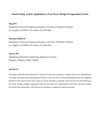
Consider a flip-flop triggered by the falling clock transition as an example (i.e. a negative edge-triggered flip-
flop). The timing relationships of clk, pi, clkpi ⋅ and clkpi + are shown in Fig.1. Note that pi exhibits a delay with
respect to the falling transition of clock, may have glitches (represented by vertical grid lines), and has its final
stable value in the zone where clk = 0. We can see that clkpi + cannot prevent the glitches and may even lead to
an extra glitch. Therefore, only (2) is suitable for the negative edge-triggered flip-flops while (3) is not. Note that
gi in (2) must be glitch-free when clk = 0.
The above discussion shows that the falling transition of clki in (2) occurs for the following two cases:
(1) When gi = 0 and pi = 1, falling transition of clk leads to falling transition of the derived clock clki. Therefore,
pi may be named the transition propagate term.
(2) When gi = 1 and gi makes a falling transition, the derived clock clki makes a falling transition since clk and
hence pi clk⋅ are 0 at that time instance. Therefore, gi may be named the transition generate term.
From this analysis, we obtain
Figure 1 Timing relationship of clk, pi(gi), pi⋅clk and pi+clk
5. .βββ
clkpggclk iiii ⋅⋅+= (4)
Similarly, we can show that the derived clock signal in (3) is suitable for the flip-flops triggered by the rising
transition of the clock. Here gi in (3) must be glitch-free when clk = 1. The rising transition of clki can be
expressed as
clki gi gi pi clkα α α= + ⋅ ⋅ . (5)
It should be pointed out that the attached circuitry needed for generating the derived clock should be simple to
avoid excessive power dissipation due to this overhead circuitry. Therefore gi and pi in (2) and (3) should be
relatively simple functions. Especially, we require gi to be simple to avoid dangerous glitches. Note that if gi = 0,
pi = 1 in (2) or gi = 1, pi = 0 in (3), we return to the condition of applying the master clock clk in a synchronous
sequential circuit.
III. DESIGN OF SEQUENTIAL CIRCUITS BASED ON DERIVED CLOCK
Assume that the derived clock for the flip-flop Qi is clki. Falling transitions of clki have to cover all cycles when
the flip-flop Qi makes transitions, α
iQ and β
iQ . The covering relation can be expressed as:
)( βαβ
iii QQclk +≥ . (6)
Since AND and OR operations on Boolean variables can be interpreted as minimum and maximum operations on
these variables, i.e. ),min( yxyx =⋅ and ),max( yxyx =+ , we can obtain the following equations from (6)
)()( βαβαβ
iiiii QQQQclk +=+⋅ , (7)
.)( ββαβ
iiii clkQQclk =++ (8)
Therefore, we should first obtain ( βα
ii QQ + ) and then generate the derived clock clki for flip-flop Qi . We will
show the procedure by using design examples.
Example 1. Design of an 8421 BCD code up-counter
The next states and state behaviors of an 8421 BCD code up-counter are shown in Table 2, where behavior of
each flip-flop ( +
→ ii QQ ) is denoted by iQ
~
. From Table 2, the corresponding next state Karnaugh maps and
behavior Karnaugh maps may be obtained, as shown in Fig.2(a) and 2(b). In these maps an empty box represents
7. ββα
clkQQQQ ⋅⋅=+ 0311 , (15)
ββα
clkQQ =+ 00 . (16)
From (13)-(15) we find that ≥⋅ β
clkQ0 ( βα
ii QQ + ), (i =1,2,3). From (12), we see that ββ
clkQQ ⋅= 00 can serve as
the needed falling transition trigger for flip-flops Q1, Q2, and Q3, namely ββββ
0321 Qclkclkclk === . Comparing
these with (4), we get 0Qgi = , pi = 0 and 0Qclki = . (i =1,2,3).
As for clk0, (16) indicates that the clock for Q0 is no other than the master clock clk. Since we only need take care
of the excitation input when the flip-flop receives a triggering falling clock transition (i.e. β entries in 0
~
Q map),
we don’t care what the excitation inputs in other conditions are. Therefore the next state Karnaugh maps for flip-
flops Q1, Q2, and Q3 in Fig.2(a) can be simplified to those shown in Fig.2(c).
From Fig.2(a),(c) we can get the corresponding both synchronous and asynchronous designs, as shown in Fig.3.
(We say asynchronous, because now not all flip-flops are triggered at the same time.) Obviously the
corresponding combinational circuits are simpler. Besides, since three flip-flops Q3, Q2, Q1 have no dynamic
power dissipation half of the time when there is no clock triggering, and because the simpler combinational
circuits has lower node capacitance, the asynchronous design is saving power.
Example 2. Design of an excess-three code up-counter
The next state and state transition of an excess-three code up-counter are shown in Table 3. Transition functions
for each flip-flop can be derived as below
βα
clkQQQQ ⋅⋅⋅= 0123 , ββ
clkQQQQ ⋅⋅⋅= 1233 ; (17)
βα
clkQQQQ ⋅⋅⋅= 0122 , ββ
clkQQQQQQQ ⋅⋅⋅+⋅⋅= )( 0121232 ; (18)
βα
clkQQQQQQ ⋅⋅+⋅⋅= )( 010231 , ββ
clkQQQ ⋅⋅= 011 ; (19)
Figure 2
(a) Next state Karnaugh maps, (b) behavior Karnaugh maps, (c) simplified next state Karnaugh maps
Figure 3 Circuit realizations of BCD code up-counter
(a) synchronous design, (b) asynchronous design
9. ββα
])([ 23011 clkQQQQQ ⋅⋅+=+ , (26)
Obviously, if we take clk3 = Q2 , ])([ 2312 clkQQQclk ⋅⋅+= , ])([ 2301 clkQQQclk ⋅⋅+= and clk0 = clk , the covering
relation will set the excitation functions of all the four flip-flops as ii QD = (i =0,1,2,3). On the other hand, if we
use the master clock for triggering all four flip-flops, we obtain the following complicated excitation functions:
230123 QQQQQD ⋅+⋅⋅= ,
03130122 QQQQQQQD ⋅+⋅+⋅⋅= ,
0101231 QQQQQQD ⋅+⋅+⋅= ,
00 QD = .
Since the above D3, D2 and D1 have complicated forms their corresponding synchronous circuit realization will
have a complicated combinational circuit with more node capacitance and hence higher power dissipation. On the
other hand, the corresponding asynchronous circuit realization with ii QD = is much simpler. There is power
saving since the four flip-flops are isolated from the triggering clock in the idle cycles.
IV. SYNCHRONOUS DERIVED CLOCK AND ITS APPLICATION
In the Example 1 of the last section we take ββ
0Qclki = , (i =1,2,3). From (12) we can also write β
iclk as
ββ
clkQclki ⋅= 0 , (i =1,2,3). Comparing this with (4), we have 0=ig , pi = Q0 and clkQclki ⋅= 0 . According to
this form of the derived clock we get another asynchronous design, as shown in Fig.4(a). At the first glance, the
circuit has one AND gate more than the design in Fig.3(b). Besides, it appears that the derived clock clk1-3 may
have an increased phase delay. However, the timing relation shown in Fig.1 indicates that the transition delay of
clk1-3 is independent of the delay of the Q0 output. The delay between clk and clk1-3 is only 2tg (tg is the average
delay of a gate), which is less than the delay of the flip-flop output.
Based on the above discussion, we can rewrite clkQclki ⋅= 0 as clkQclki += 0
*
. Besides, we take clk from the
previous stage of the clock tree. Thus, we obtain a new design, as shown in Fig.4(b). If we consider delay of the
Figure 4. BCD code up-counter by gating clock
(a) asynchronous design, (b) synchronous design
10. inverter and NOR gate being roughly the same, the falling transitions of clk and *
31−clk in the circuit will occur
simultaneously. This design is synchronous in the sense that all flip-flops are triggered in synchrony with the
global clock.
We simulated the new design in Fig.4(b) by SPICE 3f3 using 2μ CMOS technology, which proved that the new
design has an ideal logic operation. We also measure the power dissipation of two synchronous designs in
Fig.3(a) and Fig.4(b). The power dissipation diagrams are shown in Fig.5, and prove that the new design reduces
the power dissipation by 22%.
V. CONCLUSION
The behavioral description of a clock is the basis to analyze its triggering action on flip-flops. Based on it, two
types of clock-gating were introduced to form a derived clock. We showed that the procedure for designing a
derived clock could be systematized so as to isolate the triggered flip-flop from the master clock in its idle cycles.
The achieved power saving can be significant. However, the additional clock skew may lower the maximum
operation frequency. Based on analyzing the timing relation in clock-gating, we then presented a new technique
for generating the derived clock, which is synchronous with the master clock. Circuit simulation proved the
quality of the new derived clock and its capability to reduce power dissipation. The engineering issues
mentioned in (3) have thus been resolved for practical application, opening the path for widespread adoption of
the clock-gating technique in low power design of custom ICs.
Figure 5. Power dissipation diagram
11. REFERENCES
1. M. Pedram, “Power minimization in IC Design: Principles and applications,” ACM Transactions on Design
Automaton, vol. 1, no. 1, pp.3-56, Jan. 1996.
2. G. Friedman, “Clock distribution design in VLSI circuits: an overview,” in Proc. IEEE ISCAS, San Jose,
pp.1475-1478, May 1994.
3. E. Tellez, A. Farrah and M. Sarrafzadeh, “Activity-driven clock design for low power circuits,” in Proc.
IEEE ICCAD, San Jose, pp.62-65, Nov. 1995.