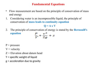
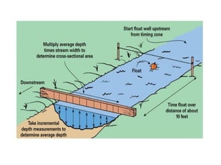
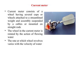
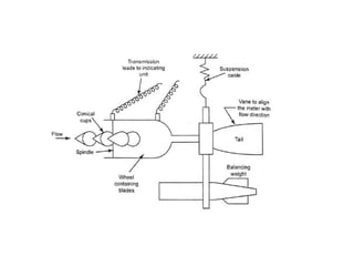
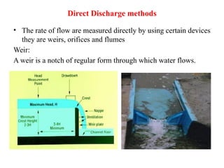
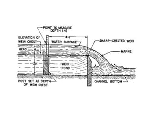
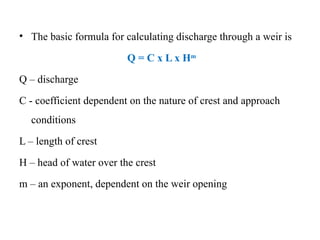
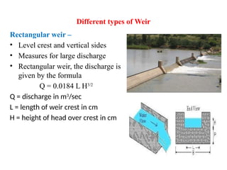
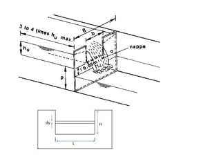
Lecture - 12
Irrigation - measurement of flow in open channels -
velocity area method - Rectangular weir -
Cippoletti weir - V notch - Orifices - Parshall flume
IRRIGATION
• It is the process of artificial application of water to plants at regular interval and it is
help to grow agricultural crops.
Measurement of flow in open channel:
a) Velocity area method
• Float method
• Current meter
• Tracer
b) Direct discharge method
• Weir – Rectangular and Cippoletti weir
• V-notch
• Orifices
• Parshall flume
Measurement of flowing water is usually expressed as litre/second or cubic
metre per second
Fundamental Equations
• Flow measurement are based on the principle of conservation of mass
and energy
1. Considering water is an incompressible liquid, the principle of
conservation of mass leads to continuity equation
Q = A x V
2. The principle of conservation of energy is stated by the Bernouill’s
equation
P = pressure
V = velocity
Z = Elevation about datum head
ϒ = specific weight of liquid
g = acceleration due to gravity
Velocity area method
Float method:
• Cheap and simple and gives only approximate measure of the
rate of flow
• Velocity of flow is made by determining the velocity of an
object floating
• A straight uniform section of the channel about 20 to 25 m long
is selected and marked on the banks
• The time required to traverse the distance by the floating object
is measured and the velocity is calculated
• Mean velocity in the whole of the cross section is obtained by
applying coefficient 0.80 to surface velocity
• Rate of flow = area of cross section x average velocity of flow
Current meter
• Current meter consists of a
wheel having several cups or
wheels attached to a streamlined
weight and assembly suspended
by a cables or mounted on
straight rods
• The wheel in the current meter is
rotated by the action of flowing
water
• The rate at which wheel revolves
varies with the velocity of water
Direct Discharge methods
• The rate of flow are measured directly by using certain devices
they are weirs, orifices and flumes
Weir:
A weir is a notch of regular form through which water flows.
Construction and Placement
of weirs
• The weir should be installed in a
straight line at right angles to the
direction of flow
• The crest and side of the edge should be
sharp edged
• The velocity of approach of water to the
weir should be negligible
• The head over the weir should be
measured on the upstream side at the
distance of at least 4 times the head of
flow from the weir
• The weir crest should be placed no
closer than 2H from the bottom of the
channel
• The distance between end of notch and
sides of the channel should not be less
than 2 times depth of flow of water over
the weir
• The falling water surface from the weir
should have a free flow
• The basic formula for calculating discharge through a weir is
Q = C x L x Hm
Q – discharge
C - coefficient dependent on the nature of crest and approach
conditions
L – length of crest
H – head of water over the crest
m – an exponent, dependent on the weir opening
Different types of Weir
Rectangular weir –
• Level crest and vertical sides
• Measures for large discharge
• Rectangular weir, the discharge is
given by the formula
Q = 0.0184 L H3/2
Q = discharge in m3
/sec
L = length of weir crest in cm
H = height of head over crest in cm
Trapezoidal weir or Cipolleti weir
• Level crest and sides of the notch
sloping outward from the vertical at one
horizontal to four vertical
• The trapezoidal weir with 1:4 side slope
is known as cipolleti weir
• The discharge through Cipoletti weirs
may be computed by the following
formula:
Q = 0.0186 L H3/2
Triangular or V- notch
• The triangular or V- notch weir
is made with different angles
like 450
, 900
and 1200
• The 900
V – Notch is most
commonly used
• More accurate measurements
for lower discharge
• The discharge through 90° V
notch weirs may be computed
by the following formula:
Q = 0.0138 H5/2
Orifices
• An orifice plate can be used to measure water in
comparatively small areas.
• Orifice is an opening with closed perimeter and of a regular
shape through which water flows
• The stream of water coming out of the orifice is known as Jet
• If this jet discharges into the air, the orifice is said to have free
discharges and if the discharge is under water is called a
submerged orifice.
• The depth of water producing the discharge is called head
• Orifice may be circular, square, rectangular or any other
regular shape. Circular and rectangular orifice are most
common for the measurement of water on the farm
• The equation of discharge through a sharp edge orifice is
given by
Q = C.a (2gH)0.5
Q = Discharge in litres per second
a = Area of the orifice opening in sq.cm
G = acceleration due to gravity
H = Head of water causing the flow in cm
C = coefficient (taken as 0.62)
Parshall Flume
• Parshall flume consists of three parts:
• Converging section on upstream end, Constricted section
known as throat and diverging section on the downstream side
• The floor of converging section is level, the floor of throat
inclines downward and the floor of diverging section slopes
upwards
• The size of the parshall flume is specified by its throat width
• To measure the small discharge from a very small fraction of
cu.m per sec. to more than 100cu.m per sec.
THANK YOU

soil and water conservation techniques ppt

  • 1.
    Lecture - 12 Irrigation- measurement of flow in open channels - velocity area method - Rectangular weir - Cippoletti weir - V notch - Orifices - Parshall flume
  • 2.
    IRRIGATION • It isthe process of artificial application of water to plants at regular interval and it is help to grow agricultural crops. Measurement of flow in open channel: a) Velocity area method • Float method • Current meter • Tracer b) Direct discharge method • Weir – Rectangular and Cippoletti weir • V-notch • Orifices • Parshall flume Measurement of flowing water is usually expressed as litre/second or cubic metre per second
  • 3.
    Fundamental Equations • Flowmeasurement are based on the principle of conservation of mass and energy 1. Considering water is an incompressible liquid, the principle of conservation of mass leads to continuity equation Q = A x V 2. The principle of conservation of energy is stated by the Bernouill’s equation P = pressure V = velocity Z = Elevation about datum head ϒ = specific weight of liquid g = acceleration due to gravity
  • 4.
    Velocity area method Floatmethod: • Cheap and simple and gives only approximate measure of the rate of flow • Velocity of flow is made by determining the velocity of an object floating • A straight uniform section of the channel about 20 to 25 m long is selected and marked on the banks • The time required to traverse the distance by the floating object is measured and the velocity is calculated • Mean velocity in the whole of the cross section is obtained by applying coefficient 0.80 to surface velocity • Rate of flow = area of cross section x average velocity of flow
  • 6.
    Current meter • Currentmeter consists of a wheel having several cups or wheels attached to a streamlined weight and assembly suspended by a cables or mounted on straight rods • The wheel in the current meter is rotated by the action of flowing water • The rate at which wheel revolves varies with the velocity of water
  • 8.
    Direct Discharge methods •The rate of flow are measured directly by using certain devices they are weirs, orifices and flumes Weir: A weir is a notch of regular form through which water flows.
  • 9.
    Construction and Placement ofweirs • The weir should be installed in a straight line at right angles to the direction of flow • The crest and side of the edge should be sharp edged • The velocity of approach of water to the weir should be negligible • The head over the weir should be measured on the upstream side at the distance of at least 4 times the head of flow from the weir • The weir crest should be placed no closer than 2H from the bottom of the channel • The distance between end of notch and sides of the channel should not be less than 2 times depth of flow of water over the weir • The falling water surface from the weir should have a free flow
  • 11.
    • The basicformula for calculating discharge through a weir is Q = C x L x Hm Q – discharge C - coefficient dependent on the nature of crest and approach conditions L – length of crest H – head of water over the crest m – an exponent, dependent on the weir opening
  • 12.
    Different types ofWeir Rectangular weir – • Level crest and vertical sides • Measures for large discharge • Rectangular weir, the discharge is given by the formula Q = 0.0184 L H3/2 Q = discharge in m3 /sec L = length of weir crest in cm H = height of head over crest in cm
  • 14.
    Trapezoidal weir orCipolleti weir • Level crest and sides of the notch sloping outward from the vertical at one horizontal to four vertical • The trapezoidal weir with 1:4 side slope is known as cipolleti weir • The discharge through Cipoletti weirs may be computed by the following formula: Q = 0.0186 L H3/2
  • 16.
    Triangular or V-notch • The triangular or V- notch weir is made with different angles like 450 , 900 and 1200 • The 900 V – Notch is most commonly used • More accurate measurements for lower discharge • The discharge through 90° V notch weirs may be computed by the following formula: Q = 0.0138 H5/2
  • 18.
    Orifices • An orificeplate can be used to measure water in comparatively small areas. • Orifice is an opening with closed perimeter and of a regular shape through which water flows • The stream of water coming out of the orifice is known as Jet • If this jet discharges into the air, the orifice is said to have free discharges and if the discharge is under water is called a submerged orifice. • The depth of water producing the discharge is called head • Orifice may be circular, square, rectangular or any other regular shape. Circular and rectangular orifice are most common for the measurement of water on the farm
  • 19.
    • The equationof discharge through a sharp edge orifice is given by Q = C.a (2gH)0.5 Q = Discharge in litres per second a = Area of the orifice opening in sq.cm G = acceleration due to gravity H = Head of water causing the flow in cm C = coefficient (taken as 0.62)
  • 20.
    Parshall Flume • Parshallflume consists of three parts: • Converging section on upstream end, Constricted section known as throat and diverging section on the downstream side • The floor of converging section is level, the floor of throat inclines downward and the floor of diverging section slopes upwards • The size of the parshall flume is specified by its throat width • To measure the small discharge from a very small fraction of cu.m per sec. to more than 100cu.m per sec.
  • 23.