Downloaded 58 times


![C Previous Page
A
Installation 7Maintenance
Contents Zoom In Zoom Out Front Cover Search Issue Next Page EMaGS
B F
725.3(B); 760.3(A); 770.3(A); 800.52(B); You asked specifically about ple- Q: I was reviewing the discussion on the
820.3; 830(A)] only address the “acces- num spaces, but the same text applies BICSI Public Forum about laying cables
sible portion” of an abandoned cable to plenum, riser, and hollow spaces in parallel to each other in a fi xed physical
as “not be permitted to remain.” Arti- the building. If it is “abandoned” and relationship. I noticed that one comment
cle 100 defines “Accessible (as applied to “accessible,” take it out. said that the European norm addresses
wiring methods)” as “Capable of being Seven definitions for almost the same it to some degree. Do you know if any
removed or exposed without damag- term is a lot, even for the NFPA. So, for of the U.S. standards have intentions to
ing the building structure or finish or NEC 2005 the International Brother- address it? I have a client in New Jersey,
not permanently closed in by the struc- hood of Electrical Workers Codes and with a large data center, that is asking
ture or fi nish of the building.” … So, Standards Committee is proposing to me for input. At present they are laying
this is not a surgical removal in a fin- delete the current seven to add a new large bundles of cables into cable trays
ished space. But if the entire area of the definition to Article 100, which would and they want the cables combed as they
building is undergoing demolition for read: “Abandoned Cable. Installed are installed. I told them I would check
remodeling, then all of the cable should cable that is not terminated at both and let them know.
be accessible and removed. ends at equipment and not identified for Bobby Ashton, Jr.,
And then there is Article 645—the future use with a tag.” But so far the RCDD/LAN Specialist
one that did not bother to uniquely other “stakeholders,” who carefully South Windsor, CT
define “abandoned cable,” which is crafted the various definitions in their
only concerned with abandoned cable respective Articles, are not supportive A: Intentions, yes. At the TIA TR-42.1
that is not contained in metal raceway. of this “one-size-fits-all” approach. February 2002 meeting, a presentation
So, metal raceways full of dead cable It is going to be an interesting couple (TR 42.1-2002-013) was made, which ref-
under raised floors in data centers are of years. erenced a list of contributions, previously
not a concern? submitted to either the TR-42.7 Tele-
PANDUIT introduces the affordable and powerful COUGAR ™ LS9
Hand-Held Thermal Transfer Printer
■ Economical identification system provides premium quality solutions at the
lowest installed cost
■ Prints a wide variety of continuous tapes for marking of cables, patch
panels, faceplates and other network applications
■ Legends can be easily aligned with ports on patch panels and faceplates,
eliminating the need for manual spacing and guesswork
■ Cut-to-length functionality eliminates label waste and label trimming labor
■ Partial cut feature available to provide tear-apart strips of labels
■ P1 ™ Label Cassette contains integrated memory device for automatic
formatting, recall of last legend used, and number of labels remaining in
the cassette
■ Fast-loading label cassette includes both label material and ribbon to make
changing labels easy
PANDUIT offers a broad range of economical identification products that aid in
TIA/EIA-606-A compliance including labels, labeling software, and printers.
Visit us at www.panduit.com/p922
Contact Customer Service by email: cs@panduit.com
or by phone: 800-777-3300 and reference ad # p922
Cable Network Partial Cut Strip P1 ™ Label Cassette
Marking Components of Labels
C Previous Page
A
Installation 7Maintenance
Contents Zoom In Zoom Out Front Cover Search Issue Next Page EMaGS
B F](https://image.slidesharecdn.com/cim20070701jul2007-100708124901-phpapp01/85/Cim-20070701-jul_2007-12-320.jpg)

![C Previous Page
A
Installation 7Maintenance
Contents Zoom In Zoom Out Front Cover Search Issue Next Page EMaGS
B F
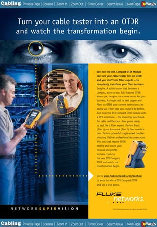
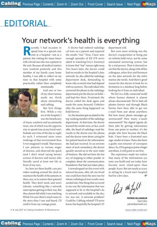
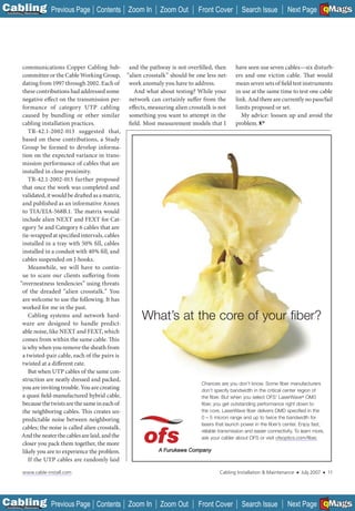
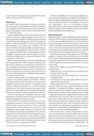
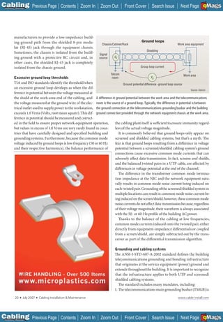
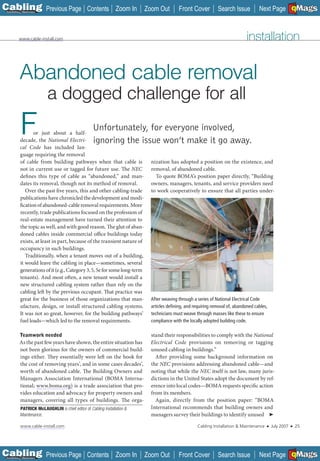
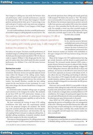
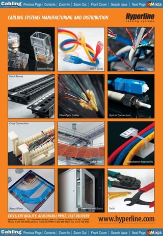
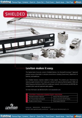
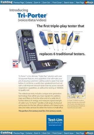
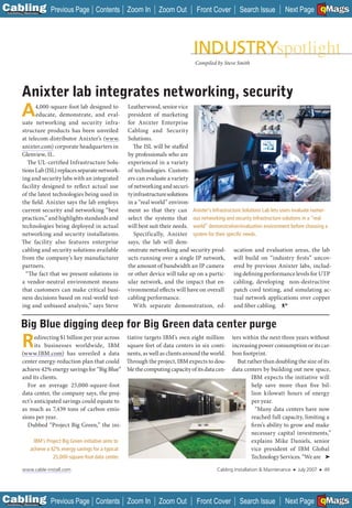
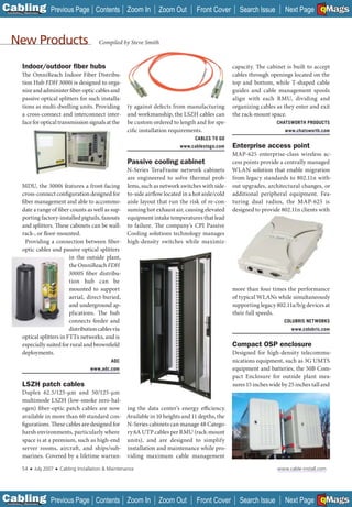
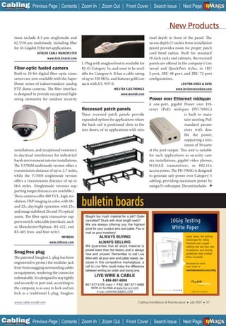
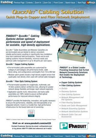
sources, regardless of the presence of an overall screen/shield. Antenna susceptibility:
At frequencies above 30 MHz, noise currents from the envi- UTP vs. ungrounded F/UTP
ronment cannot penetrate the screen/shield due to skin effects, 0
and the internal twisted pairs are fully immune to interfer-
-20
ence. Unfortunately, balance performance is no longer suffi-
cient to ensure adequate noise immunity for UTP cabling at -40
20 db gain
these higher frequencies. This can have an adverse impact on -60
the cabling system’s ability to maintain the SNR levels required
-80
by applications employing DSP technology.
The potential for a cable to behave as an antenna can be -100
experimentally verified by arranging two balanced cables in -120
series, injecting a signal into one cable to emulate a trans- 1 10 100
Frequency (MHz)
mit antenna across a swept frequency range, and measuring
* Data provided courtesy of NEXANS/Berk-Tek
the interference on an adjacent cable to emulate a receiving
antenna. As a rule of thumb, the higher the frequency of the Even when two F/UTP systems are left ungrounded, they still provide
noise source, the greater the potential for interference. The cou- a minimum of 20 dB better performance (blue) than two UTP cables
pling between two UTP cables is a minimum of 40 dB worse (black). [Data provided by Nexans/Berk-Tek.]
than the interaction between two properly grounded F/UTP
cables. It should be noted that 40 dB of margin corresponds to and especially above 30 MHz when cable balance starts to
100 times less voltage coupling, thus confirming the modeled significantly degrade;
predictions. The UTP cable radiates and receives—behaves like • Significantly increased Shannon Capacity for future
an antenna—substantially more than the F/UTP cable. applications.
A second antenna myth is that common mode signals
appearing on a screen or shield can only be dissipated through Fusion of the best
a low-impedance ground path. The fear is that an unground- Achievable SNR margin is dependent upon the combined prop-
ed screen will radiate signals that are “bouncing back and forth” erties of cabling balance and the common mode and differential
and “building up” over the screen/shield. In fact, left unground- mode noise immunity provided by screens and shields. Applica-
ed, a screen/shield will substantially attenuate higher-frequen- tions rely on positive SNR margin to ensure proper signal trans-
cy signals because of the low-pass fi lter formed by its resistance, mission and minimum BER. With the emergence of 10GBase-T,
distributed shunt capacitance, and series inductance. it has become clear that the noise isolation provided by good
The effects of leaving both ends of a foil twisted-pair balance alone is just barely sufficient to support transmission
cable ungrounded can also be verified by using the above- objectives. Furthermore, the alien crosstalk and noise immunity
mentioned experimental method. The coupling between two benefits provided by F/UTP and S/FTP cabling designs
UTP cables is still a minimum of 20 dB worse than the interac- have been demonstrated to offer almost double the Shannon
tion between two ungrounded F/UTP cables. (Note that 20 dB Capacity, a performance advantage that has caught the atten-
of margin corresponds to 10 times less voltage coupling.) Even tion of application developers and system specifiers alike.
under worst-case, ungrounded conditions, the UTP cable It is often said that the telecommunications industry has
behaves more like an antenna than the F/UTP cable. come full circle in the specification of its preferred media type.
Modeled and experimental results clearly dispel these an- In actuality, today’s screened and fully shielded cabling sys-
tenna myth. Screens and shields offer substantially improved tems represent a fusion of best features of the last two gener-
noise immunity compared to unshielded constructions above ations of LAN cabling: excellent balance to protect against
30 MHz, even when improperly grounded. low-frequency interference, and shielding to protect against
The performance benefits of using screened and fully high-frequency interference.
shielded systems include:
• Reduced pair-to-pair crosstalk in fully shielded designs; (Editor’s note: This article is derived from Valerie Rybinski’s
• Reduced alien crosstalk in screened and fully shielded white paper, “Screened and Shielded Cabling: Noise Immuni-
designs; ty, Grounding, and the Antenna Myth.” The paper contains in-
• Screened Category 6A cable diameters that are smaller formation used in this article, as well as a full explanation of
than many 6A UTP cables, allowing greater pathway fi ll/ the simplified loop antenna model, a complete bibliography of
utilization; Rybinski’s sources, and a glossary of terms and acronyms. The
• Substantially improved noise immunity at all frequencies, white paper is available at www.siemon.com.)
www.cable-install.com Cabling Installation & Maintenance ■ July 2007 ■ 23
C Previous Page
A
Installation 7Maintenance
Contents Zoom In Zoom Out Front Cover Search Issue Next Page EMaGS
B F](https://image.slidesharecdn.com/cim20070701jul2007-100708124901-phpapp01/85/Cim-20070701-jul_2007-25-320.jpg)
![C Previous Page
A
Installation 7Maintenance
Contents Zoom In Zoom Out Front Cover Search Issue B
Next Page EMaGS F
cable. If such wires exist, members should identify the wiring the local authority having jurisdiction.Though this author did
by its rating (riser rated “CMR,” plenum rated “CMP”) and its not get an on-the-record comment concerning enforcement
use (communications, alarm, security, etc.). The NEC 2002 and of abandoned-cable removal, some commented anonymously
2005 include language that allows some cabling to be retained that enforcement varies from jurisdiction to jurisdiction.
if it is tagged for future use as long as it meets the permitted
use criteria specified for cable installations (i.e., minimum of Words getting in the way?
“CMR” and/or “CMP”). Any cable that does not meet the per- One potential reason for such unpredictable enforcement could
mitted use specifications should be removed. be the sometimes-confounding wording within the NEC in
which abandoned cable is referenced. The 2002 NEC includes
Leasing language seven separate sections that mandate the cable’s removal, and
The BOMA paper continues: “Your leases should clearly state an accompanying seven individual sections that define the
that tenants must remove any cabling that is abandoned dur- term “abandoned cable.”
ing the term of their tenancy, and/or your license agreements The seven sections of NEC 2002 that contain the definitions
should require service providers to remove all wires upon the are: 640.2, 725.2, 760.2, 770.2, 800.2, 820.2, and 830.2. The
termination of the contract. We recommend that you review seven sections with the removal language are: 640.3, 725.3,
your leases and license agreements to ascertain exactly who 760.3, 770.3, 800.52, 820.3, and 830. The requirements for
was responsible for the installation and/or abandoning of the removal are worded essentially the same, as follows: “The ac-
cabling and whether you have recourse to recover any of the cessible portion of abandoned [application for which cables are
funds needed to remove the wire. Next, make any amend- used, or cable type] cables shall not be permitted to remain.”
ments necessary if you are not already protected by these Simply, the code-based requirements to remove abandoned
agreements.” cables are not going away. How quickly those abandoned
As BOMA pointed out to its membership, abandoned cable cables themselves are going away appears to depend on the
is a code issue within those jurisdictions that have adopted tenacity of building owners/managers, along with the enforce-
the 2002 or 2005 NEC. As such, it is subject to enforcement by ment procedures of the local AHJ.
____________
C Previous Page
A
Installation 7Maintenance
Contents Zoom In Zoom Out Front Cover Search Issue B
Next Page EMaGS F](https://image.slidesharecdn.com/cim20070701jul2007-100708124901-phpapp01/85/Cim-20070701-jul_2007-28-320.jpg)

![C Previous Page
A
Installation 7Maintenance
Contents Zoom In Zoom Out Front Cover Search Issue B
Next Page EMaGS F
are related to crosstalk between wire pairs in the cable and other cabling installation issues. IEEE 802.3an development
signal reflection on each wire pair measured by the return has been completed and was approved by it standards board
loss parameter. in June 2006.
Because of the very high frequency range required for The cabling industry is undertaking two sets of activities:
10GBase-T, the crosstalk requirements must be expanded to • Guidelines for cabling compliance with the transmission
include not only the crosstalk that happens between wire pairs requirements of 10GBase-T;
within each cabling link, but also to include the crosstalk that • A new cabling standard that delivers better transmission
is induced from wire pairs in adjacent cabling links. The lat- performance than Category 6, called Augmented Catego-
ter is called alien crosstalk. The performance of each individ- ry 6 (Category 6A) or Augmented Class E (abbreviated
ual cabling link is certified by the “in-channel” tests, while Class EA by the International Organization for Standard-
the alien crosstalk performance or the coupling between wire ization [ISO]).
pairs in adjacent links is to be certified by the “between-chan- In the North American market, the Telecommunications
Industry Association (TIA; www.tiaonline.org) is the lead-
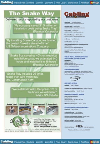
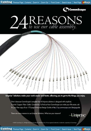
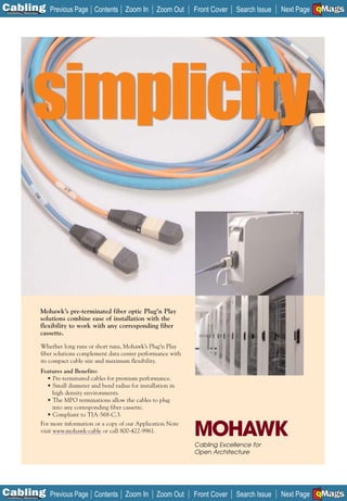
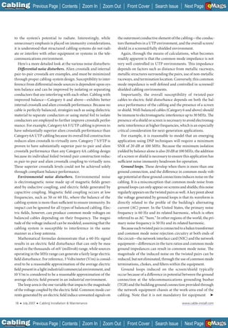
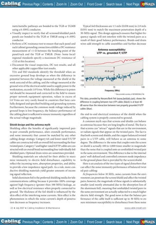
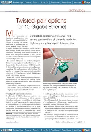
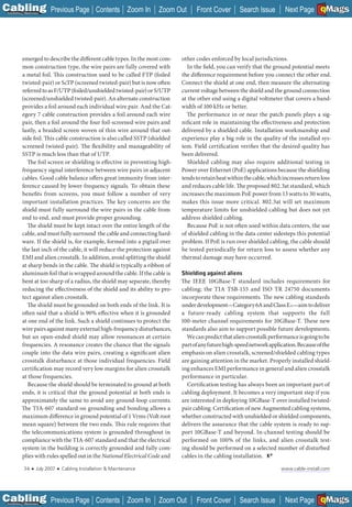
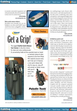
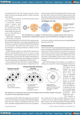
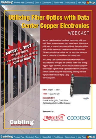
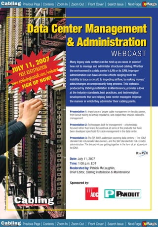
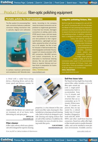
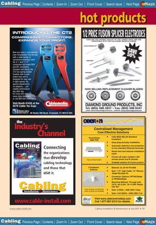
UTP vs. screened UTP cable construction
ing standards body for data communications cabling. The ISO,
UTP STP meanwhile, develops, publishes, and maintains standards for
Conductor Conductor the worldwide market. Both standards bodies are involved
Insulation Insulation with the two activities mentioned above.
Pair Pair
Sheath Pair shield
Cabling guidelines for compliance with 10GBase-T
Sheath
The TIA published a document titled Telecommunications
Systems Bulletin 155 (TIA TSB-155), which contains the
S/UTP S/STP guidelines and performance criteria by which any cabling
Conductor Conductor
system can be evaluated for compliance with the cabling
Insulation Insulation transmission requirements for 10GBase-T. The guidelines
Pair Pair in TSB-155 address the in-channel performance (test
Shield Pair shield parameters that define the performance of an individual
Sheath Cable shield cabling link over the frequency range from 1 through
Sheath 500 MHz) and the between-channel performance
Source: Fluke Networks (signal coupling between adjacent links commonly referred
Adding a foil shield around the four pairs of Unshielded Twisted Pair to as alien crosstalk). The ISO is in the process of creating a
(UTP) creates Screened UTP (S/UTP). Wrapping a foil shield around Technical Report (TR 24750) that serves the same purpose,
each pair creates Shielded Twisted Pair (STP). Screened STP (S/STP) and intends to provide the same guidance as the TIA
adds a foil screen around all four shielded wire-pairs. TSB-155 document. (These guidelines do not suppose a
specific Category or Class of cabling, but it will be
nel” test parameters. difficult to meet the performance established by TSB-155
How can you be assured that the installed cabling system [TR 24750] for any cabling lower than Category 6 or Class E.)
will support 10GBase-T transmission? Industry standards
define the test parameters as well as the measurement method- New cabling standards
ology to assure compliance of installed cabling systems. This Both TIA and ISO are developing a new cabling type called
testing procedure is called cabling certification. Augmented Category 6 (Category 6A) or Augmented Class
E (Class EA). This new cabling will offer better performance
Applying the standards than Category 6 or Class E cabling. The performance of the
The IEEE has been the organization to develop, expand, and in-channel and between-channel parameters will be defined
maintain the “Ethernet” standards, in its 802.3 set of spec- up to 500 MHz. The standards activities that defi ne the Aug-
ifications. IEEE project 802.3an developed and defined the mented cabling systems are not yet complete, even though
system to transmit 10-GbE over twisted-pair cabling. This many manufacturers offer Category 6A (Class EA) solutions
project encompasses all aspects of the network implementation, in the market. The TIA development is further along than the
including the minimum capability of the cabling link between ISO development, and will be published as Addendum 10 to
a transmitting device and a receiving device. The IEEE is the TIA standard 568-B.2 (TIA-568-B.2-10). This TIA docu-
focused on the transmission performance of the end-to-end ment is, at the time of this writing, in Draft 7.0.
cabling link independent of the number of connections or An important reason for the new cabling systems is ➤
30 ■ July 2007 ■ Cabling Installation & Maintenance www.cable-install.com
C Previous Page
A
Installation 7Maintenance
Contents Zoom In Zoom Out Front Cover Search Issue B
Next Page EMaGS F](https://image.slidesharecdn.com/cim20070701jul2007-100708124901-phpapp01/85/Cim-20070701-jul_2007-32-320.jpg)
![C Previous Page
A
Installation 7Maintenance
Contents Zoom In Zoom Out Front Cover Search Issue B
Next Page EMaGS
F
P R E - T E R M I N AT E D ,
PRE-TESTED,
PRE-ANYONE ELSE.
PROVEN PERFORMANCE. PROVEN RELIABILITY. RAPIDNET. When it comes to pre-terminated network cabling
solutions, HellermannTyton is the leader. Pioneering the first Category 6 pre-terminated network cabling system,
HellermannTyton has, for years, delivered successful RapidNet installations across the globe – including leading US
data centers in government, financial, healthcare, educational and enterprise applications. RapidNet is available
in copper and fiber modular configurations and offers the time tested performance and reliability required
for system critical applications. Assuring on-time project completion in the most demanding circumstances,
RapidNet has been verified to reduce installation time by 85% over traditional methods.
RapidNet has been proven in the field, now let us prove to you how RapidNet can enhance your business. Go
online for more information and register for your free “Proven in the Field” t-shirt, www.hellermann.tyton.com/cm1
phone: [80 0] 822 4352
email: info@htamericas.com
w w w. h e l l e r m a n n .t y t o n . c o m /c m1
____________________
C Previous Page
A
Installation 7Maintenance
Contents Zoom In Zoom Out Front Cover Search Issue B
Next Page EMaGS
F](https://image.slidesharecdn.com/cim20070701jul2007-100708124901-phpapp01/85/Cim-20070701-jul_2007-38-320.jpg)
![C Previous Page
A
Installation 7Maintenance
Contents Zoom In Zoom Out Front Cover Search Issue Next Page EMaGS
B F
Big Green initiative that can reduce cabling costs; ing system.
continued from page 49 • Virtualize IT infrastructures, such as “Relief from the energy crisis can’t be
providing clients the IBM action plan to emerging hybrid systems that feature achieved through incremental improve-
make their data centers fully utilized and special purpose processors designed ments,” says Bill Zeitler, senior vice pres-
energy efficient.” to improve performance and reduce ident of IBM System and Technology
Specifically, Project Big Green will in- energy consumption; Group. “Bold ideas and actionable plans
volve a five-step approach to data center
energy savings: “Relief from the energy crisis can’t be achieved
• Evaluate existing facilities with en-
ergy assessment, virtual 3-D power through incremental improvements.”
management, and thermal analytics—
including identifying and resolving • Seize control with power manage- are needed to deal with this issue.”
existing/potential heat-related issues ment soft ware, such as provision- Project Big Green includes a new glob-
that could create outages; ing soft ware that can reduce 80% of al “green team” of more than 850 energy-
• Plan, build or update to an ener- power consumption on servers by efficiency architects from across IBM.
gy-efficient data center, includ- putting them on standby mode when The company also plans to launch a
ing a free online self-assessment of not needed; Web-enabled clearinghouse, the Ener-
data center energy use, the op- • Exploit liquid cooling solutions gy Efficiency Incentive Finder, which
tion of a pre-configured 500 or both inside and outside of the data will include details about incentives
1,000-square-foot data center with center, including IBM’s patented and programs that are available from
energy-efficient technology, and “stored cooling” technology designed local utility companies, governments,
a solution for improving air flow to significantly increase the efficiency and other participating agencies around
under the data center raised floor of the data center’s end-to-end cool- the world.
Short runs…
DURHAM, NH—The University of New Hampshire Interoperability RICHARDSON, TX—A Web-based printing program for producing
Lab (UNH IOL; (www.iol.unh.edu) recently conducted multi-vendor telecommunications system labels has been unveiled by
10GBase-T interoperability for Fulcrum Microsystems, Solarflare CommScope (www.commscope.com) that enables SYSTIMAX
Communications, and Teranetics. Solarflare and Teranetics BusinessPartners to create professional product labels for
demonstrated their independent 10GBase-T PHY implementation specific installations. The customized solution replaces the static
using different systems at either end of the link. Tests were repeated templates available on the company’s website, and provides
multiple times over a 55-meter, two-connector topology of Category two ways to create labels. The software supports labeling on a
6 cabling to show support for legacy installed cabling. A network number of SYSTIMAX products, including M2000/M3000 panels,
throughput and latency benchmark showed that the link sustained PATCHMAX PS panels, LE and L faceplates, and VisiPatch/
a throughout of 10-Gbits/sec. The tests used two different switch VisiPatch 360 panels.
designs from Fulcrum Microsystems (www.fulcrummicro.com).
______________
SACRAMENTO, CA—Low-power semiconductor transceiver
Mike Zeile, vice president of marketing at Fulcrum, says, “These
developer KeyEye Communications (www.keyeye.net) and copper
two switch reference designs will provide OEM customers with
transceiver manufacturer Methode Electronics (www.methode.com)
quick-to-market [Ethernet] platforms that have the assurance of
will jointly develop 10-Gigabit Ethernet copper MSA pluggable
interoperability.”
modules compatible with the short-reach, lower-power mode of
SALT LAKE CITY, UT—Silex Technologies (www.silexamerica. the IEEE 802.3an 10GBase-T standard. The companies say the
com) has unveiled Multicast Video Distribution System (MVDS), a
__ modules will help data center managers significantly reduce cost
wired/wireless video distribution system designed for the digital and power consumption resulting from a growing array of
sign industry. MVDS’ digital multicast technology and an advanced 10-Gigabit servers and switches.
compression algorithm lets it support large numbers of displays
WATERTOWN, CT—Siemon’s (www.siemon.com) EMEA (Europe,
at long distances with no image degradation. Designed for airport
Middle East and Africa) manufacturing operations and logistics
arrival/departure areas, trade shows, retail advertising, classrooms,
center’s Quality Management System in Brno, Czech Republic,
and emergency information displays, the MVDS technology can
has been certified ISO9001:2000. The Brno facility will serve as
connect using industry-standard Ethernet cabling and hardware, or
Siemon’s pan-EMEA logistics hub, housing stock and acting as the
via 802.11a wireless networking. Silex says its technology eliminates
key distribution center for the company’s markets. In addition, the
the need to use more expensive analog splitters and repeaters.
facility houses IT cabling component manufacturing operations.
52 ■ July 2007 ■ Cabling Installation & Maintenance www.cable-install.com
C Previous Page
A
Installation 7Maintenance
Contents Zoom In Zoom Out Front Cover Search Issue Next Page EMaGS
B F](https://image.slidesharecdn.com/cim20070701jul2007-100708124901-phpapp01/85/Cim-20070701-jul_2007-54-320.jpg)

The document discusses Corning UniCam Pretium fiber optic connectors that provide exceptional optical performance without epoxy or polishing due to their laser-cleaved and factory-polished fiber stub. It also discusses how the Corning cable systems focus on customer-focused innovation and how their connectors enable less than 1 dB of insertion loss. The second document discusses how the Fluke DTX Compact OTDR module can transform a cable tester into an OTDR, allowing technicians to perform fiber certification and troubleshooting. It notes how this could help businesses perform new fiber jobs and increase their revenue. The third document discusses how Optical Cable Corporation has a network of distributors across the US to provide fiber optic cables to


![Pos didatica aula 1 unidade i presencial[1]](https://cdn.slidesharecdn.com/ss_thumbnails/posdidaticaaula1unidadeipresencial1-100622074059-phpapp01-thumbnail.jpg?width=640&height=640&fit=bounds)


![Estresse[1]](https://cdn.slidesharecdn.com/ss_thumbnails/estresse1-100504162030-phpapp01-thumbnail.jpg?width=640&height=640&fit=bounds)


