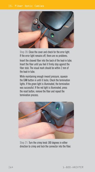
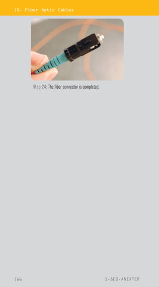
This document is an installation pocket reference guide from Anixter, a leading global distributor of enterprise cabling, security solutions, electrical and electronic products. The guide provides information on cabling standards, building subsystems, types of cables (twisted pair, coaxial, fiber optic), cable preparation and termination procedures. It aims to help users understand cabling systems and properly install cabling infrastructure.


![|2. Building Subsystems
|12 1.800.ANIXTER
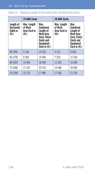
SECTION 2: BUILDING SUBSYSTEMS
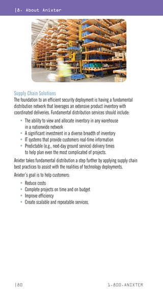
The Six Subsystems of a Structured Cabling System
Note: This portion of the reference guide is based on two standards titled
ANSI/TIA-568-C.0 (Generic Telecommunications Cabling for Customer Premises),
which is used for generic infrastructures, and ANSI/TIA-568-C.1 (Commercial
Building Telecommunications Cabling Standard [see p. 6]), which is more
commonly used with typical commercial building infrastructures. These two
standards are fully consistent with each other regarding the telecommunications
infrastructure topology. However, they occasionally use different terms for the
same system components. In this reference guide when different terms exist
between the two standards for the same component, the more common 568-C.1
version will be used first, followed by the 568-C.0 (generic version) in square
parentheses. Example: work area (WA) [equipment outlet (EO)].
1
2
3
4
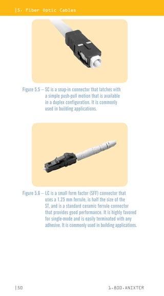
5
6
6
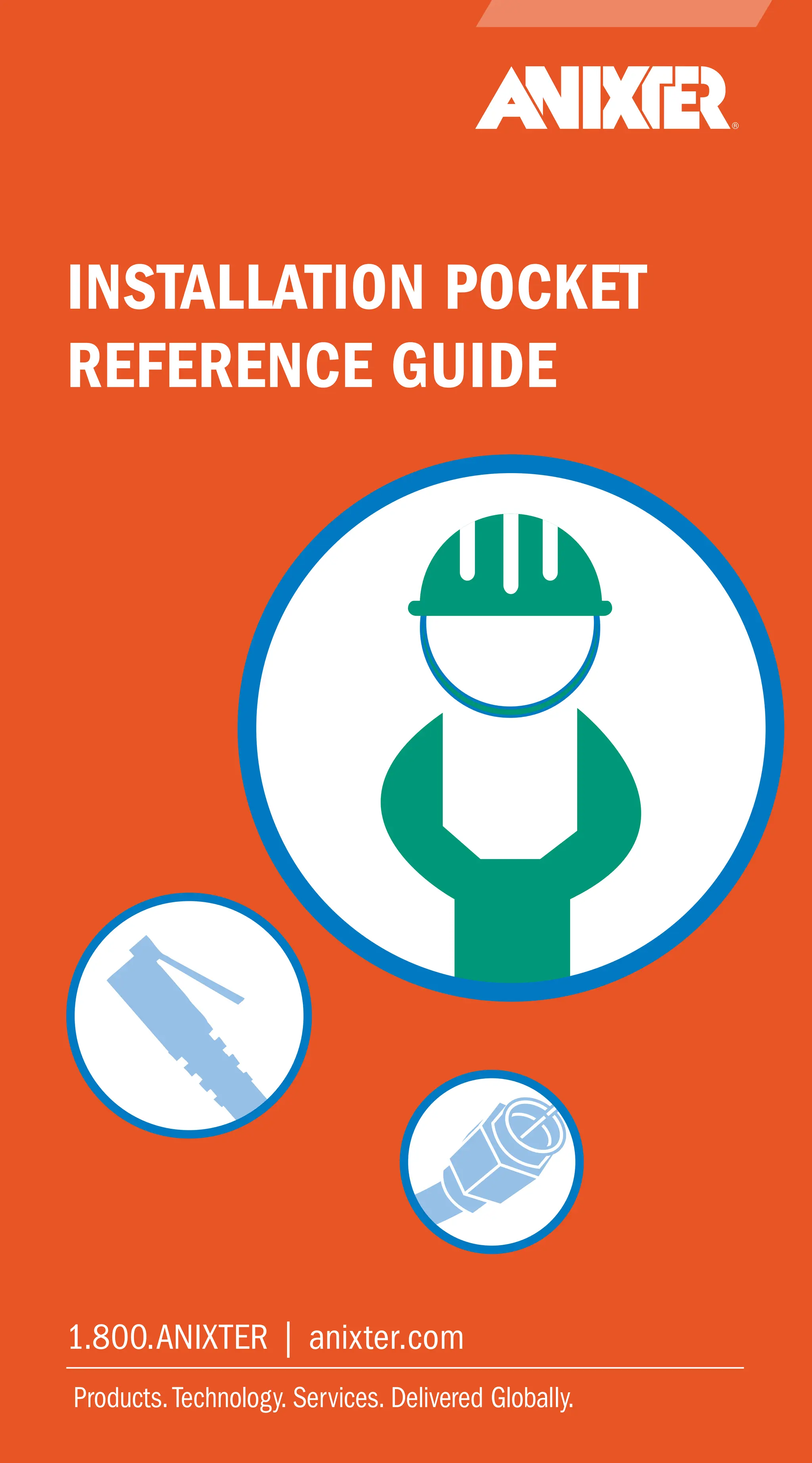
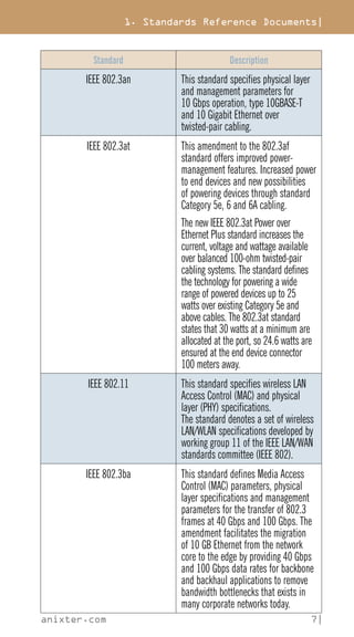
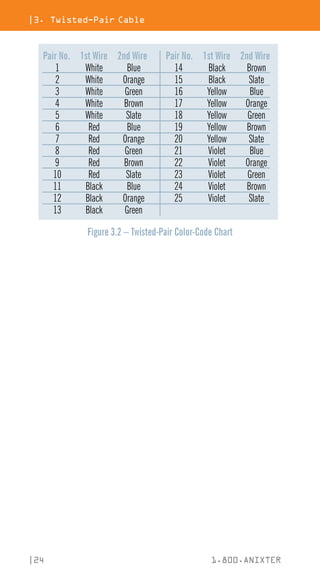
Figure 2.1 – Six Subsystems of a Structured Cabling System
Subsystems Key
1 Entrance Facilities
2 Equipment Room
3 Backbone Cabling
4 Telecommunications
Room and Enclosure
5 Horizontal Cabling
6 Work Area](https://image.slidesharecdn.com/12h0005x00-anixter-installation-pocket-reference-guide-book-wc-en-us-231025020354-6403acba/85/12H0005X00-Anixter-Installation-Pocket-Reference-Guide-BOOK-W-C-EN-US-pdf-15-320.jpg)
![2. Building Subsystems|
anixter.com 13|
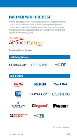
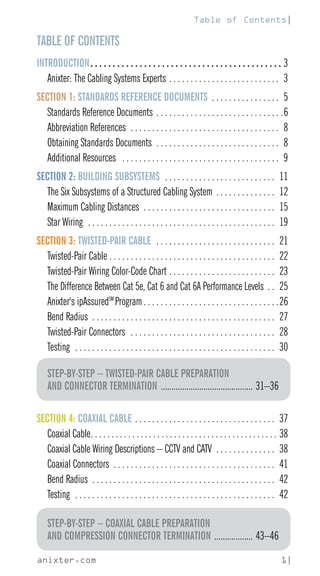
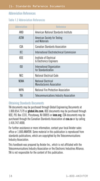
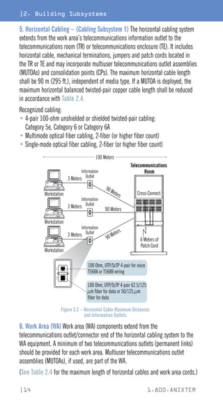
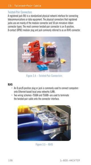
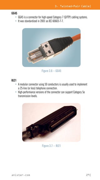
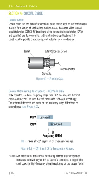
1. Entrance Facilities (EF) Entrance facilities contain the cables, network
demarcation point(s), connecting hardware, protection devices and other
equipment that connect to the access provider (AP) or private network cabling.
It includes connections between outside plant and inside building cabling.
2. Equipment Room (ER) The environmentally controlled centralized space
for telecommunications equipment is usually more complex than a
telecommunications room (TR) or telecommunications enclosure (TE). It usually
houses the main cross-connect (MC) [Distributor C] and may also contain the
intermediate cross-connects (ICs) [Distributor B], horizontal cross-connects
(HCs) [Distributor A], or both.
3. Backbone Cabling The backbone cabling provides interconnection between
telecommunications rooms, equipment rooms, access provider (AP) spaces and
entrance facilities. There are two subsystems defined for backbone cabling:
•
Cabling Subsystem 2 – Backbone cabling between the horizontal
cross-connect (HC) [Distributor A (DA)] and the intermediate cross-connect
(IC) [Distributor B (DB)]
•
Cabling Subsystem 3 – Backbone cabling between an intermediate
cross-connect (IC) [Distributor B (DB)] and the main cross-connect (MC)
[Distributor C (DC)]
Recognized cabling:
• 100-ohm twisted-pair cabling: Category 3, Category 5e, Category 6 or Category 6A
•
Multimode optical fiber cabling: 850 nm laser-optimized 50/125 μm
is recommended; 62.5/125 μm and 50/125 μm is allowed
• Single-mode optical fiber cabling
(See Tables 2.2 and 2.3 on the following pages for maximum supportable
distances for copper and fiber backbones.)
4. Telecommunications Room (TR) and Telecommunications Enclosure (TE)
A TR or TE houses the terminations of horizontal and backbone cables to
connecting hardware including any jumpers or patch cords. It may also contain
the IC or MC for different portions of the backbone cabling system. The TR or TE
also provides a controlled environment to house telecommunications equipment,
connecting hardware and splice closures serving a portion of the building.
The use of a telecommunications enclosure (TE) is for a specific implementation
and not a general case. It is intended to serve a smaller floor area than a TR and
may be used in addition to the minimum one TR per floor rule.](https://image.slidesharecdn.com/12h0005x00-anixter-installation-pocket-reference-guide-book-wc-en-us-231025020354-6403acba/85/12H0005X00-Anixter-Installation-Pocket-Reference-Guide-BOOK-W-C-EN-US-pdf-16-320.jpg)
![2. Building Subsystems|
anixter.com 19|
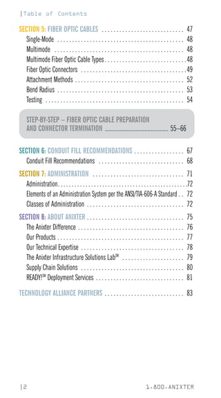
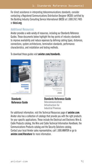
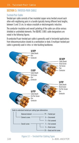
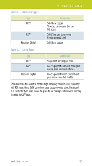
Star Wiring
Cabling shall be installed in a hierarchal star topology. There shall be no more
than two cross-connects [Distributors] between the main cross-connect (MC)
[Distributor C] and the work area (WA) [equipment outlet – EO].
Telecommunications Rooms
Figure 2.3 – Star Topology Diagram
Equipment Room
Main Cross-Connect
Inter-
building
Equipment Room
Intermediate
Cross-Connect
Backbone Distances*
Inter-
building
*Note:
Please refer to Tables 2.2 and 2.3 (on previous pages) for maximum
distances based on media type and application.](https://image.slidesharecdn.com/12h0005x00-anixter-installation-pocket-reference-guide-book-wc-en-us-231025020354-6403acba/85/12H0005X00-Anixter-Installation-Pocket-Reference-Guide-BOOK-W-C-EN-US-pdf-22-320.jpg)


![6. Conduit Fill Recommendations|
anixter.com 69|
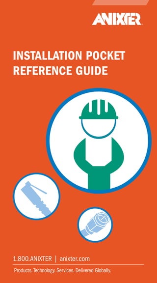
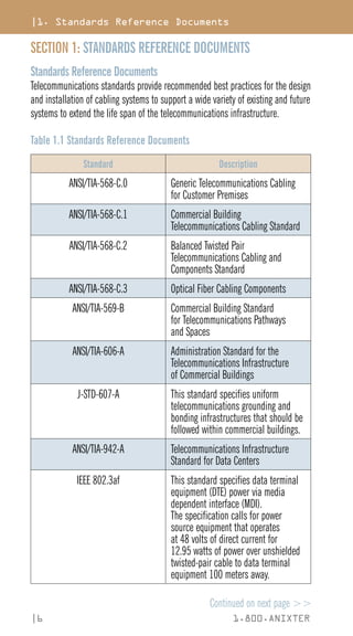
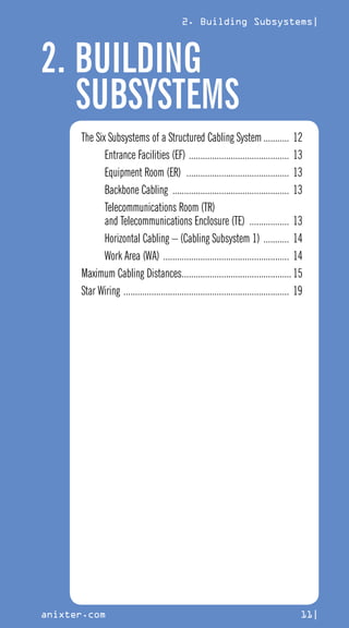
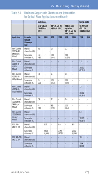
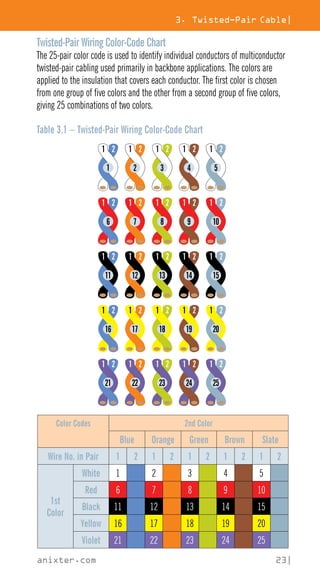
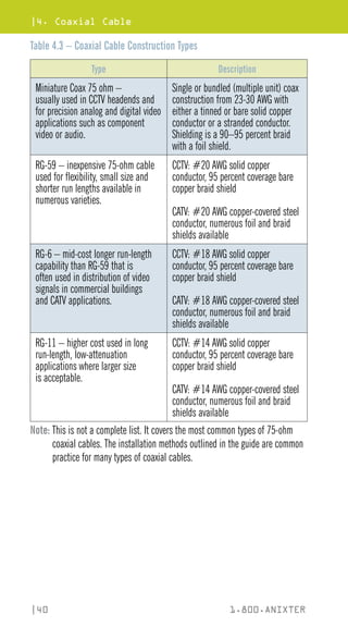
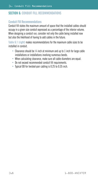
Examples of conduit fill based on sample sizing of cables are listed below.
Table 6.1 – Conduit Fill Recommendations
Sample Cable Outside Diameters (mm [in.])
Conduit Inside
Diameter
mm (in.)
Trade
Size
4.5
(0.15)
5
(0.19)
6
(0.23)
7
(0.27)
8
(0.31)
9
(0.35)
21 (0.82) 3/4 11 7 5 3 3 2
27 (1.04) 1 18 11 8 6 4 3
35 (1.38) 1-1/4 30 19 13 10 8 6
41 (1.61) 1-1/2 41 26 18 13 10 8
50 (2.06) 2 68 43 30 22 17 13
63 (2.46) 2-1/2 96 62 43 31 24 19
75 (3.06) 3 149 95 66 49 37 29
91 (3.54) 3-1/2 199 127 88 65 50 39
100 (4.02) 4 255 163 113 83 64 50
Note: The calculations used in Table 6.1 to determine cable fill are based on
a 40 percent initial fill factor assuming straight runs with no degrees of bend.
These conduit sizes are typical in the United States and Canada and may vary in
other countries. The metric trade designators and imperial trade sizes are not
literal conversions of metric to imperial sizes. Fire and smoke stop assemblies
may require different fill ratios.
Reference: BICSI 2008 Telecommunications Distribution Methods Manual.](https://image.slidesharecdn.com/12h0005x00-anixter-installation-pocket-reference-guide-book-wc-en-us-231025020354-6403acba/85/12H0005X00-Anixter-Installation-Pocket-Reference-Guide-BOOK-W-C-EN-US-pdf-72-320.jpg)