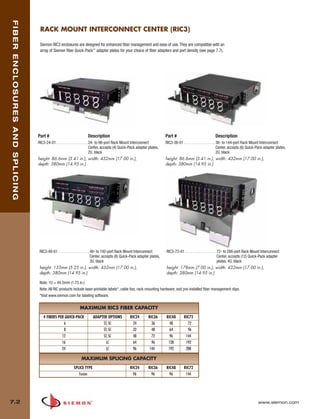
Downloaded 17 times
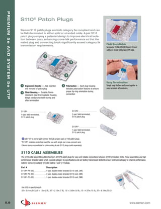
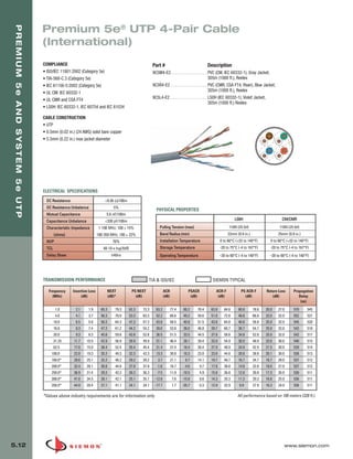
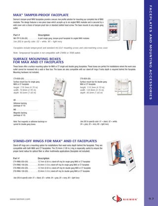
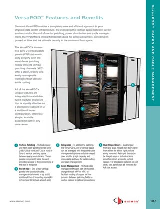
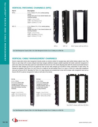
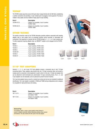
![01_TERA_2010.qxd:ZMax_Catalog 1/4/10 11:07 AM Page 8
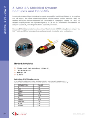
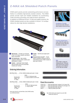
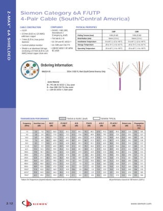
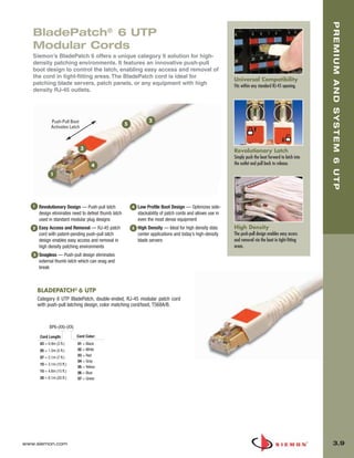
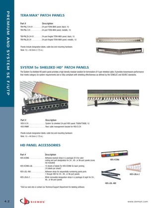
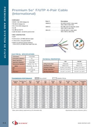
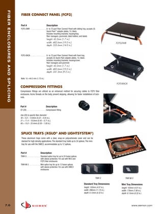
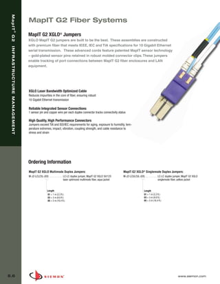
C AT E G O R Y 7 A / C L A S S F A P R O D U C T S
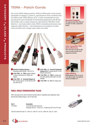
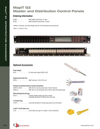
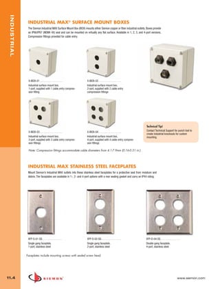
TERA S/FTP 1000 MHz
4-Pair Cable (US)
COMPLIANCE
• ISO/IEC 11801:2002 (Category 7) Part # Description
• ISO/IEC 11801 Amendment 1 (draft) 9T7P4-E10-06-R1. . . . . . . . . . . Plenum (CMP, CSA FT6), Blue Jacket,
• IEC 61156-5:2002 (Category 7) 305m (1000 ft.) Reel
• IEC 61156-5 Ed 2.0 (Category 7A) 9T7R4-E10-06-R1. . . . . . . . . . . Riser (CMR, CSA FT4), Blue Jacket,
• UL CMR and CSA FT4 305m (1000 ft.) Reel
• UL CMP and CSA FT6
CABLE CONSTRUCTION
• S/FTP
• 0.64mm (0.025 in.) (22 AWG) solid bare copper
• 8.9mm (0.35 in.) [CMR], 8.4mm (0.33 in.) [CMP]
max jacket diameter
• Pairs individually shielded with aluminum-polyester foil
• Overall tinned copper braid
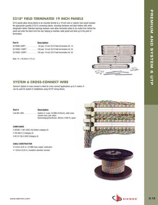
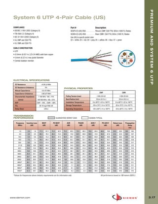
ELECTRICAL SPECIFICATIONS
DC Resistance <17.0 Ω/100m
DC Resistance Unbalance 2%
Mutual Capacitance 5.6 nF/100m
PHYSICAL PROPERTIES
Capacitance Unbalance <330 pF/100m
Characteristic Impedance 1-100 MHz: 100 ± 15% CMP CMR
(ohms) 100-250 MHz: 100 ± 22% Pulling Tension (max) 110N (25 lbf) 110N (25 lbf)
250-1000 MHz: 100± 25% Bend Radius (min) 50mm (2.0 in.) 50mm (2.0 in.)
NVP 80% Installation Temperature 0 to 60°C (+32 to 140°F) 0 to 60°C (+32 to 140°F)
TCL 40-10 log(ƒ) dB Storage Temperature -20 to 75°C (-4 to 167°F) -20 to 75°C (-4 to 167°F)
Delay Skew ≤20ns Operating Temperature -20 to 60°C (-4 to 140°F) -20 to 60°C (-4 to 140°F)
TRANSMISSION PERFORMANCE GUARANTEED WORST CASE SIEMON TYPICAL
Frequency Insertion Loss NEXT PS NEXT ACR PSACR ACR-F PS ACR-F Return Loss Propagation
(MHz) (dB) (dB) (dB) (dB) (dB) (dB) (dB) (dB) Delay
(ns)
1.0* 2.1 1.7 78.0 100.0 75.0 97.0 75.9 98.3 72.9 95.3 78.0 90.0 75.0 87.0 20.0 30.0 512 492
4.0 3.7 3.4 78.0 100.0 75.0 97.0 74.3 96.6 71.3 93.6 78.0 90.0 75.0 87.0 23.0 33.0 494 474
10.0 5.8 5.0 78.0 100.0 75.0 97.0 72.2 95.0 69.2 92.0 74.0 90.0 71.0 87.0 25.0 35.0 487 467
16.0 7.3 6.4 78.0 100.0 75.0 97.0 70.7 93.6 67.7 90.6 69.9 90.0 66.9 87.0 25.0 35.0 485 465
20.0 8.2 7.1 78.0 100.0 75.0 97.0 69.8 92.9 66.8 89.9 68.0 90.0 65.0 87.0 25.0 35.0 484 464
31.25 10.3 9.0 78.0 100.0 75.0 97.0 67.7 91.0 64.7 88.0 64.1 90.0 61.1 87.0 23.6 33.6 482 462
62.5 14.6 13.0 75.5 100.0 72.5 97.0 60.9 87.0 57.9 84.0 58.1 85.0 55.1 82.0 21.5 31.5 481 461
100.0 18.5 16.8 72.4 98.0 69.4 95.0 53.9 81.2 50.9 78.2 54.0 81.0 51.0 78.0 20.1 30.1 480 460
200.0 26.5 23.9 67.9 93.0 64.9 90.0 41.4 69.1 38.4 66.1 48.0 77.0 45.0 74.0 18.0 28.0 479 459
250.0 29.7 28.5 66.4 92.1 63.4 89.1 36.7 63.6 33.7 60.6 46.0 76.0 43.0 73.0 17.3 27.3 478 458
300.0 32.7 29.2 65.2 91.0 62.2 88.0 32.6 61.8 29.6 58.8 44.5 71.0 41.5 68.0 17.3 27.3 478 458
350.0 35.4 31.8 64.2 90.3 61.2 87.3 28.8 58.5 25.8 55.5 43.1 69.0 40.1 66.0 17.3 27.3 478 458
400.0 38.0 33.4 63.4 89.1 60.4 86.1 25.4 55.7 22.4 52.7 42.0 68.1 39.0 65.1 17.3 27.3 478 458
550.0 45.0 37.2 61.3 87.3 58.3 84.3 16.3 50.1 13.3 47.1 39.2 66.2 36.2 63.1 17.3 27.3 478 458
600.0 47.1 42.5 60.7 86.1 57.7 83.1 13.6 43.6 10.6 40.6 38.4 60.0 35.4 57.0 17.3 27.3 477 458
800.0 54.9 48.2 58.9 83.1 55.9 80.1 3.9 34.9 0.9 31.9 35.9 52.1 32.9 49.1 16.1 27.3 477 457
900.0 58.5 53.8 58.1 82.0 55.1 79.0 -0.4 28.2 -3.4 25.2 34.9 48.0 31.9 45.0 15.5 25.0 477 456
1000.0 61.9 57.5 57.4 81.0 54.4 78.0 -4.5 23.5 -7.5 20.5 34.0 46.0 31.0 43.0 15.1 24.0 477 456
*Values below 4 MHz are for information only All performance based on 100 meters (328 ft.).
www.siemon.com 1.7](https://image.slidesharecdn.com/catalogo-siemon-120904141445-phpapp02/85/Catalogo-Siemon-da-Spark-Controles-12-320.jpg)

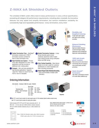
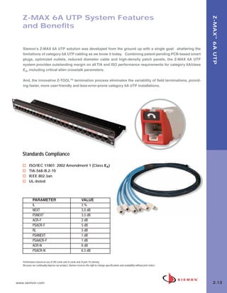
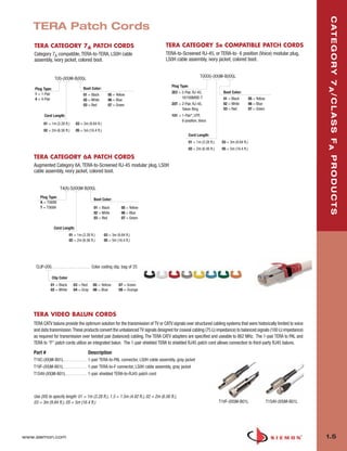
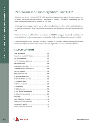
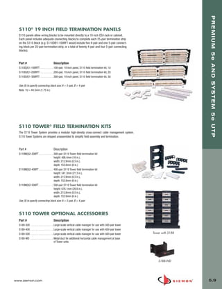
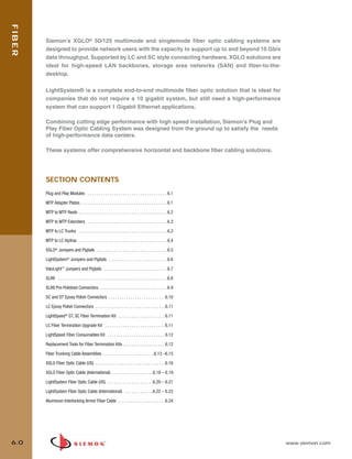
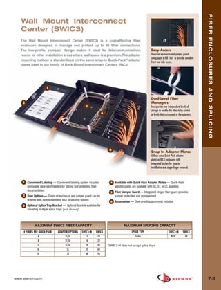
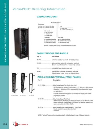
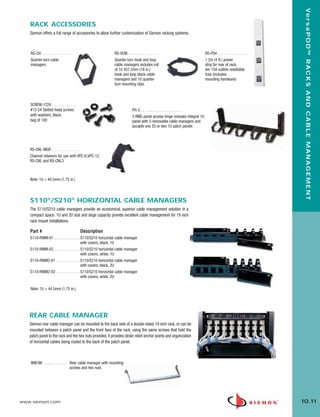
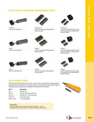
![03_Premium6_UTP.qxd:ZMax_Catalog 1/4/10 11:20 AM Page 5
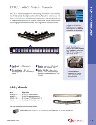
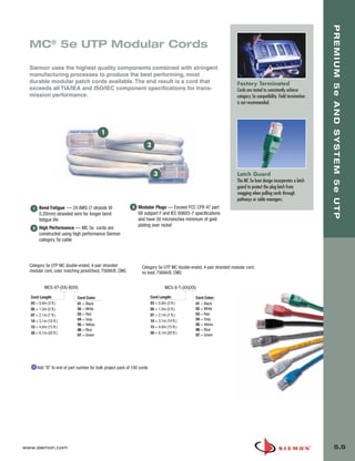
PREMIUM AND SYSTEM 6 UTP
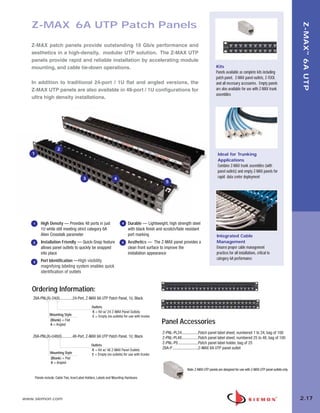
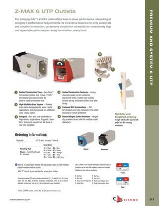
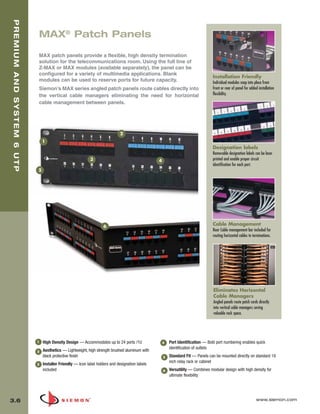
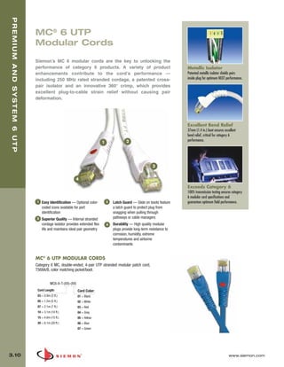
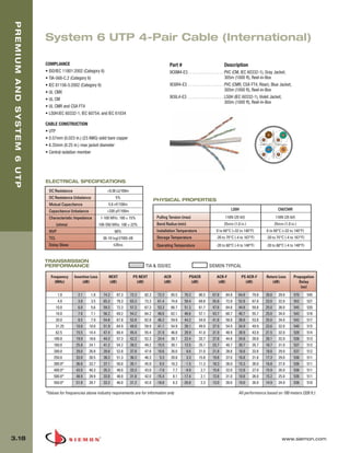
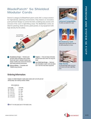
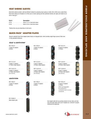
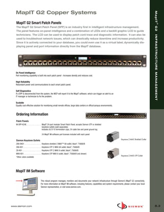
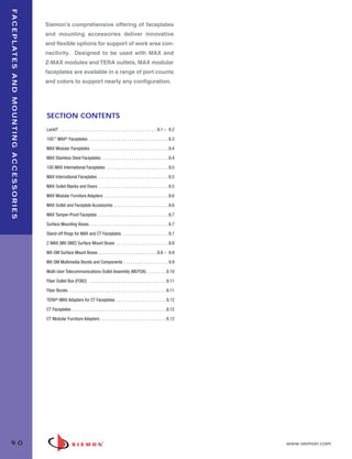
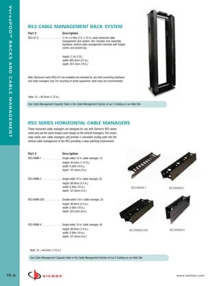
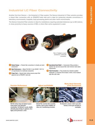
HD6 UTP Patch Panels
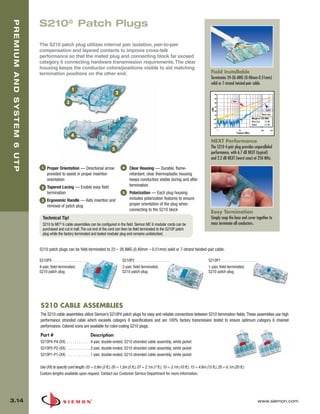
Siemon’s HD 6 patch panel was the industry’s first patch panel to
exceed category 6 connecting hardware specifications for all pair
combinations up to 250 MHz. Get superior performance and user-
friendly termination, labeling, and cable management features with Pyramid™ Wire Entry
Siemon’s popular category 6 patch panel. System
Pyramid wire entry system on S310 blocks
separates paired conductors when lacing
cables to reduce installation time.
3
1
5
Circuit Protection
Rear metal enclosure protects printed
4 circuitry.
2
1 4
Cable Management
Universal Wiring — HD 6 patch panels Port Identification — Bold port numbering
Includes built-in cable manager to properly
feature universal wiring for both T568A/B enables quick identification of outlets
guide cables to point of termination.
2 Aesthetics — Front surface is uninterrupted 5 Standard Fit — Panels can be mounted
by screw heads for a clean appearance directly on standard 19 inch relay rack or
cabinet
3 Installer Friendly — Icon label holders and
designation labels included
Ordering Information:
Part # Description
HD6-16 . . . . . . . . . . . . .16-port category 6 UTP HD patch panel, 1U
HD6-24 . . . . . . . . . . . . . 24-port category 6 UTP HD patch panel, 1U
HD6-48 . . . . . . . . . . . . . 48-port category 6 UTP HD patch panel, 2U
HD6-96 . . . . . . . . . . . . . 96-port category 6 UTP HD patch panel, 4U
Panels include rear cable manager(s), icon label holders, designation labels, cable ties, and mounting hardware.
Add “B” for bulk project pack of 5 panels (rear cable managers [p/n: HD-RWM] not included but can be ordered separately).
Note: 1U = 44.5mm (1.75 in.)
S310 termination blocks are not compatible with S110® multi-pair termination tools.
3.4 www.siemon.com](https://image.slidesharecdn.com/catalogo-siemon-120904141445-phpapp02/85/Catalogo-Siemon-da-Spark-Controles-39-320.jpg)


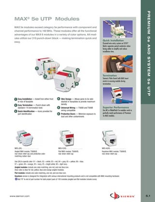
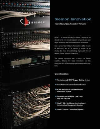
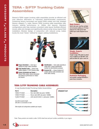
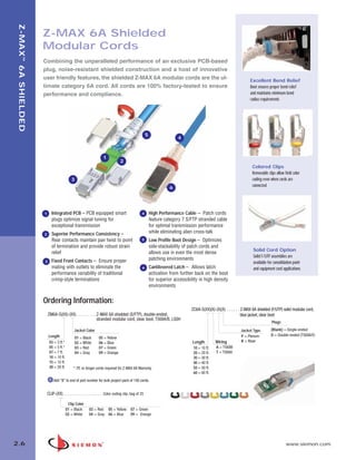
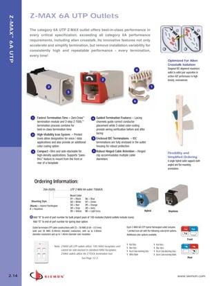
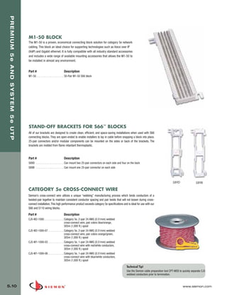
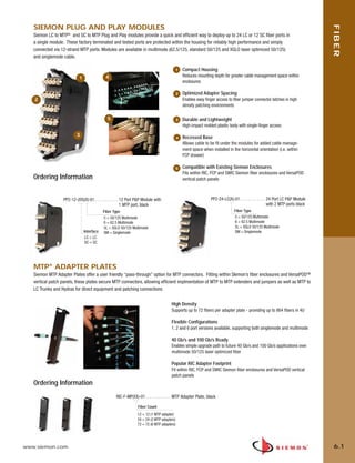
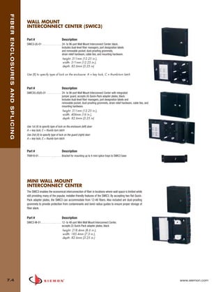
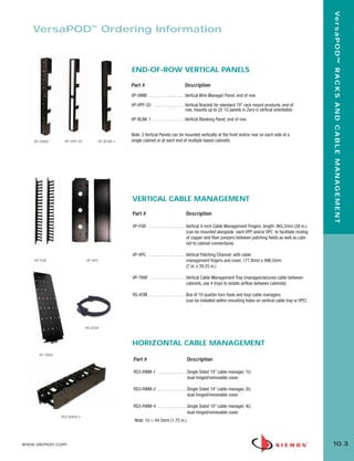
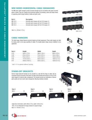
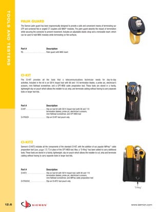
![05_Premium_Sys_5E_UTP.qxd:ZMax_Catalog 1/8/10 9:12 AM Page 4
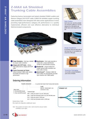
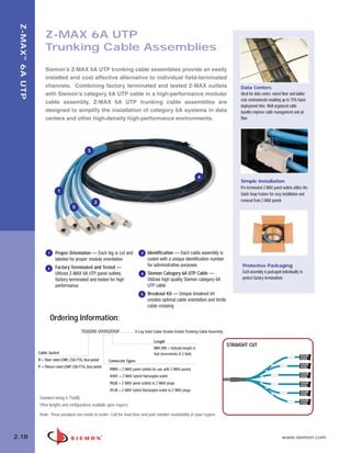
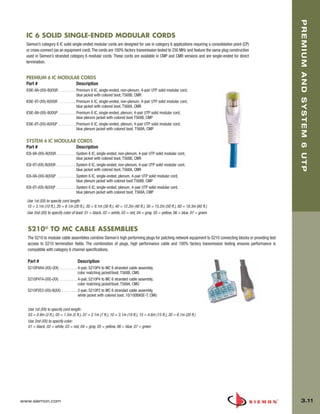
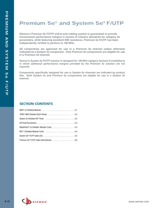
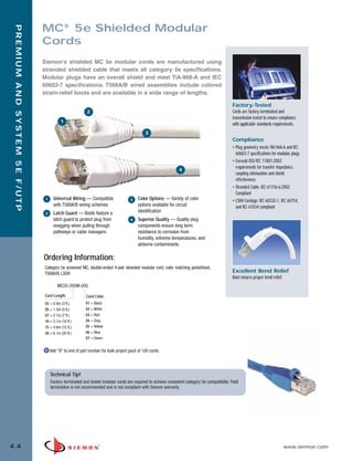
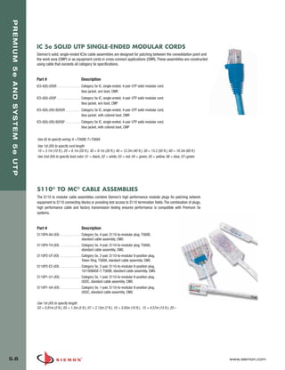
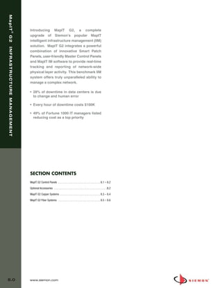
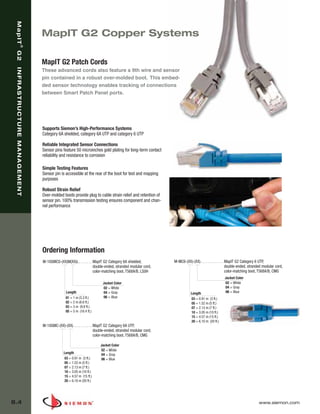
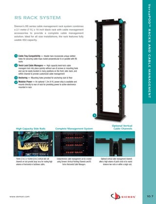
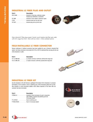
HD® 5e UTP Patch Panels
PREMIUM 5e AND SYSTEM 5e UTP
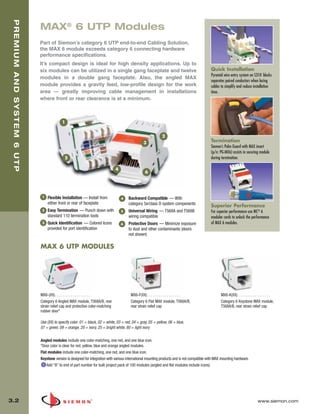
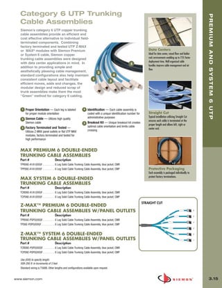
Siemon’s HD 5e series patch panels offer the most robust category 5e
patching solution in the industry. HD 5e panels feature universal T568A/B
wiring and exceed category 5e requirements with component and chan-
Compliant Pin
nel performance to 160 MHz. Compliant pin technology enables the use
Technology
of multi-pair S110® punch-down tools to reduce termination time.
Allows the use of Siemon’s multi-pair
impact tool to significantly reduce
termination time. S110 termination
2
1 opening on the rear are compatible with
4 S110 patch plugs.
5
3
Rear Cable Management
Integrated rear cable manager properly
guides cables to and from the rear of the
panel.
1 Universal Wiring — HD 5e patch panels 4 Port Identification — Bold port numbering
feature universal wiring for both T568A/B enables quick identification of outlets
2 Aesthetics — Front surface is uninterrupted 5 Standard Fit — Panels can be mounted
by screw heads for a clean appearance directly on standard 19 inch relay rack or
Installer Friendly — Panels available in cabinet
3
Quick Identification
16-, 24-, 48- and 96-port configurations
Icon and label holder kits are included with
every panel.
Ordering Information:
HD 5e UTP PATCH PANELS
PART # Description
HD5-16 . . . . . . . . . . . . . 16-port category 5e UTP HD patch panel, T568A/B, 1U
HD5-24 . . . . . . . . . . . . . 24-port category 5e UTP HD patch panel, T568A/B, 1U
HD5-32 . . . . . . . . . . . . . 32-port category 5e UTP HD patch panel, T568A/B, 2U
HD5-48 . . . . . . . . . . . . . 48-port category 5e UTP HD patch panel, T568A/B, 2U
HD5-96 . . . . . . . . . . . . . 96-port category 5e UTP HD patch panel, T568A/B, 4U
Panels include rear cable manager, icon/label holders, designation labels, cable ties, and
mounting hardware.
Add “B” for bulk project pack of 5 panels (rear cable managers (p/n: HD-RWM] not included
but can be ordered separately).
Note: 1U = 44.5mm (1.75 in.)
16- and 32-port HD 5e panels feature S310 termination blocks.
S310 termination blocks are not compatible with S110 multi-pair termination tools.
HD 5e UTP PATCH PANEL ON S89D BRACKET
Part # Description
HD5-89D-12 . . . . . . . . . . . . . . . 12-port category 5e UTP panel, T568A/B, mounted on S89D
bracket
height: 254.0mm (10.0 in.),
width: 85.9mm (3.38 in.),
depth: 47.8mm (1.88 in.)
www.siemon.com 5.3](https://image.slidesharecdn.com/catalogo-siemon-120904141445-phpapp02/85/Catalogo-Siemon-da-Spark-Controles-66-320.jpg)

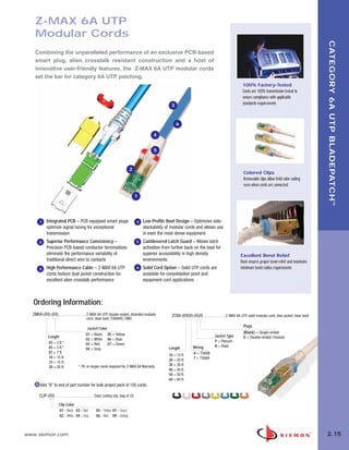
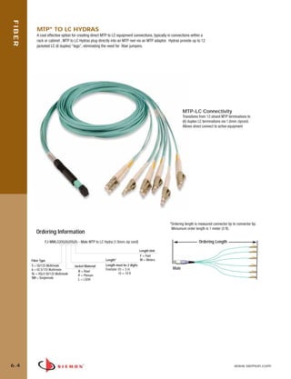
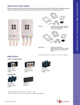
![06_Fiber_Cble_Asmbly_RevB.qxd:ZMax_Catalog 2/12/10 3:28 PM Page 4
MTP® TO MTP EXTENDERS
FIBER
Constructed with Siemon’s reduced-diameter RazorCoreTM cable, extenders offer Male MTP Connectors on one
end and female MTP on the other to allow field extension of MTP Reels. Available in 12-144 fiber versions as
well as multimode (standard 50/125, 62.5/125, XGLO 50/125) and singlemode fiber types.
Ordering Information
FE(XXX)-(XX)(X)(XXX)(X). . . . . . . .P&P extender, Male MTP to Female MTP
Length Unit *Ordering length is measured connector tip to connector
Fiber Count F = Feet tip. Multi-leg versions offered with standard 1 meter
12 =12 M = Meters (3.3 ft) legs. Minimum order length is 3 meters (10 ft).
24 =24
36 =36
48 =48 Fiber Type Length*
72 =72
Ordering Length
5 = 50/125 Multimode Jacket Rating
Length must be 3 digits
96 =96 6 = 62.5/125 Multimode Example: 003 = 3 m
144 =144 R =Riser 010 = 10 ft
5L = XGLO 50/125 Multimode
P =Plenum
SM = Singlemode L =LSOH
Male Female
MTP® TO LC TRUNKS
Utilizing high quality Siemon RazorCore cable, MTP to LC Trunks offer a connectivity transition from 12-fiber MTP connectors to duplex LC
connectors. These may be implemented with Siemon’s MTP Adapter Plates to provide flexible direct MTP to LC patching options over a
wide a range of distances and infrastructure configurations.
Custom Configurations
Available from 12 to 144 fiber counts in increments of 12 fibers
Multiple Fiber Types
Available in mulitmode (62.5/125, standard 50/125 and laser optimized 50/125)
and singlemode. Jacket ratings in riser, plenum and LSOH
Protective Packaging
Dual shelf reel keeps connectivity protected during payout
Ordering Information
TF(X)(X)(XX)(X)(XX)LC(XXX)(X). . . . . . . . . . MTP - LC Trunk (distribution to breakout)
Fiber Count Length Unit
B = 12 F = Feet *Ordering length is measured con-
C = 24 Pulling Eye Length* M = Meters nector tip to connector tip. Jacketed
E = 36 A = Side A Length must be 3 digits duplex LC legs offered in standard
F = 48 B = Side B Example: 003 = 3 m 1 meter (3.3 ft) length. Miniumum
G = 72 C = None
010 = 10 ft order length is 3 meters (10ft).
H = 96
MTP Connector Gender
J = 144
MM = Male
MF = Female
Jacket Rating Ordering Length
Fiber Type R = Riser
P = Plenum 1 meter (3.3 ft)
5 = 50/125 Multimode
L = LSOH
6 = 62.5/125 Multimode
5L = XGLO 50/125 Multimode
SM = Singlemode
RazorCore Cable Diameter
Fiber Count 12 24 36 48 72 96 144
Cable Diameter
inches [mm] 0.12 [3.0] 0.25 [6.4] 0.29 [7.3] 0.29 [7.3] 0.33 [8.4] 0.52 [13.2] 0.52 [13.2]
www.siemon.com 6.3](https://image.slidesharecdn.com/catalogo-siemon-120904141445-phpapp02/85/Catalogo-Siemon-da-Spark-Controles-80-320.jpg)
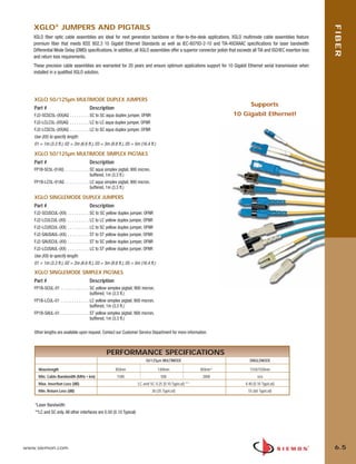
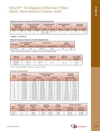
![06_Fiber_Cble_Asmbly_RevB.qxd:ZMax_Catalog 2/12/10 3:29 PM Page 17
FIBER
XGLO® 10 Gigabit Ethernet
Fiber Optic Distribution Cable (US)
SINGLEMODE, YELLOW JACKET
PART # FIBER COUNT CONSTRUCTION
9BB8(X)002B-E205A . . . . . . . . . . . . . . . . . 2 . . . . . . . . . . . . . . . . 1 tube of 2 fibers
9BB8(X)004C-E205A . . . . . . . . . . . . . . . . . 4 . . . . . . . . . . . . . . . . 1 tube of 4 fibers
9BB8(X)006D-E205A . . . . . . . . . . . . . . . . . 6 . . . . . . . . . . . . . . . . 1 tube of 6 fibers
9BB8(X)008E-E205A. . . . . . . . . . . . . . . . . . 8 . . . . . . . . . . . . . . . . 1 tube of 8 fibers
9BB8(X)012G-E205A. . . . . . . . . . . . . . . . . . 12 . . . . . . . . . . . . . . . 1 tube of 12 fibers
9BB8(X)016C-E205A. . . . . . . . . . . . . . . . . . 16 . . . . . . . . . . . . . . . 4 tubes of 4 fibers
12 Fiber Singlemode
9BB8(X)024L-E205A. . . . . . . . . . . . . . . . . . 24 . . . . . . . . . . . . . . . 1 tube of 24 fibers
9BB8(X)036D-E205A . . . . . . . . . . . . . . . . . 36 . . . . . . . . . . . . . . . 6 tubes of 6 fibers
9BB8(X)048G-E205A. . . . . . . . . . . . . . . . . . 48 . . . . . . . . . . . . . . 4 tubes of 12 fibers
9BB8(X)072G-E205A. . . . . . . . . . . . . . . . . . 72 . . . . . . . . . . . . . . 6 tubes of 12 fibers
Use (X) to specify cable rating: R = OFNR, P = OFNP
24 Fiber Singlemode
50/125µm MULTIMODE LASER OPTIMIZED, AQUA JACKET
PART # FIBER COUNT CONSTRUCTION
9BB5(X)002B-T312A . . . . . . . . . . . . . . . . . 2 . . . . . . . . . . . . . . . . 1 tube of 2 fibers
9BB5(X)004C-T312A . . . . . . . . . . . . . . . . . 4 . . . . . . . . . . . . . . . . 1 tube of 4 fibers
9BB5(X)006D-T312A . . . . . . . . . . . . . . . . . 6 . . . . . . . . . . . . . . . . 1 tube of 6 fibers
9BB5(X)008E-T312A. . . . . . . . . . . . . . . . . . 8 . . . . . . . . . . . . . . . . 1 tube of 8 fibers 12 Fiber Multimode
9BB5(X)012G-T312(Y). . . . . . . . . . . . . . . . . 12 . . . . . . . . . . . . . . . 1 tube of 12 fibers
9BB5(X)016C-T312A. . . . . . . . . . . . . . . . . . 16 . . . . . . . . . . . . . . . 4 tubes of 4 fibers
9BB5(X)024L-T312(Y) . . . . . . . . . . . . . . . . . 24 . . . . . . . . . . . . . . . 1 tube of 24 fibers
9BB5(X)036D-T312A . . . . . . . . . . . . . . . . . 36 . . . . . . . . . . . . . . . 6 tubes of 6 fibers
9BB5(X)048G-T312A. . . . . . . . . . . . . . . . . . 48 . . . . . . . . . . . . . . 4 tubes of 12 fibers
9BB5(X)072G-T312A. . . . . . . . . . . . . . . . . . 72 . . . . . . . . . . . . . 6 tubes of 12 fibers
24 Fiber Multimode
Use (X) to specify cable rating: R = OFNR, P = OFNP
Use (Y) to specify reel length: 1 = 1000 ft. (305m) reel, A = Reel length
greater than 1000 ft. (305m)
COMPLIANCE CABLE CONSTRUCTION
• ISO/IEC 11801:2002 (OM3) [MM] • Tight buffer design reduces cable OD and pathway space
• ISO/IEC 11801:2002 (OS1) [SM] requirements
• TIA-568-C.3 • Flexible, lightweight for ease of installation
• TIA-598-C • Thermoplastic outer and inner (sub-unit) jackets
• IEC-60793-2-10 [MM] • Aramid yarn strength members
• TIA-492AAAC laser bandwidth DMD specification [MM] • Dielectric central strength member
• IEC 60793-2-49 and TIA/EIA 455-220 DMD measurement test • Color coded per TIA-598-C
procedures [MM]
• ITU-T G.652.C [SM]
• OFNR: Communications Type OFNR (UL) and CSA FT4 c(UL)
• OFNP: Communications Type OFNP (UL) and CSA FT6 c(UL)
6 FIBER 12 FIBER 24 FIBER 48 FIBER 72 FIBER
6.16 www.siemon.com](https://image.slidesharecdn.com/catalogo-siemon-120904141445-phpapp02/85/Catalogo-Siemon-da-Spark-Controles-93-320.jpg)
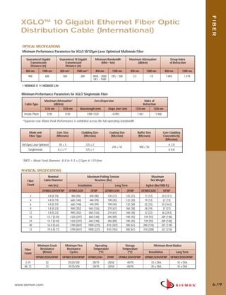
![06_Fiber_Cble_Asmbly_RevB.qxd:ZMax_Catalog 2/12/10 3:29 PM Page 19
FIBER
XGLO® 10 Gigabit Ethernet Fiber Optic
Distribution Cable (International)
SINGLEMODE, YELLOW JACKET
PART # FIBER COUNT CONSTRUCTION
9F8LB(X)-2F(XXXX) . . . . . . . . . . . . . . . . . . . 2 . . . . . . . . . . . . . . . . 1 tube of 2 fibers
9F8LB(X)-4A(XXXX). . . . . . . . . . . . . . . . . . . 4 . . . . . . . . . . . . . . . . 1 tube of 4 fibers
9F8LB(X)-6B(XXXX). . . . . . . . . . . . . . . . . . . 6 . . . . . . . . . . . . . . . . 1 tube of 6 fibers
9F8LB(X)-8C(XXXX). . . . . . . . . . . . . . . . . . . 8 . . . . . . . . . . . . . . . . 1 tube of 8 fibers
9F8LB(X)-12D(XXXX). . . . . . . . . . . . . . . . . . 12 . . . . . . . . . . . . . . . 1 tube of 12 fibers 12 Fiber Singlemode
9F8LB(X)-16A(XXXX) . . . . . . . . . . . . . . . . . . 16 . . . . . . . . . . . . . . . . 4 tube of 4 fibers
9F8LB(X)-24B(XXXX) . . . . . . . . . . . . . . . . . . 24 . . . . . . . . . . . . . . . 4 tubes of 6 fibers
9F8LB(X)-48D(XXXX). . . . . . . . . . . . . . . . . . 48 . . . . . . . . . . . . . . 4 tubes of 12 fibers
9F8LB(X)-72D(XXXX). . . . . . . . . . . . . . . . . . 72 . . . . . . . . . . . . . . 6 tubes of 12 fibers
50/125µm MULTIMODE LASER OPTIMIZED, AQUA JACKET
24 Fiber Singlemode
PART # FIBER COUNT CONSTRUCTION
9F5LB(X)-2F(XXXX) . . . . . . . . . . . . . . . . . . . 2 . . . . . . . . . . . . . . . . 1 tube of 2 fibers
9F5LB(X)-4A(XXXX). . . . . . . . . . . . . . . . . . . 4 . . . . . . . . . . . . . . . . 1 tube of 4 fibers
9F5LB(X)-6B(XXXX). . . . . . . . . . . . . . . . . . . 6 . . . . . . . . . . . . . . . . 1 tube of 6 fibers
9F5LB(X)-8C(XXXX). . . . . . . . . . . . . . . . . . . 8 . . . . . . . . . . . . . . . . 1 tube of 8 fibers
9F5LB(X)-12D(XXXX). . . . . . . . . . . . . . . . . . 12 . . . . . . . . . . . . . . . 1 tube of 12 fibers
9F5LB(X)-16A(XXXX) . . . . . . . . . . . . . . . . . . 16 . . . . . . . . . . . . . . . . 4 tube of 4 fibers 12 Fiber Laser Optimized Multimode
9F5LB(X)-24B(XXXX) . . . . . . . . . . . . . . . . . . 24 . . . . . . . . . . . . . . . 4 tubes of 6 fibers
9F5LB(X)-48D(XXXX). . . . . . . . . . . . . . . . . . 48 . . . . . . . . . . . . . . 4 tubes of 12 fibers
9F5LB(X)-72D(XXXX). . . . . . . . . . . . . . . . . . 72 . . . . . . . . . . . . . . 6 tubes of 12 fibers
Use (X) to specify cable rating: 1 = OFNR, 2 = OFNP, 3 = LS0H
Use (XXXX) to specify length in kilometer, use four characters including deci-
mal point. The last “X” must be a zero (0) or five (5) only.
Example p/n: 9F5LB1-12D1.50:
(1.5 kilometers [1500 meters] of 50/125µm laser optimized 12-strand riser 24 Fiber Laser Optimized Multimode
rated fiber optic cable)
For orders of less than 1 km, the first “X” must be zero (0).
Example: 9F5LB1-12D0.55 (.550 kilometers [550 meters] of 50/125µm
laser optimized 12-strand riser rated fiber optic cable)
COMPLIANCE
• ISO/IEC 11801:2002 2nd Edition (OM3) [MM] CABLE CONSTRUCTION
• ISO/IEC 11801:2002 2nd Edition (OS1) [SM] • Tight buffer design reduces cable OD and pathway space requirements
• TIA-568-C.3 • Flexible, lightweight for ease of installation
• TIA-598-C • Thermoplastic outer and inner (sub-unit) jackets
• IEC-60793-2-10 [MM] • Aramid yarn strength members
• TIA-492AAAC laser bandwidth DMD specification [MM] • Dielectric central strength member
• IEC 60793-2-49 and TIA/EIA 455-220 DMD measurement test procedures [MM] • Color coded per TIA-598-C
• ITU-T G.652.C [SM]
• LSOH:IEC 60332-1, IEC 61034, IEC 60754
• OFNR: Communications Type OFNR (UL) and CSA FT4 c(UL)
• OFNP: Communications Type OFNP (UL) and CSA FT6 c(UL)
6 FIBER 12 FIBER 24 FIBER 48 FIBER 72 FIBER
6.18 www.siemon.com](https://image.slidesharecdn.com/catalogo-siemon-120904141445-phpapp02/85/Catalogo-Siemon-da-Spark-Controles-95-320.jpg)
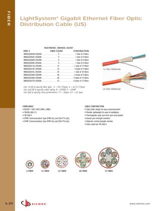
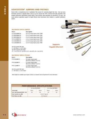
![06_Fiber_Cble_Asmbly_RevB.qxd:ZMax_Catalog 2/12/10 3:30 PM Page 23
FIBER
LightSystem® Gigabit Ethernet Fiber Optic
Distribution Cable (International)
MULTIMODE, ORANGE JACKET
PART # FIBER COUNT CONSTRUCTION
9F(X)B(X)-2F(XXXX) . . . . . . . . . . . . . . . . . . . 2 . . . . . . . . . . . . . . . . 1 tube of 2 fibers
9F(X)B(X)-4A(XXXX). . . . . . . . . . . . . . . . . . . 4 . . . . . . . . . . . . . . . . 1 tube of 4 fibers
9F(X)B(X)-6B(XXXX). . . . . . . . . . . . . . . . . . . 6 . . . . . . . . . . . . . . . . 1 tube of 6 fibers
9F(X)B(X)-8C(XXXX). . . . . . . . . . . . . . . . . . . 8 . . . . . . . . . . . . . . . . 1 tube of 8 fibers
9F(X)B(X)-12D(XXXX). . . . . . . . . . . . . . . . . . 12 . . . . . . . . . . . . . . . 1 tube of 12 fibers
12 Fiber Multimode
9F(X)B(X)-16A(XXXX) . . . . . . . . . . . . . . . . . . 16 . . . . . . . . . . . . . . . 4 tubes of 4 fibers
9F(X)B(X)-24B(XXXX). . . . . . . . . . . . . . . . . . 24 . . . . . . . . . . . . . . . 4 tubes of 6 fibers
9F(X)B(X)-48D(XXXX). . . . . . . . . . . . . . . . . . 48 . . . . . . . . . . . . . . 4 tubes of 12 fibers
9F(X)B(X)-72D(XXXX). . . . . . . . . . . . . . . . . . 72 . . . . . . . . . . . . . . 6 tubes of 12 fibers
Use 1st (X) to specify fiber type: 5 = 50/125µm, 6 = 62.5/125µm 24 Fiber Multimode
Use 2nd (X) to specify cable rating: 1 = OFNR, 2 = OFNP, 3 = LS0H
Use (XXXX) to specify length in kilometer, use four characters including
decimal point. The last “X” must be a zero (0) or five (5) only.
Example p/n: 9F5B1-12D1.50:
(1.5 kilometers [1500 meters] of 50/125µm 12-strand riser rated fiber optic cable)
For orders of less than 1 km, the first “X” must be zero (0).
Example: 9F5B1-12D0.55 (.550 kilometers [550 meters] of 50/125µm
12-strand riser rated fiber optic cable)
COMPLIANCE CABLE CONSTRUCTION
• ISO/IEC 11801:2002 (OM1), (OM2) • Tight buffer design for easy connectorization
• TIA-568-C.3 • Flexible, lightweight for ease of installation
• TIA-598-C • Thermoplastic outer and inner (sub-unit) jackets
• LS0H: IEC 60332-1, IEC 61034, IEC 60754 • Aramid yarn strength members
• Communications Type OFNR (UL) and CSA FT4 c(UL) • Dielectric central strength member
• Communications Type OFNP (UL) and CSA FT6 c(UL) • Color coded per TIA-598-C
6 FIBER 12 FIBER 24 FIBER 48 FIBER 72 FIBER
6.22 www.siemon.com](https://image.slidesharecdn.com/catalogo-siemon-120904141445-phpapp02/85/Catalogo-Siemon-da-Spark-Controles-99-320.jpg)

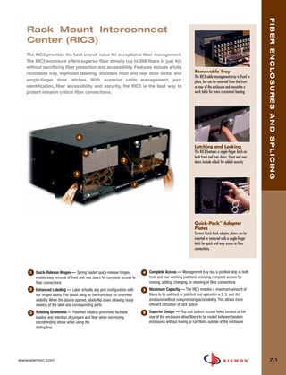
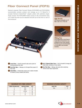
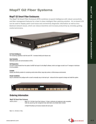

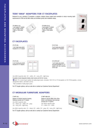
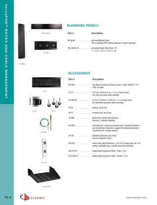
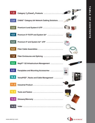
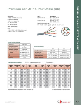
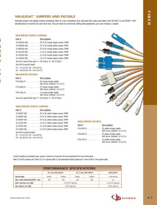
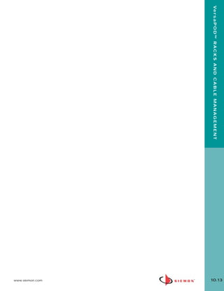
![10_RCM.qxd:RCM 1/26/10 2:28 PM Page 9
Ve r s a P O D ™ R A C K S A N D C A B L E M A N A G E M E N T
RS RACK SYSTEM
Part # Description
RS-07-S . . . . . . . . . . . . . . . . . . 2.1m x 0.48m (7 ft. x 19 in.) steel cable
management rack system, 45U. Includes: rack assembly
hardware, 10 high-capacity cable managers, 10 hook
and loop cable managers, grommets, and ground lug
height: 2.1m (7 ft.),
width: 609.6mm (24 in.),
depth: 457.2mm (18 in.)
Note: Aluminum racks are available (P/N: RS-07) and intended for use with connecting hardware and
cable managers only. For mounting of active equipment, steel racks are recommended.
See Cable Management Capacity Table in the Cable Management Section of our E-Catalog on our Web Site
EXTENDED DEPTH RS RACK SYSTEM
Siemon has developed a rack for managing extra large volumes of horizontal cables. The new extended depth rack features
vertical channels which are 0.37m (14.5 in.) deep. These channels include multiple mounting holes allowing the user to
configure Siemon’s twist-lock hook and loop cable managers for properly managing large individual bundles of cables. The
footers have also been designed to retain the 0.61m (24 in.) overall footprint.
Part # Description
RS-07E . . . . . . . . . . . . . . . . . . . 2.1m x 0.48m (7 ft. x 19 in.) aluminum
extra-deep (0.37m [14.5 in]) cable management
rack system, 45U. Includes rack assembly hardware,
10 high-capacity cable managers, 10 hook and
loop managers, grommets and ground lug.
height: 2.1m (7 ft.),
width: 609.6mm (24 in.),
depth: 609.6mm (24 in.)
Note: Aluminum racks are intended for use with connecting hardware and cable
managers only. For mounting of active equipment, steel racks such as RS-07-S are recommended.
See Cable Management Capacity Table in the Cable Management Section of our E-Catalog on our Web Site
RS SERIES HORIZONTAL CABLE MANAGERS
Siemon’s RS series cable managers are designed for use with Siemon’s RS-07 racks in conjunction with Siemon’s
vertical patching channel. The hinged cover extends across the vertical channels of the RS-07 to fully conceal patch cords
into the Vertical Patching Channel (VPC).
Part # Description RS-RWM-2
RS-RWM-2 . . . . . . . . . . . . . . . .Single-sided 19 in. cable manager, 2U
height: 88.9mm (3.5 in.),
width: 0.48m (19 in.),
depth: 101.6mm (4 in.)
RS-RWM-2DS . . . . . . . . . . . . . . Double-sided 19 in. cable manager, 2U
height: 88.9mm (3.5 in.),
0.48m (19 in.),
depth: 203.2mm (8 in.) RS-RWM-2DS
See Cable Management Capacity Table in the Cable Management Section of our E-Catalog on our Web Site
10.8 www.siemon.com](https://image.slidesharecdn.com/catalogo-siemon-120904141445-phpapp02/85/Catalogo-Siemon-da-Spark-Controles-141-320.jpg)
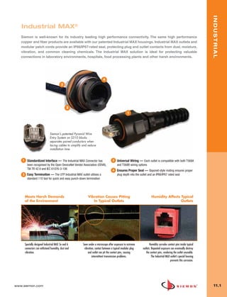
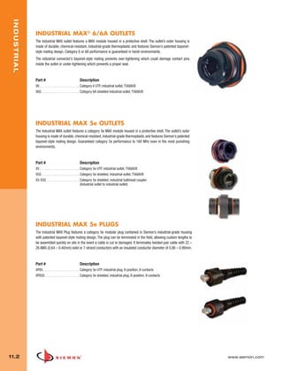
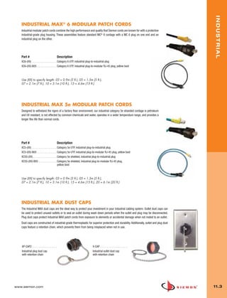


This document is a catalog for Siemon's networking cabling solutions. It introduces their TERA Category 7A/Class FA cabling system, which exceeds the specifications for Category 7A and Class FA and supports performance beyond 10Gb/s. The TERA system includes outlets, patch panels, patch cords, video baluns, trunking cables, and more. The catalog then outlines the various sections that describe Siemon's other cabling products like their Category 6A, Category 6, Category 5e, fiber optic cabling, infrastructure management solutions, faceplates, racks, and additional tools.


![5G Explained! A High Level Overview [Introduction]](https://cdn.slidesharecdn.com/ss_thumbnails/5gexplainedahighleveloverview-260119165306-cc137a3e-thumbnail.jpg?width=640&height=640&fit=bounds)


