Download to read offline

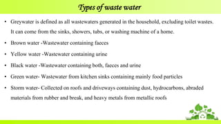
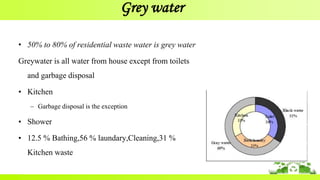
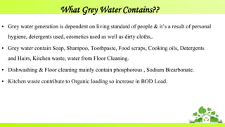
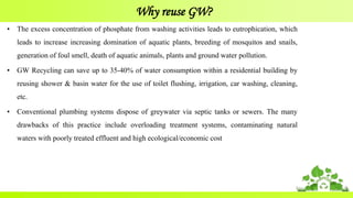
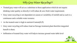
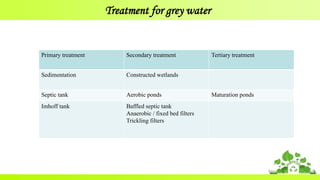
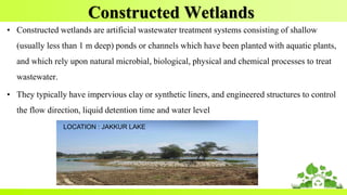
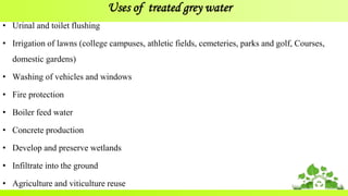
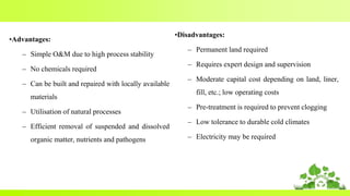

The document discusses grey water treatment using constructed wetlands, which are effective in recycling wastewater from household activities excluding toilet waste. Grey water constitutes 50-80% of residential wastewater, containing a range of contaminants such as soap, food scraps, and detergents; its treatment through constructed wetlands provides environmental benefits such as pollution reduction and nutrient recycling. Constructed wetlands operate through various processes including microbial degradation and filtration, making them an efficient and sustainable solution for water management without requiring significant energy or chemicals.


