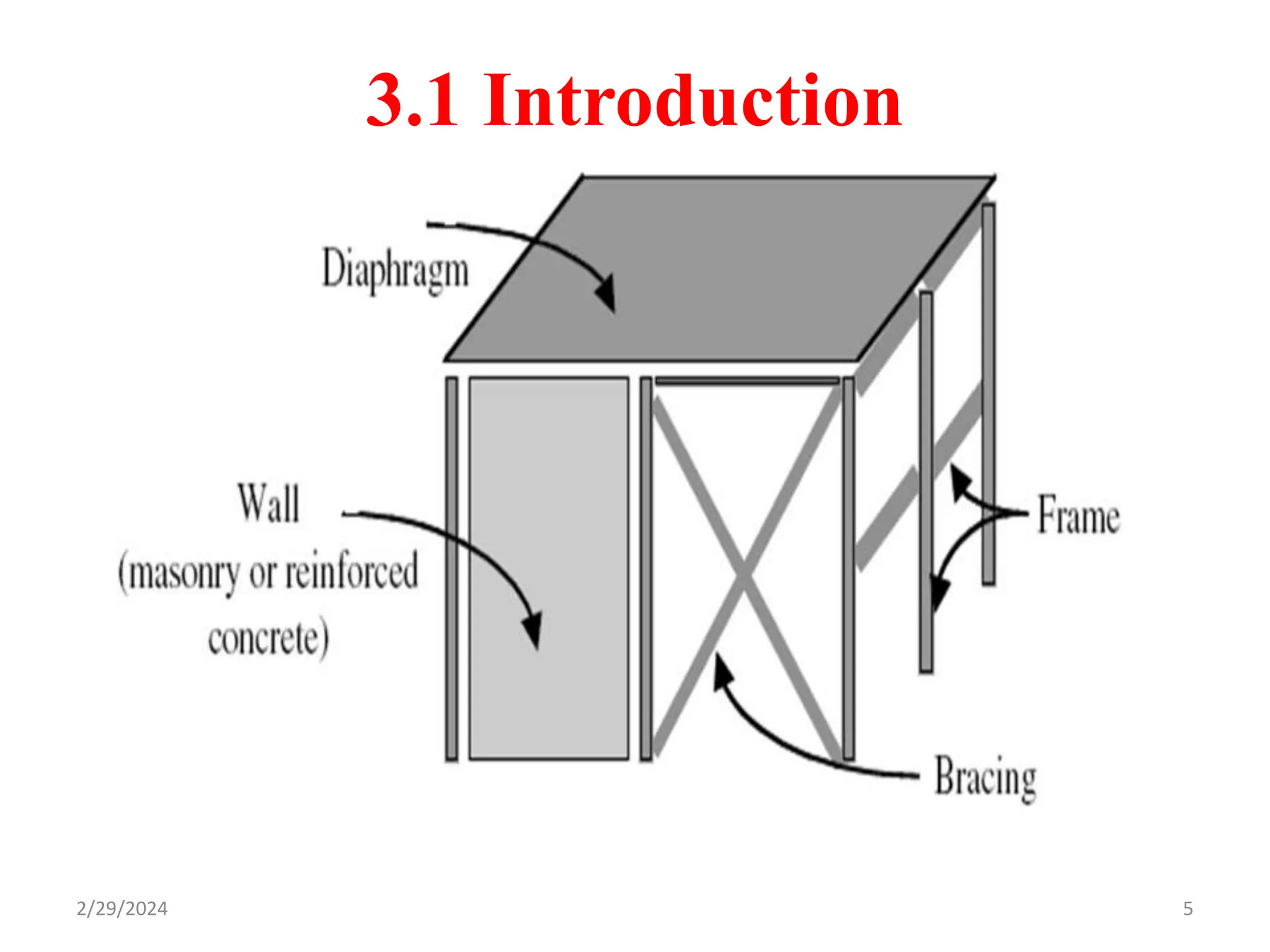
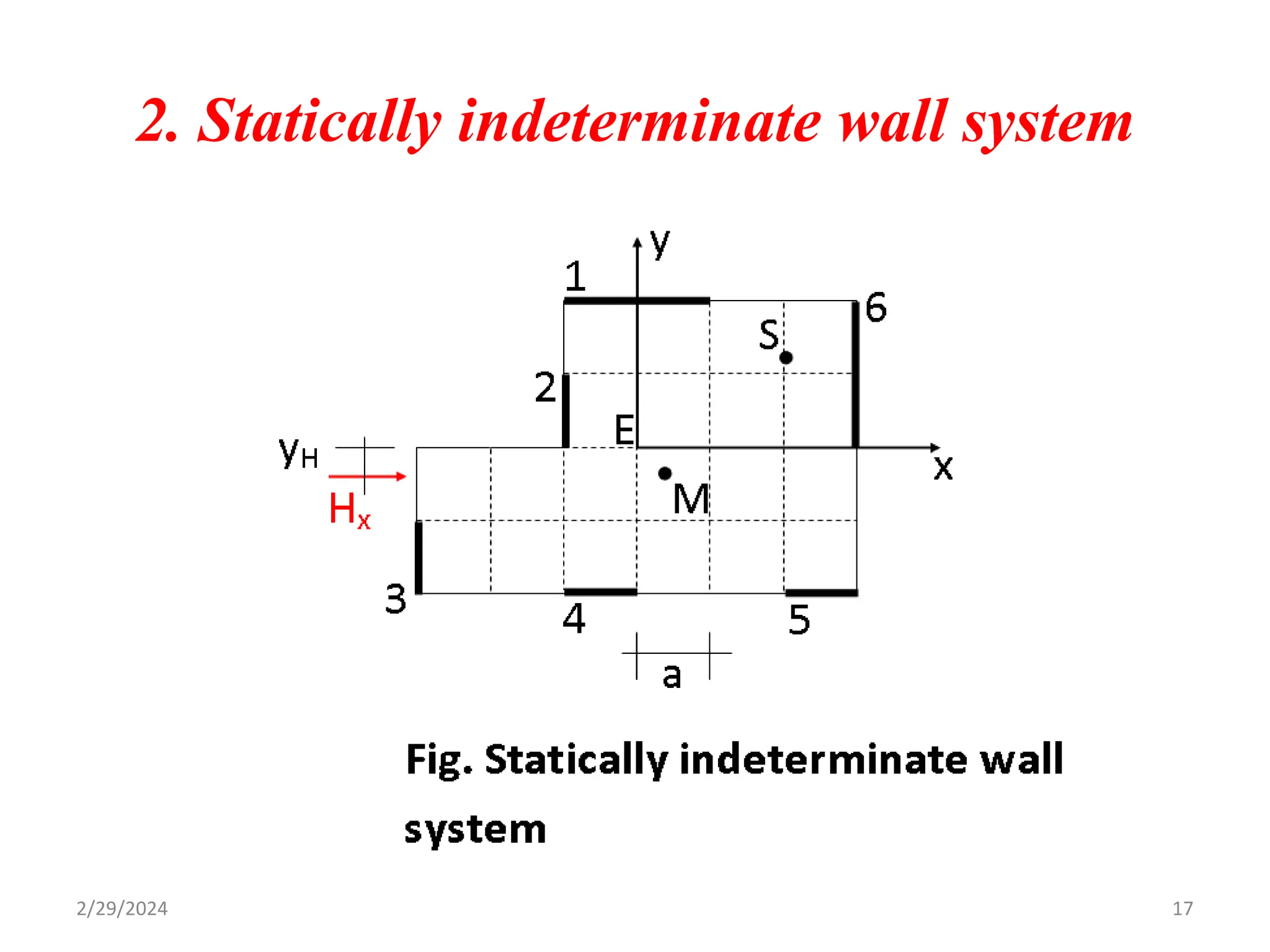
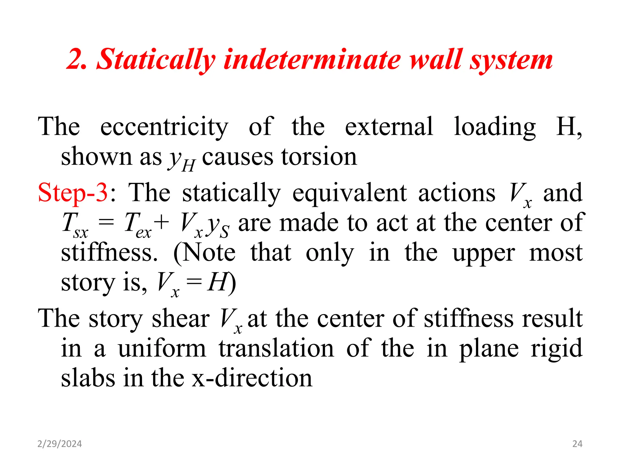
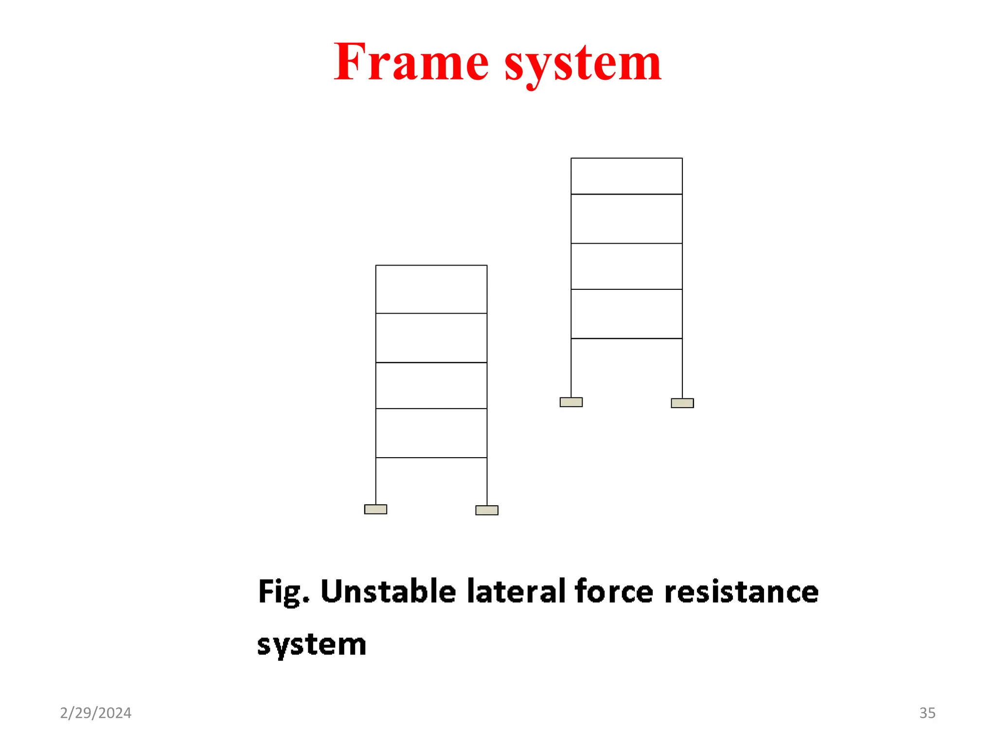
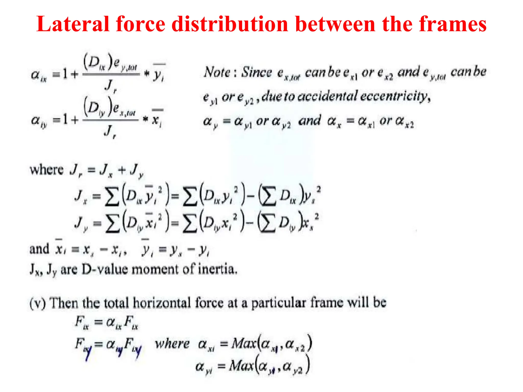
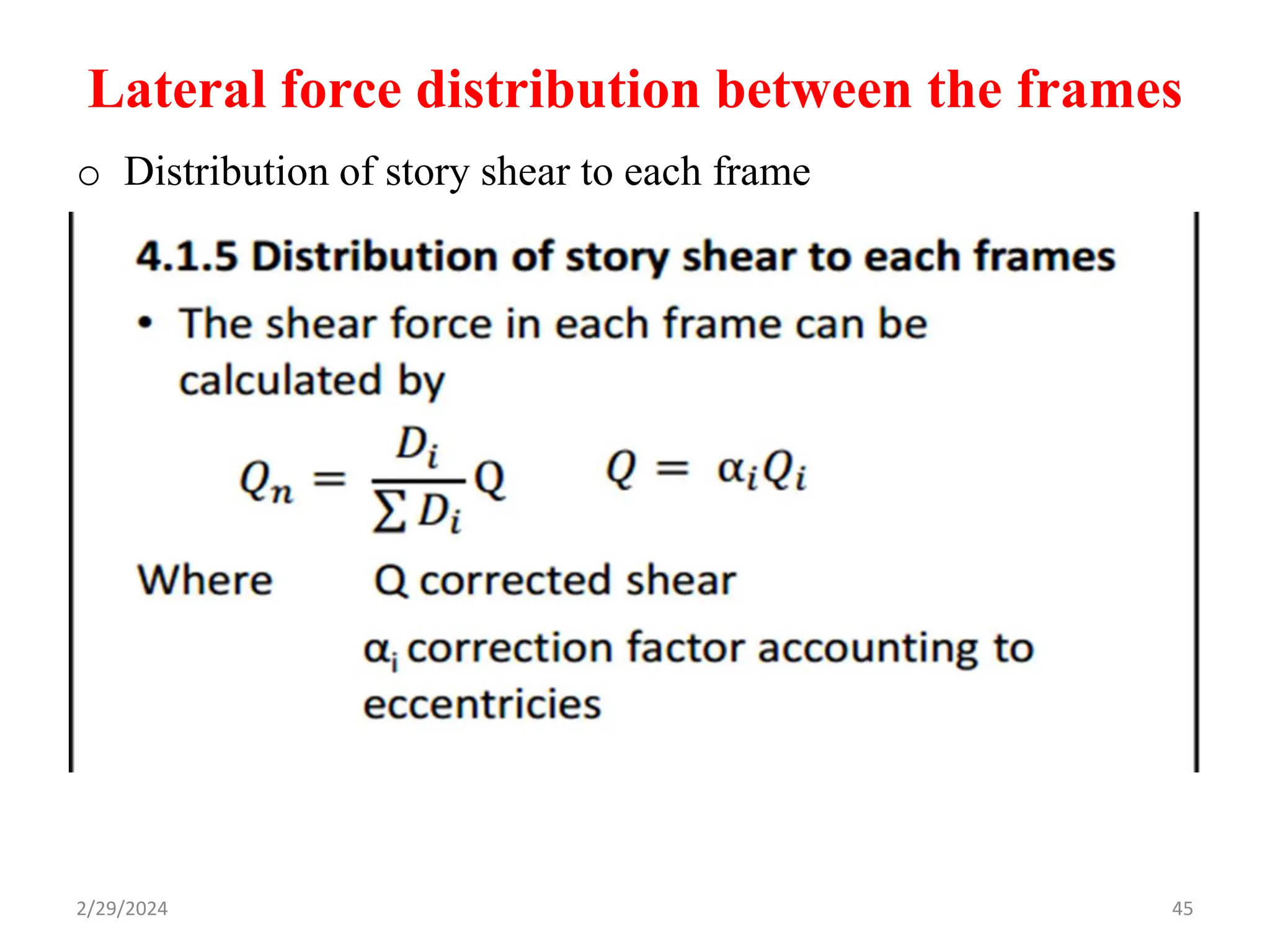
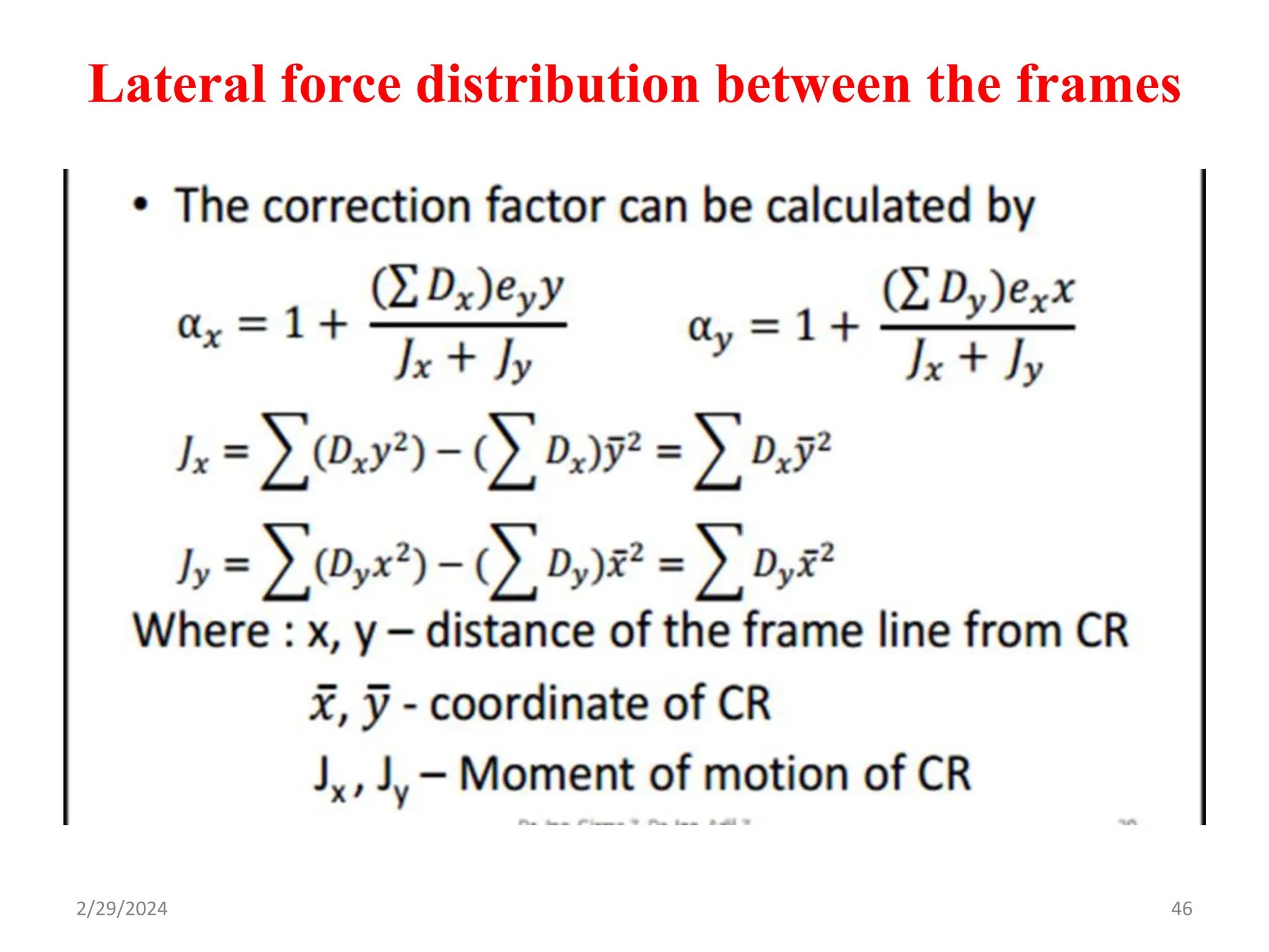
2. 3.1 Introduction
• All structures from the simplest to most
complex must be provided with suitable LFRS
• Simple structures such as isolated elevated
water tanks, sign boards, simple ware houses,
etc.
• More complex structures buildings, bridges,
waterfront structures, ships, etc.
2/29/2024 2
3. 3.1 Introduction
• A cantilever column or a pin supported column
with lateral restraint at ground level play the role
of LFRS for the similar structures.
• Elaborate LFRS consisting of frames, walls,
combinations of frames and walls, and other more
complex systems are required for the more
complex structures.
• In the latter the vertical elements are rigidly
connected with horizontal diaphragms enabling
them to act in unison.
2/29/2024 3
4. 3.1 Introduction
Horizontal diaphragms:
Consist of elements such as roofs, floor framing and/or the deck system having
sufficient strength and stiffness with rigid and useful planes.
Open rigid frames:
Consist of beams and columns framed together to produce moment resisting
system and are the most flexible of the basic type of lateral resistive system.
Braced frames:
Refers to the use of trussing or triangulation of the frame to achieve its lateral
stability. The trussing causes the lateral loads to induce only axial forces in the
members of the frame as compared to the behavior of rigid frame.
Vertical diaphragms:
Shear walls are walls of buildings and essentially function as lateral load resistive
system, Most common type includes: concrete masonry, wood shear walls, RC
shear walls.
2/29/2024 4
6. 3.1 Introduction
The most commonly used structural systems are:
(i) Wall systems
(ii) Frame systems
(iii) Mixed wall-frame system
6
2/29/2024
7. 3.2 Wall System
Stable arrangement of walls
(i) There must be at least 3 walls
(ii) The axes of the walls should not intersect
at a point
(iii) All the 3 walls should not be parallel
7
2/29/2024
9. Avoid high torsion
Note: eccentric arrangement of wall is the most
frequent cause of collapse during EQ
9
Cont…
2/29/2024
10. Distribution of story shear among the walls
1. Statically determinate wall system
• If there are only three walls.
10
2/29/2024
11. Cont…
Note: the story shear and the forces in the walls
are statically equivalent
V2x = 100 kN
V1y+ V3y = 0
Torsion exerted by the story shear Vx
V2x(5) + V3y(8) – V1y(10) = 0
V3y= -500/18 and V1y= 500/18
V3y= -27.78 kN and V1y= 27.78 kN
11
2/29/2024
12. Cont…
To reduce the magnitudes of the forces,
(i) reduce the magnitude of the torsional
moment 500 kNm by reducing the distance b/n
the story shear Vx and the center of stiffness S
that lies on wall axis of Wall 2 and
(ii) Increasing the lever arm b/n walls 1 and 3,
placing them as far apart from each other as
possible ,i.e., at the periphery
12
2/29/2024
13. 2. Statically indeterminate wall system
• More than three walls
• Additional compatibility conditions are to be considered to
determine all shear wall forces
Center of mass (Xm, Ym): it is a point on a floor level
where the whole floor mass and its inertial effects can be
replaced using a lumped equivalent mass (concentrated). It
is a point where the floor weight distribution is equal in all
directions. It is the average position of the floor’s system.
13
2/29/2024
14. 2. Statically indeterminate wall system
Center of seismic force: it is a point on a floor level where a
horizontal seismic force Fi passes through. This point is same
as the center of mass.
Center of stiffness (Xs, Ys): a point where the stiffness or
strength of the floor is concentrated.
it is the point through which the resultant of the restraining
forces of a system acts.
Shear center (Xi, Yi): a point where the center of stiffness
(shear center) of the ith shear wall or column is located.
Lever arm ( ): the distance between the center of
stiffness of the floor and the shear center of the ith shear wall
or column.
2/29/2024 14
15. 2. Statically indeterminate wall system
Real Eccentricities (ex, ey): the difference between the center
of mass and center of stiffness of the floor.
Accidental eccentricities (eax, eay):
eax =
eay =
2/29/2024 15
16. 2. Statically indeterminate wall system
Determination of the center of stiffness
In the following:
Iix = Moment of inertia of wall i w.r.t x-Axis
Iiy = Moment of inertia of wall i w.r.t y-Axis
xi , yi = Distance of shear center of wall i from
origin of chosen coordinate system
= Distance of shear center of wall i from
the center of stiffness
16
i
i y
x ,
2/29/2024
18. 2. Statically indeterminate wall system
Goal is to:
(i) determine the center of stiffness
(ii) distribute the horizontal force passing through
M
A shear force Vx through the center of stiffness S
results only in translation in the x-direction and
no rotation.
This means the same amount of deflection for all
walls connected with each other by means of the
diaphragm
18
2/29/2024
19. 2. Statically indeterminate wall system
Vx is distributed according to their stiffness
(rigidity)
according to the moment of inertias w.r.t the
y-axis
Note that the resultant of the distributed forces is
equal to Vx and passes through S.
S can be determined by determining Vx
19
etc
I
I
V
V
I
I
V
V
iy
y
x
x
iy
y
x
x ;
;
2
2
1
1
2/29/2024
20. 2. Statically indeterminate wall system
Line of action of Vx is yS away from E and given
by:
Substitution for Vix in terms of Vx from above
and factoring the constants and
simplifying yields:
20
x
i
ix
ix
i
ix
s
V
y
V
V
y
V
y
)
(
)
(
iy
i
iy
s
I
y
I
y
)
(
ix
x
V
V
2/29/2024
21. 2. Statically indeterminate wall system
Similarly from consideration of story shear Vy in
the y-direction
As an example determine the center of stiffness
of the statically indeterminate wall system
shown in the previous slide.
21
ix
i
ix
s
I
x
I
x
)
(
2/29/2024
22. 2. Statically indeterminate wall system
Solution: Let t = wall thickness
I1y = I6x = t(2a)3/12 ;
I2x = I3x = I4y = I5y = t(a)3/12,
I1x = I2y = I3y = I4x = I5x = I6 0
xS = 2.0a ; yS = 1.2a (check as an assignment)
It is shown as S in the floor plan
22
2/29/2024
23. 2. Statically indeterminate wall system
Story shear distribution among the walls
Step-1: External horizontal force H acts
generally eccentric to assumed origin of axis
(E). In the case of EQ it passes through the
mass center
Step-2 : Story shear determined and made to pass
through the origin of chosen axis (E).
23
2/29/2024
24. 2. Statically indeterminate wall system
The eccentricity of the external loading H,
shown as yH causes torsion
Step-3: The statically equivalent actions Vx and
Tsx = Tex+ Vx yS are made to act at the center of
stiffness. (Note that only in the upper most
story is, Vx = H)
The story shear Vx at the center of stiffness result
in a uniform translation of the in plane rigid
slabs in the x-direction
24
2/29/2024
25. 2. Statically indeterminate wall system
The story shear is distributed according to their
moments of inertias as discussed before.
The torsional moment TS results in rotation of the slabs
about the center of stiffness. It will be absorbed by all
the walls. (Observe the role of the diaphragms in
distribution the loads to the walls. W/o the slabs this
is not possible)
25
2/29/2024
26. 2. Statically indeterminate wall system
Some of these terms are negligible because of
negligible bending stiffness and V1x ,V2x ,…,V1y
, V2y , … are a result of torsion Ts
Observe that, the deflection components of the
walls are proportional to
26
)
(
)
( 2
2
1
1
2
2
1
1
x
V
x
V
y
V
y
V
T y
y
x
x
s
,
,
,
,
, 2
1
2
1 x
x
y
y
2/29/2024
27. 2. Statically indeterminate wall system
Thus the shear forces V1x ,V2x ,…,V1y ,V2y , … in
the walls as a result of torsional moment TS are
proportional to the moment of inertia and the
lever arm and therefore their product
Where k = the proportionality constant that has
to be determined so that we can determine the
wall forces resulting from torsion
27
1
1
1
1
1
1 ; x
I
k
V
y
I
k
V x
y
y
x
2/29/2024
28. 2. Statically indeterminate wall system
Invoking statical equivalency between story
torsion TS and and the sum of the torsional
moments exerted by the wall forces w.r.t. the
center of stiffness S:
28
2
2
2
2
2
2
1
1
2
2
2
2
1
1
i
ix
i
iy
s
x
x
y
y
s
x
I
y
I
k
T
x
I
k
x
I
k
y
I
k
y
I
k
T
2
2
i
ix
i
iy
s
x
I
y
I
T
k
2/29/2024
29. 2. Statically indeterminate wall system
Substituting the vale of k in wall force eqns as a
result of torsion above:
Note that V1y 0 for wall 1
Thus the total force in wall i resulting from Vx
and TS will be:
29
,
,.....
2
2
1
1
1
2
2
1
1
1
i
ix
i
iy
x
s
y
i
ix
i
iy
y
s
x
x
I
y
I
x
I
T
V
x
I
y
I
y
I
T
V
2/29/2024
30. 2. Statically indeterminate wall system
Note that the 1st term in the expression for Viy is
0 because Vy = 0
30
2
2
1
1
1
2
2
1
1
1 ;
i
ix
i
iy
x
s
ix
ix
y
y
i
ix
i
iy
y
s
iy
iy
x
x
x
I
y
I
x
I
T
I
I
V
V
x
I
y
I
y
I
T
I
I
V
V
2/29/2024
31. 2. Statically indeterminate wall system
Example 2:
For the Statically indeterminate walls distribute
the story shear if:
Hx = 100kN; yH = 0.2a; a = 6.0m; t = 0.2m, and the
floor is the upper most floor in a building
Assignment 2:
Distribute the story shear in the ground floor of a
ten story building with plan and system of walls
similar to the statically indeterminate example, if
the lateral forces in the x- direction are as shown
in the Table below.
Determine the external forces acting on wall 1
31
2/29/2024
32. 2. Statically indeterminate wall system
Story Force (kN) Center of mass
10 1000 -0.2a
9 900 -0.3a
8 800 0.2a
7 700 0.1a
6 600 -0.2a
5 500 -0.3a
4 400 -0.3a
3 300 -0.4a
2 200 -0.1a
1 100 0.1a
32
2/29/2024
33. Frame system
Regarding stable arrangement and avoiding high
torsion same as in walls
Disadvantage frames are flexible not
suitable for medium high to high rise buildings
if used alone.
Example of unstable LFRS in the form of only 2
frames whose axes are parallel to each other
and that was actually constructed in Addis
collapsed completely!!
33
2/29/2024
34. Frame system
Problems with frame systems:
Lateral deflections are larger i.e. less stiff
Second order (P-Δ) effects are critical.
It is difficult and costly to design and/or construct
moment resisting joints for steel construction.
Frames should be designed in such a way that:
Deformations are within limits
Beam failure mechanism is expected, i.e. columns
should be stronger than beams.
2/29/2024 34
36. Lateral force distribution between the
frames
• Hand calculation using what are known as the D-
values of columns were common practice.
• Same was also instructed in structural design courses.
• While the instruction helps add insight about the response
of frames under lateral loads, the procedure is rather
involved and also outdated and serves no practical
purpose in present day design offices.
• The reason is the ease with which 3-D frames are
modeled and analyzed with modern day software and
computers for all kinds of load combinations.
36
2/29/2024
37. Lateral force distribution between the frames
I. Determine the center of mass of the frame system
II. Determine the center of stiffness
D = aKc (is lateral force required to cause a unit deflection)
Kc Column stiffness;
a Factor depending on boundary conditions.
2/29/2024 37
43. Lateral force distribution between the frames
III. Calculation of Direct Shear Forces
IV. Correction of shear force distribution for torsion :-
depends on:
Magnitude of torsion, T
Stiffness of the element, D
Rotational stiffness of the story, J
Distance of element from center of stiffness
2/29/2024 43
47. 3.4 Mixed wall-frame system (Dual system)
Response under lateral load is not anymore that of a
cantilever wall or frame because of the interaction b/n
the two.
Reliable solutions can be found by modeling the
building as a plane structure consisting of the frames
and the walls connected by rigid links.
2/29/2024 47
48. 3.4 Mixed wall-frame system (Dual system)
Deformation pattern of a dual system.
2/29/2024 48
49. 3.4 Mixed wall-frame system (Dual system)
Typical deflection, moment and shear diagrams
2/29/2024 49